 +1 credit
| Version | Summary | Created by | Modification | Content Size | Created at | Operation |
|---|---|---|---|---|---|---|
| 1 | Antonietta Taurino | -- | 4498 | 2023-05-09 07:24:42 | | | |
| 2 | Fanny Huang | Meta information modification | 4498 | 2023-05-09 07:34:42 | | | | |
| 3 | Fanny Huang | Meta information modification | 4498 | 2023-05-09 08:11:48 | | |
Video Upload Options
The proper design of a transmission electron microscopy facility is mandatory to fully use the advanced performances of modern equipment, capable of atomic resolution imaging and spectroscopies, and it is a prerequisite to conceive new methodologies for future advances of the knowledge. When quantitatively evaluating the effects of noise on TEM (Transmission Electron Microscopy)/STEM (Scanning Transmission Electron Microscopy) experiments, there are three main parameters to be considered: spatial resolution, signal amplitude, and signal-to-noise ratio. All of them can be negatively affected by the presence of external sources of noise, whose removal is crucial for TEM/STEM experiments to exploit the highest instrumental performance and capabilities. All noise sources of interest and relevant mitigation approaches are analyzed in detail.
1. Sources of Electromagnetic Noise
Additionally, quasi-DC fields may be generated by metal objects moving close to the microscope, which are responsible for energy shifts in the alignment of the EELS spectrometer, making the interpretation of the spectra unreliable. A shift of the order of 1 eV in the EELS spectrum can be caused by moving the iron wheels of an office chair; therefore, wooden chairs are better suited for TEM laboratories. In [4], the authors reported on a series of typical moving objects which could cause these types of problems.
2. Sources of Thermal Noise
3. Sources of Mechanical Noise
Mechanical noise from air is related to air movements, mainly generated by acoustic waves and thermal gradients, deriving from temperature control systems.
| Noise Sources, Limits and Reduction Measures | |||||||
|---|---|---|---|---|---|---|---|
| Institution/Facility Instrumentation |
EM Fields (mG, rms1 Values for AC Fields) |
Mechanical Vibrations from Soil (Amplitude in µm (p-p) 1, or Velocity in µm/s) | Mechanical Vibrations from Air (Airflow: m/s) |
Acoustic Noise (dB) |
Temperature (t: °C), Thermal Stability (s: °C/h), Humidity (h: %) |
||
| Brookhaven National Laboratory Long Island, NY, 11973 USA |
|||||||
| JEM2200FS TEM/STEM JEM2200MCO TEM/STEM |
Factory Limits | <0.5 mG at 60 Hz | Not reported | <7.6 × 10⁻² m/s | Not reported | s: 0.1 °C/h | |
| Measures adopted |
EM cancellation system | → 60-cm thick (2 ft) concrete slab, isolation gap filled with de-coupling materials → Active compensation system |
→ U-shaped air-supply inlet tube covered with a small pored “duct sock” → Clamshell for sample stage |
Not reported | Not reported | ||
| Issues | → The system can only cancel the field at one point → Non effective for small corrections (reached values 0.2–0.5 mG at 60 Hz) |
Active compensation is not suitable for frequencies lower than 10 Hz | The 7.6 × 10⁻² m/s limit is too weak for tall instruments with aberration correctors. More stringent limits are required | Not reported | Not reported | ||
| Hitachi HD2700C Titan 80-300 |
Factory Limits | → AC fields <0.035 mG at f = 60 Hz <0.035 × (f/60) mG at f < 60 Hz → DC fields <1 mG (vertical) <0.01 mG above earth ambient field (horizontal) |
<0.25 μm/s (rms, for all directions and frequencies) | <1.7 × 10⁻⁴ m/s (vertically) 0 m/s (horizontally) |
<40 dB | t: 21.1 °C s: 0.1 °C/h h: 40–60% |
|
| Measures adopted |
→ EM shielding of the building electrical room by Al and low-carbon steel plates → Dimmable incandescent lighting to eliminate radio-frequency interference → Conductive and grounded floor tiles to avoid electrostatic charges → All circuits enclosed in metal conduits, electrical panels with Al and steel shielding |
→ 60-cm thick concrete slab with 15 cm thick top layer containing a vibration-reducing agent “Concredamp” reinforced with polypropylene fibers → 1.3 cm isolation gap between the slab and the remaining floor → Three active vibration dampers → All vibrating equipment, such as vacuum pumps and water chillers, in a separate galley |
→ Acoustic blankets above the microscope’s column to blank off air flow → Ventilation to CR only by exhaust grill located at floor level at 7.6 × 10⁻² m/s |
→ Insulating polyurethane foam panels on the outer room walls and ceiling → Silencers installed in the air handlers of the ER conditioning system → Water flow below 0.9 m/s for piping and 0.6 m/s for radiant panels → Suitable hole size in the ceiling |
→ Radiant panels on the wall and ceiling in the IR → ER conditioned with constant volume VAV box and thermally insulated with gasketed doors |
||
| Issues | Not reported | Not reported | Residual noise at 4–10 Hz due to belt-driven equipment | Not reported | Not reported | ||
| Max-Planck-Institut für Metallforschung Stuttgart, GERMANY |
JEOL JEM ARM 1250 | Factory Limits | AC fields <1 mG * |
<1 µm (rms) at resonance | <0.1 m/s | Not reported | s: ±1 °C/h s (cooling water): <0.05 °C/min |
| Measures adopted |
Not reported | 215 tons concrete foundation suspended by pneumatic vibration isolators (resonance frequency below 1 Hz) | Not reported | Not reported | Not reported | ||
| Issues | Not reported | Not reported | Not reported | Not reported | Not reported | ||
| One-Ångström Microscope (OÅM) Lab Lawrence Berkeley National Laboratory Berkeley, USA |
|||||||
| Philips CM300UTFEG | Factory Limits | AC fields <0.1 mG * at 60 Hz |
0.8 µm/s at 1–5 Hz 6 µm/s above 10 Hz (horizontal, left to right) |
Not reported | Not reported | s: 0.5 °C/h | |
| Measures adopted |
→ Power and signal cables, and all cooling-water hoses, routed in steel-covered cable trenches far from the microscope | → Concrete isolation slab (3.3 m × 4.2 m, 1 m thick) with 2.5 cm isolation gap (vibration reduced by a factor three/four vertically, also at 1–5 Hz, and more than 10 times in the other directions) | → Air inlets along the side of the room, farthest from the microscope column, providing a laminar flow down the wall and across the floor | → Acoustic damping by 50-mm thick cloth-covered fiberglass sound absorbent on both sides of the wall separating the ER from the IR → All noisy equipment (vacuum pumps, water chillers, HT tank and computers) in a separate ER. Solid-state amplifiers to extend keyboard, mouse, and monitor cables to 7.5 m. Microscope camera controllers moved from the microscope console to the ER and covered with acoustic panels → Carpet over thick rubber pad on the second floor to mitigate foot fall impacts |
Water chiller for objective lens coil adjusted so that the temperature of the water leaving the lens is at the temperature of the microscope room |
||
| Issues | Not reported | Not reported | Not reported | Not reported | Not reported | ||
| The Triebenberg Laboratory Dresden—GERMANY |
|||||||
| Factory Limits |
AC fields <0.05 mG * at 60 Hz. (Note: Before microscope installation AC stray fields were 2 µG) |
Not reported | 0.05 m/s | <20 dB | s < 0.1 °C /min | ||
| Measures adopted |
→ Transformer at 100 m from the microscope and suitably oriented for minimal stray fields → All cables in the laboratory twisted and shielded for short range damping of the stray fields → Earth connection at one point without any ground loop No gas discharge lights → Only flat panel display for computers |
→ Entire Building on a 2-m thick layer of sand → Three mutually separated foundations for the outer building, inner building and concrete slab for the microscope → Walls of the microscope building with high density material |
Air-inlet through hollow floor, optimized by computer simulation | → Air ducts covered by 2-cm thick, porous rubber → Acoustic damping systems applied to all ventilation units → No devices cooled by air-blowers admitted in the microscope rooms |
The room heat capacity allows to switch off the air conditioning systems during critical experiments | ||
| Issues | Not reported | Not reported | Not reported | Not reported | Not reported | ||
| Advanced microscope laboratory (AML) Oak Ridge National Laboratory Oak Ridge, TN, USA |
|||||||
| Jeol 2200FS VG HB501 and VG HB 603UX |
Factory Limits | AC fields <0.05 mG * at 60 Hz |
<1 µm/s at 1–30 Hz | 0.2 °C/h | |||
| Measures adopted |
→ In the foundation, epoxy-coated re-bars tied together with plastic-coated wire to minimize the possibility of magnetic fields caused by induced currents → Dielectric decoupling units installed every 10 to 15 feet in all water lines, metal air ducts, compressed air lines and fire sprinkler piping to avoid field generation by currents carried in other laboratory systems → Twisted-pair wiring throughout both the instrument and mechanical buildings |
Not reported | Cooling air entrance in the IR through a pair of large, perforated supply ducts (50% open area) into a 1.5-m high volume above a porous acoustic ceiling, providing a downward flow to the floor into plenums on two side walls |
→ In the IR, special acoustic/absorber blankets on the walls to dampen any noise generated in adjacent rooms → Cloth-covered acoustic absorber panels on each wall of the CR to absorb noise from conversation and computer fans |
Not reported | ||
| Issues | Not reported | Not reported | Not reported | → 800 Hz noise due to acoustic coupling between TMP and column, attenuated by moving the TMPs far from the column and acoustically insulating them | Not reported | ||
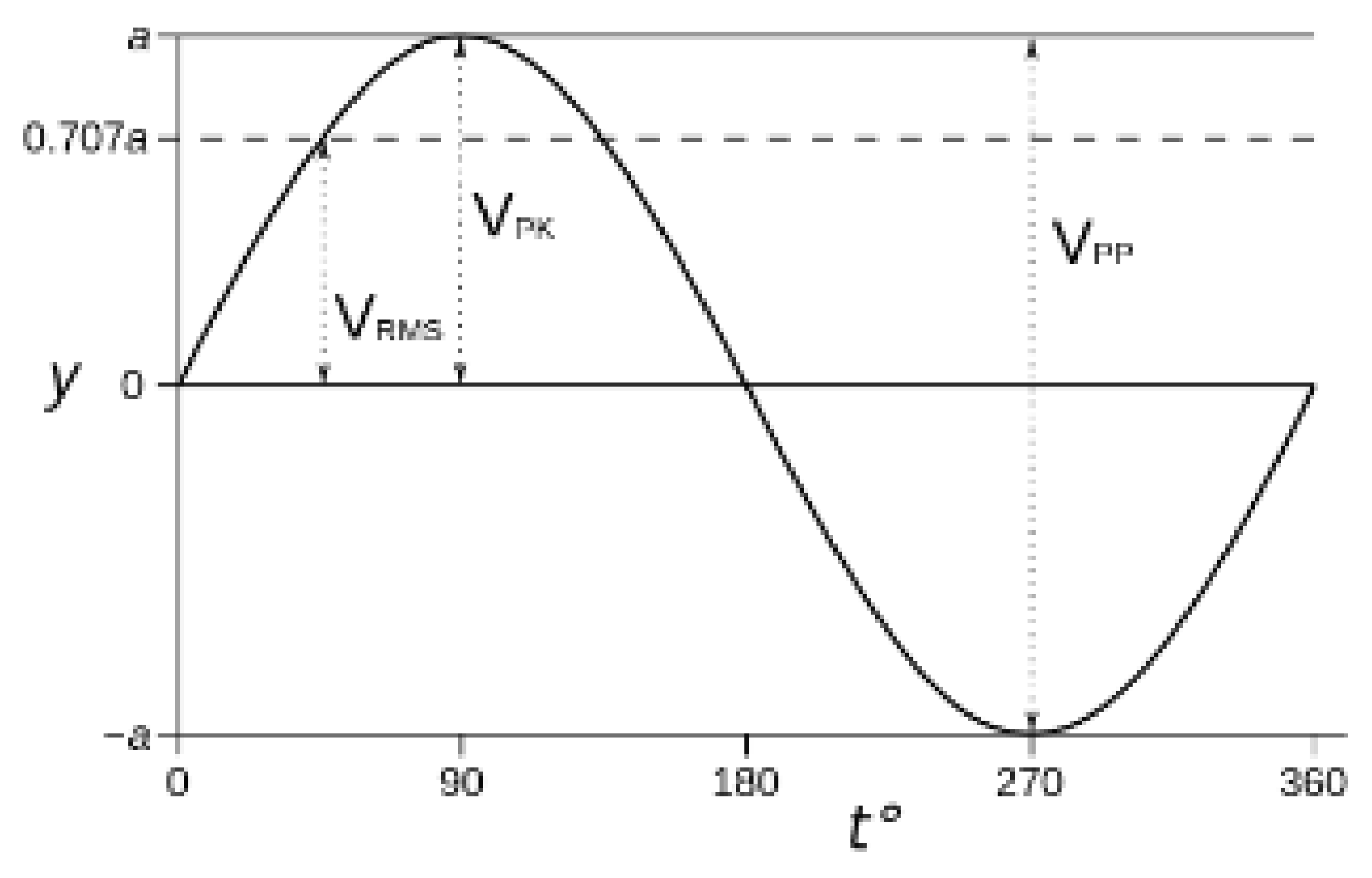 |
1 rms = root-mean-square, p-p = peak-to-peak; p-p = (22–√2 rms) for sinusoidal waves. For EM fields, all p-p values are converted into rms. When * is placed close to the number, it means that it is not specified in the relevant paper if the value is p-p or rms. Since the effective value of an AC field is the rms one, it is reasonable to assume that when not specified, the given value is the rms one. | ||||||
| Facility (Name/Institution and Location) |
Building Construction Details | Laboratory Design | Microscope Name (Year of Installation) (Microscope Info: Maximum Voltage, Electron Optics Peculiarities, Reached Resolution) |
Additional Data on Microscope Performances and Noise Shielding |
|---|---|---|---|---|
| Brookhaven National Laboratory Long Island, NY 11973, USA [1][10] |
Completely renewed 50-year-old building (previously a gym) | no details are given | JEOL JEM2200FS (2004, Jeol Ltd. Akishima, Tokio, Japan) (200 kV Schottky FEG, probe corrected, in column energy filter, 0.12 nm information limit, HAADF STEM resolution 0.105 nm) JEOL JEM2200MCO (2008) (200 kV Schottky FEG, URP objective lens, monochromator, double corrected, in column energy filter, 0.1 nm point and HAADF resolution, energy resolution of the omega filter 1.0–1.1 eV at ~100 µA emission current and 0.7 eV at ~30 µA) |
→ Both microscope columns based on JEM2010F design, with 25 cm diameter column. Not suitable for long corrected column (JEM2010F length 2.5 m against 3.68 m of JEM2200MCO) → Contrast dip between dumbbells in Si [110] zone axis better than 20% (for JEM2200MCO) |
| → New building on a selected 5300-acre site with few sources of vibration and EM interference → Entire building constructed on compacted structural fill, compressed to 98% maximum dry density |
→ Room-in-room concept: Instrument Room (IR), Equipment Room (ER) 15 cm air gap between inner and outer walls. External room with walls and ceiling in aluminum prefabricated modules, internally covered with 10-cm thick polyurethane foam insulation panels. → Control Room (CR) with double-glass panels for viewing the microscope room → Separated 3-m galley for all vibrating equipment (vacuum pumps and water chillers) |
Hitachi HD2700C (2007) (200 kV cold FEG, dedicated STEM, probe corrected, 0.1 nm HAADF resolution, 0.35 eV energy resolution) |
→ Equipped with a telephone-booth-like metal box to reduce acoustic noise and thermal drift → 24 cm column diameter → 56% contrast between Ba and background in HAADF image of BaTiO3 |
|
| Titan 80-300 (2007) (300 kV Schottky FEG, image Cs corrector, environmental TEM, 0.07–0.08 nm information limit, 0.66 eV energy resolution at 300 kV) |
→ 30 cm column diameter specifically designed for mechanical and thermal stability → Contrast dip between dumbbells in Si [211] zone axis of about 20% |
|||
| Max-Planck-Institut für Metallforschung Stuttgart, GERMANY [11] |
Newly designed and constructed room | JEM ARM 1250 (1994) (1250 kV, thermionic LaB6 cathode, 0.105 nm point resolution, 0.085 nm information limit) |
→ High voltage stability: <10−6/min p-p → Objective lens current stability <6 × 10⁻⁷/min p-p → Specimen drift ≤ 0.004 nm/min → ΔE: 0.6–1.6 eV depending on the operation and acquisition conditions |
|
| One-Ångström Microscope Lab (OÅM) Lawrence Berkeley National Laboratory Berkeley, USA [8][9][12][13][14] |
Newly designed and constructed building | → IR and separated ER for all noisy ancillary equipment. Walls between IRs and back rooms up to the base of the second floor to ensure acoustic separation. | Philips CM300UTFEG (2001) (300 kV, Schottky FEG, HREM resolution 0.089 nm, 0.078–0.080 nm information limit, 0.85 eV gun energy spread) |
→ Improved information limit from 0.107 to 0.078 thanks to the high-stability of the power supplies, and hardware corrector for three-fold astigmatism → Sub-Å resolution can be accessed (in the absence of a TEM Cs-corrector) using the focal-series reconstruction (FSR) technique |
| The Triebenberg Laboratory Dresden, GERMANY [8][15] |
Laboratory designed and constructed from the outset on a site selected ad hoc for its peculiarities of isolation and distance from populated areas | → Two buildings, one for media supply, power control and conditioning system, the other for microscopes → Microscope building with six microscope units, each consisting of a microscope room, a room for peripheral devices (power supply, computers, cooling units), and an office → Room-in-room design with the interior walls of the IR 36-cm thick, at 10-cm separation from the external walls, and on a separate foundation |
Philips CM30FEG UT/Special-Tübingen TEM (2000) (200 kV Schottky FEG, point resolution 0.165 nm (5.9 nm−1), information limit 0.091 nm (11 nm−1)) |
The spatial resolution of the CM30FEG improved from 1.2 Å to 0.9 Å when re-sited in the Triebenberg Laboratory |
| Advanced Microscopy Laboratory Oak Ridge National Laboratory Oak Ridge, Tennessee, USA [8][13][16][17] |
→ New specially designed building → Building with “house-in-house” design. External walls with 12-inch concrete blocks and internal room walls with 8-inch concrete blocks → “Slab-on-grade” foundation, with instrument room slabs and wall footings on a previously prepared site comprising several layers of “engineered fill” (to a depth of 8 feet) separated by layers of a “geotechnical fabric” material that together provide a stable, uniform base for the laboratory |
→ IRs separated from CR and sharing an acoustically isolated common chase, for all ancillary equipment, except water chillers → IR floor slabs (1′ thick, and the full area of the room) isolated from the CRs, corridors and service chase Access to CR through a vestibule and an air lock access slot (space) → Isolated mechanical building (200 feet from the microscope suite) for dedicated 75 kVA power supply unit, air handling systems, water chiller units, each supported on separate slabs → Separate control of airflow and temperature for each area |
JEOL JEM 2200FS (2004) (200 kV Schottky FEG, probe Cs corrected, in column energy filter, information limit 0.085 nm, energy spread from 1.3 eV down to 0.7 eV depending on the gun conditions) VG HB-501 (2004) (Dedicated probe Cs corrected STEM) VG HB-603UX (2004) (Dedicated probe Cs corrected STEM, 0.05 nm nominal resolution) |
(Data relevant to JEOL JEM 2200 FS) → Operated solely via remote computer control, no standard viewing chamber with fluorescent screen provided → Measured HT voltage stability of 0.6 × 10⁻⁶ (rms) and OL current stability of 0.25 × 10⁻⁶ (rms) giving a defocus spread of 1.85 nm and an information limit of 0.085 nm → Just after the installation, due to bad environment conditions, scarcely resolved dumbbell spacings of 0.136 nm in Si [110] similar to the same instrument without Cs aberration corrector |
References
- Muller, D.A.; Grazul, J. Optimizing the environment for sub-0.2 nm scanning transmission electron microscopy. J. Electron. Micros. 2001, 50, 219–226.
- Muller, D.A.; Kirkland, E.J.; Thomas, M.G.; Grazul, J.L.; Fitting, L.; Weyland, M. Room design for high-performance electron microscopy. Ultramicroscopy 2006, 106, 1033–1040.
- Muller, D.A.; Grazul, J. Optimizing the environment for sub-0.2 nm scanning transmission electron microscopy. J. Electron. Micros. 2001, 50, 219–226.
- Friedl, K.; Fisslthaler, E.; Grogger, W.; Schmautzer, E. Magnetfeldkompensation in Elektronenmikroskopie-Räumen. Elektrotechnik Informationstechnik 2011, 128, 395–403.
- Rhee, K.-N.; Olesen, B.W.; Kim, K.W. Ten questions about radiant heating and cooling systems. Build. Environ. 2017, 112, 367–381.
- Rhee, K.-N.; Kim, K.W. A 50 year review of basic and applied research in radiant heating and cooling systems for the built environment. Build. Environ. 2015, 91, 166–190.
- O’Keefe, M.A.; Turner, J.H.; Musante, J.A.; Hetherington, C.J.D.; Cullis, A.G.; Carragher, B.; Jenkins, R.; Milgrim, J.; Milligan, R.A.; Potter, C.S.; et al. Laboratory Design for High-Performance Electron Microscopy. Microsc. Today 2004, 12, 8–17.
- O’Keefe, M.A.; Hetherington, C.J.D.; Wang, Y.C.; Nelson, E.C.; Turner, J.H.; Kisielowski, C.; Malm, J.-O.; Mueller, R.; Ringnald, J.; Pan, M.; et al. Sub-Angstrom high-resolution transmission electron microscopy at 300 keV. Ultramicroscopy 2001, 89, 215–241.
- Klie, R.F.; Johnson, C.; Zhu, Y. Atomic-Resolution STEM in the Aberration-Corrected JEOL JEM2200FS. Microsc. Microanal. 2008, 14, 104–111.
- Phillipp, F.; Höschen, R.; Osaki, M.; Möbus, G.; Rühle, M. New high-voltage atomic resolution microscope approaching 1 Å point resolution installed in Stuttgart. Ultramicroscopy 1994, 56, 1–10.
- Turner, J.H.; O’Keefe, M.A.; Mueller, R. Design and Implementation of a Site for a One-Ångstrom TEM. Microsc. Microanal. 1997, 3, 1177–1178.
- O’Keefe, M.A.; Allard, L.F.; Blom, D.A. HRTEM imaging of atoms at sub-Ångström resolution. J. Electron Microsc. 2005, 54, 169–180.
- O’Keefe, M.A. Seeing atoms with aberration-corrected sub-Angstrom electron microscopy. Ultramicroscopy 2008, 108, 196–209.
- Lichte, H.; Schulze, D.; Lehmann, M.; Just, H.; Erabi, T.; Furst, P.; Gobel, J.; Hasenpusch, A.; Dietz, P. The Triebenberg Laboratory-designed for highest resolution electron microscopy and holography. Microsc. Microanal. 2001, 7, 894–895.
- Allard, L.F.; Blom, D.A.; O’Keefe, M.A.; Kiely, C.; Ackland, D.; Watanabe, M.; Kawasaki, M.; Kaneyama, T.; Sawada, H. First Results from the Aberration-Corrected JEOL 2200FS-AC STEM/TEM. Microsc. Microanal. 2004, 10, 110–111.
- Blom, D.A.; Allard, L.F.; Mishina, S.; O’Keefe, M.A. Early Results from an Aberration-Corrected JEOL 2200FS STEM/TEM at Oak Ridge National Laboratory. Microsc. Microanal. 2006, 12, 483–491.

