Submitted Successfully!
To reward your contribution, here is a gift for you: A free trial for our video production service.
Thank you for your contribution! You can also upload a video entry or images related to this topic.
Version Summary Created by Modification Content Size Created at Operation
1 -- 3318 2023-04-28 09:48:25 |
2 Replace clearer figure -14 word(s) 3304 2023-05-03 03:26:43 | |
3 Figure revised. Meta information modification 3304 2023-05-05 11:22:03 |

Video Upload Options

Do you have a full video?

Confirm

Are you sure to Delete?
Cite
If you have any further questions, please contact Encyclopedia Editorial Office.
Zhaksylyk, A.; Rasool, H.; Abramushkina, E.; Chakraborty, S.; Geury, T.; El Baghdadi, M.; Hegazy, O. Active Front-End Rectifiers in EV DC Charging Applications. Encyclopedia. Available online: https://encyclopedia.pub/entry/43611 (accessed on 08 May 2024).
Zhaksylyk A, Rasool H, Abramushkina E, Chakraborty S, Geury T, El Baghdadi M, et al. Active Front-End Rectifiers in EV DC Charging Applications. Encyclopedia. Available at: https://encyclopedia.pub/entry/43611. Accessed May 08, 2024.
Zhaksylyk, Assel, Haaris Rasool, Ekaterina Abramushkina, Sajib Chakraborty, Thomas Geury, Mohamed El Baghdadi, Omar Hegazy. "Active Front-End Rectifiers in EV DC Charging Applications" Encyclopedia, https://encyclopedia.pub/entry/43611 (accessed May 08, 2024).
Zhaksylyk, A., Rasool, H., Abramushkina, E., Chakraborty, S., Geury, T., El Baghdadi, M., & Hegazy, O. (2023, April 28). Active Front-End Rectifiers in EV DC Charging Applications. In Encyclopedia. https://encyclopedia.pub/entry/43611
Zhaksylyk, Assel, et al. "Active Front-End Rectifiers in EV DC Charging Applications." Encyclopedia. Web. 28 April, 2023.
Active Front-End Rectifiers in EV DC Charging Applications
Edit

Active Front-End (AFE) rectifiers have regained momentum as the demand for highpower Electric Vehicle (EV) charging infrastructure increases exponentially. AFE rectifiers have high efficiency and reliability, and they minimize the disturbances that could be generated due to the operation of the EV charging systems by reducing harmonic distortion and operating close to the Unity Power Factor (UPF).

AFE rectifier modular DC charger

1. Introduction

Electric Vehicle (EV) chargers can be classified into three levels based on their power rating, as shown in Table 1. Moreover, they are also categorized as on-board and off-board based on their location. On-board chargers have the convenience of being fairly independent of the charging infrastructure and having the freedom to charge at residential or office spaces where the user would be spending time anyway. On-board chargers can be in charger power Levels 1 or 2 because they have space and weight constraints, so their power rating is limited by the power density of the converter. These chargers cannot deliver the same speed of charging as higher power off-board chargers.

Table 1. EV charger power levels adapted from [1][2][3][4].
EVC Level Voltage Level (US/EU) Grid Supply Location Power Charging Time
Level 1 120/230 VAC 1-phase On-board <3.7 kW 8–16 h
Level 2 240/400 VAC 1- or 3-phase On- or Off-board 3.7–22 kW 2–6 h
Level 3 208–600 VDC 3-phase Off-board 22–350 kW 10–30 min
Ultra-fast charger >800 VDC 3-phase Off-board >400 kW 5–15 min

2. Comparison of Active Front-End (AFE) Topologies

The unidirectional rectifiers only support drawing power from the grid to charge the EV battery. Examples of unidirectional rectifiers include simple diode bridge rectifiers, Vienna rectifiers, Swiss rectifiers, and other well-established topologies. The bidirectional rectifiers can feed power from the vehicle back to the grid when necessary. The V2G operation has been proven beneficial in lower-power chargers, while its use in high-power chargers is relatively new. Level 3 bidirectional AFE rectifiers with V2G capabilities are used in DC fast charging stations with renewable energy sources and energy storage systems to offset the effect of the fast chargers on the grid and to provide additional grid services [5][6]. Within bidirectional rectifiers, there are two types: boost-type and buck-type. The boost-type rectifiers have higher DC link voltage compared to the AC side voltage, while it is the opposite for the buck-type. The higher DC link voltage means less current for the same power level, which can be beneficial, especially for high-power systems.

The topology of the high-power rectifier has to be selected based on several criteria:
  • Three-phase boost-type rectifier topology suitable for Level 3 DC fast charging or ultra-fast charging;
  • Injects minimal THD to the grid;
  • Bidirectionality is advantageous since it enables a V2G operation;
  • Smaller number of components is advantageous for system reliability and cost.

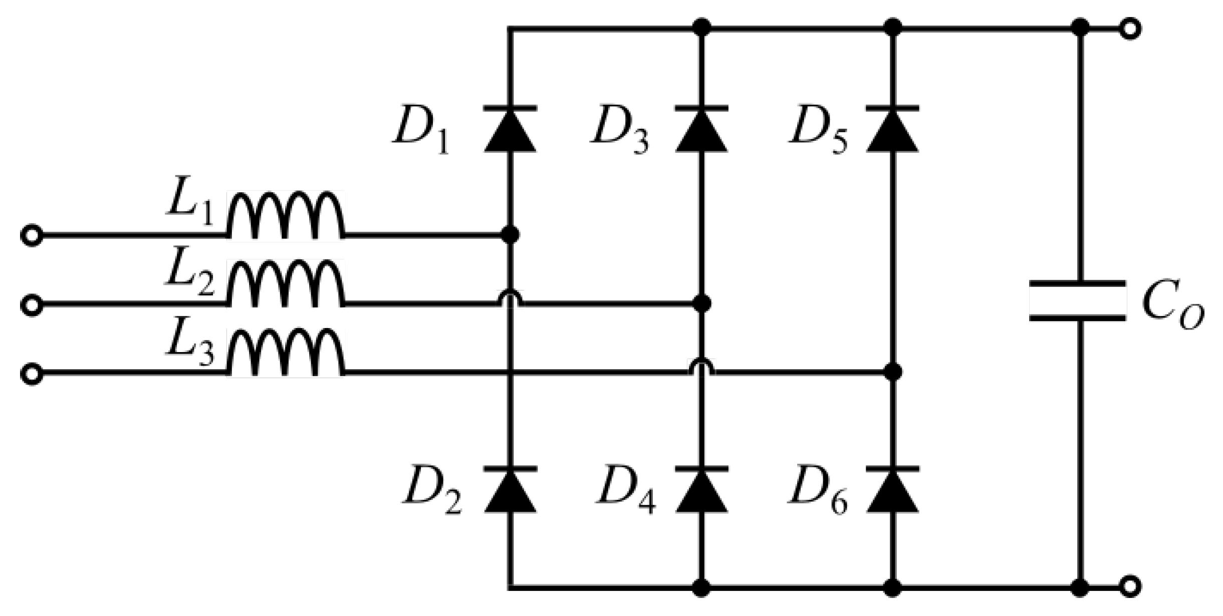
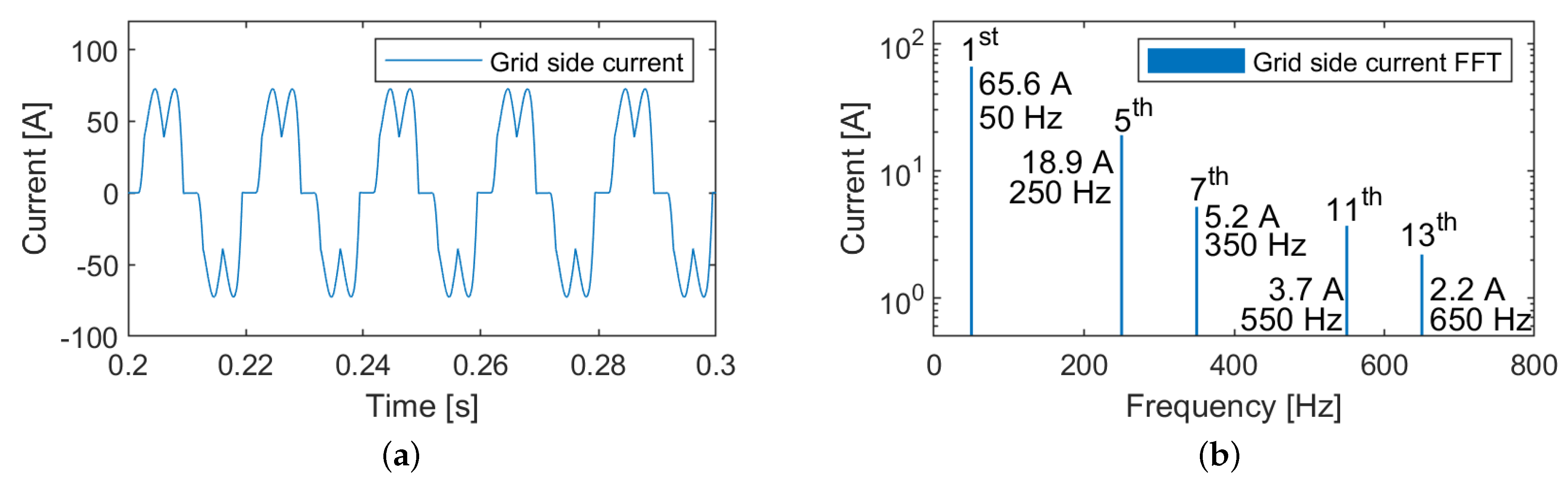
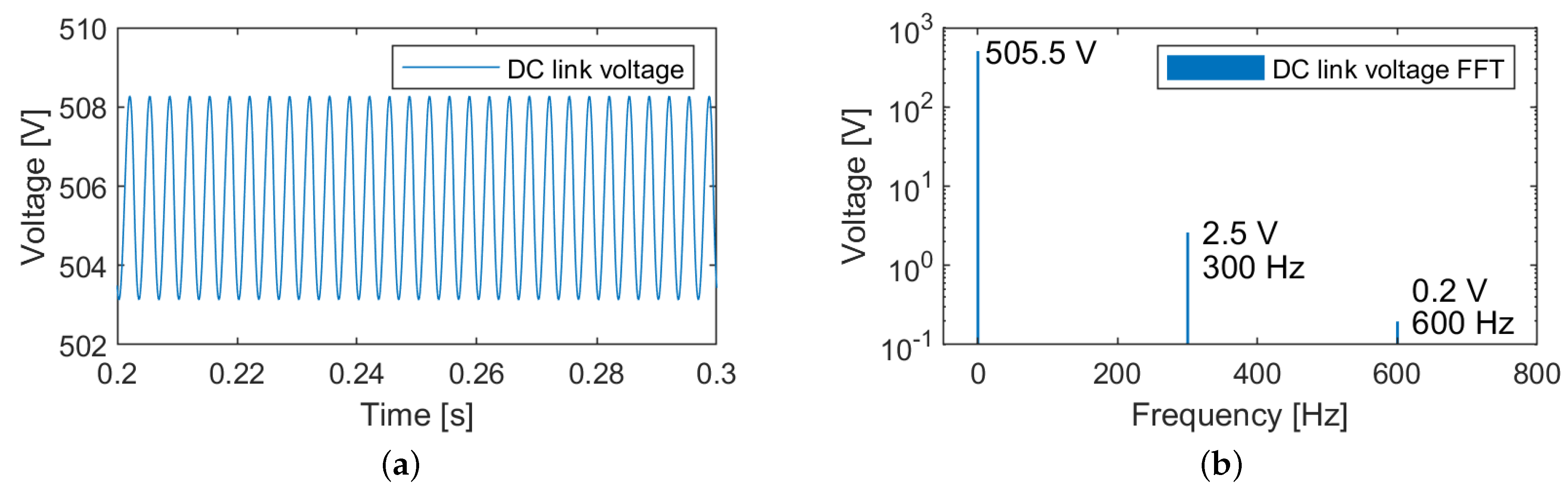
2.1. Three-Phase Passive Rectifier

The three-phase diode rectifier is the simplest rectifier topology. It contains only the six diodes, AC side inductors, and the DC side capacitor, as shown in Figure 1.
Figure 1. Three-phase passive rectifier.
Since it does not employ any active switches, this converter does not require a control system or gate drivers, which simplifies its operation. The diodes switch at grid frequency, and there is no active current shaping and no control over the output voltage. The diode rectifiers can inject a Total Harmonic Distortion (THD) of 40–70% into the grid currents, and large numbers of fast high-power passive rectifiers would cause stress on the grid [7]. This type of conventional passive rectifier topology is not recommended in fast charging applications due to its lower efficiency, unidirectional power flow, and higher THD.
The operation of the passive rectifier has been simulated in a MATLAB (R2021a, MathWorks, Natick, MA, USA) Simulink environment.For this simulation, the DC side capacitive filter is designed for a 1% voltage ripple on the DC link. The AC side smoothing inductor is designed for an impedance ratio of 0.05, the lower end of the acceptable 0.05–0.15 range [8]. Figure 2 shows the grid side current of the passive rectifier and its harmonic analysis. The current is not sinusoidal and has high amplitudes of lower order (5th, 7th, 11th, and 13th) harmonics.
Figure 2. Passive rectifier simulation results. (a) Grid side current. (b) Grid side current harmonic analysis.
Figure 3 shows the DC link voltage of the passive rectifier and its harmonic analysis. The DC link voltage is not controlled and settles around 505.5 V for the given load of 30 kW. The peak-to-peak value of the voltage ripple is 5.14 V, close to 1% of the DC link voltage, which is in line with the design expectations. As shown in Figure 3b, the main voltage ripple harmonic appears at 300 Hz with an amplitude of 2.5 V.
Figure 3. Passive rectifier simulation results. (a) DC link voltage. (b) DC link voltage harmonic analysis.
With the passive rectifier topology, the DC link voltage is not controlled. Moreover, the grid side currents with dominant low-frequency harmonics result in a THD of 30.9% and a power factor of 0.87. In contrast, if active rectifiers are used, the desired voltage level can be maintained with varying loads, and the THD can be kept minimal while achieving high efficiency and power factor. In the following part, the following boost-type bidirectional active converters are compared:
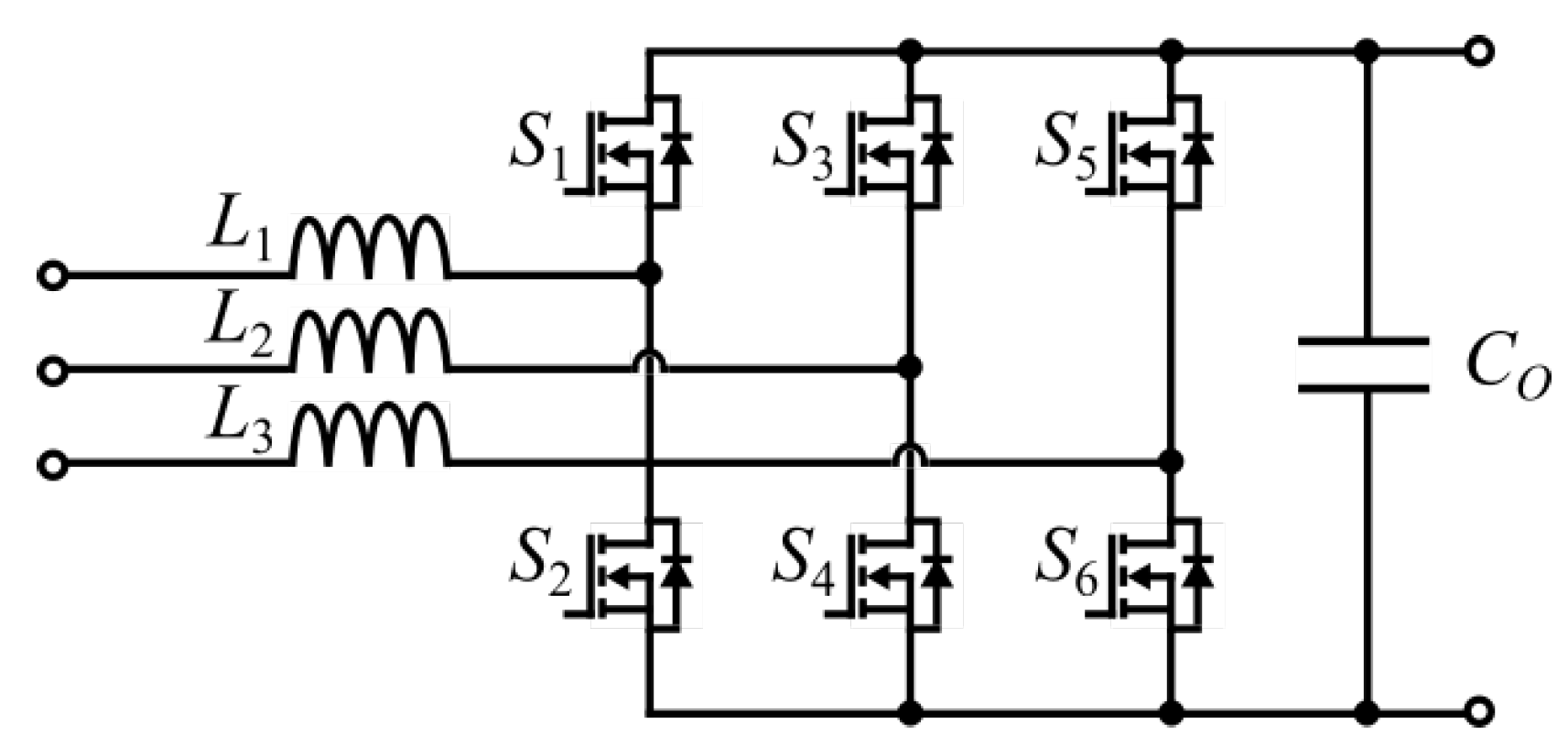
  • Three-phase two-level six-switch boost-type rectifier;
  • Three-phase three-level neutral point clamped converter;
  • Three-phase three-level T-type converter.
To compare the AFE topologies, they have been designed for similar conditions and simulated. The active rectifiers are designed for 1% ripple on the DC link and 5% THD of grid currents at full load. All three active converters switch at 20 kHz and are rated for 30 kW. The DC link voltage setpoint is 700 V.

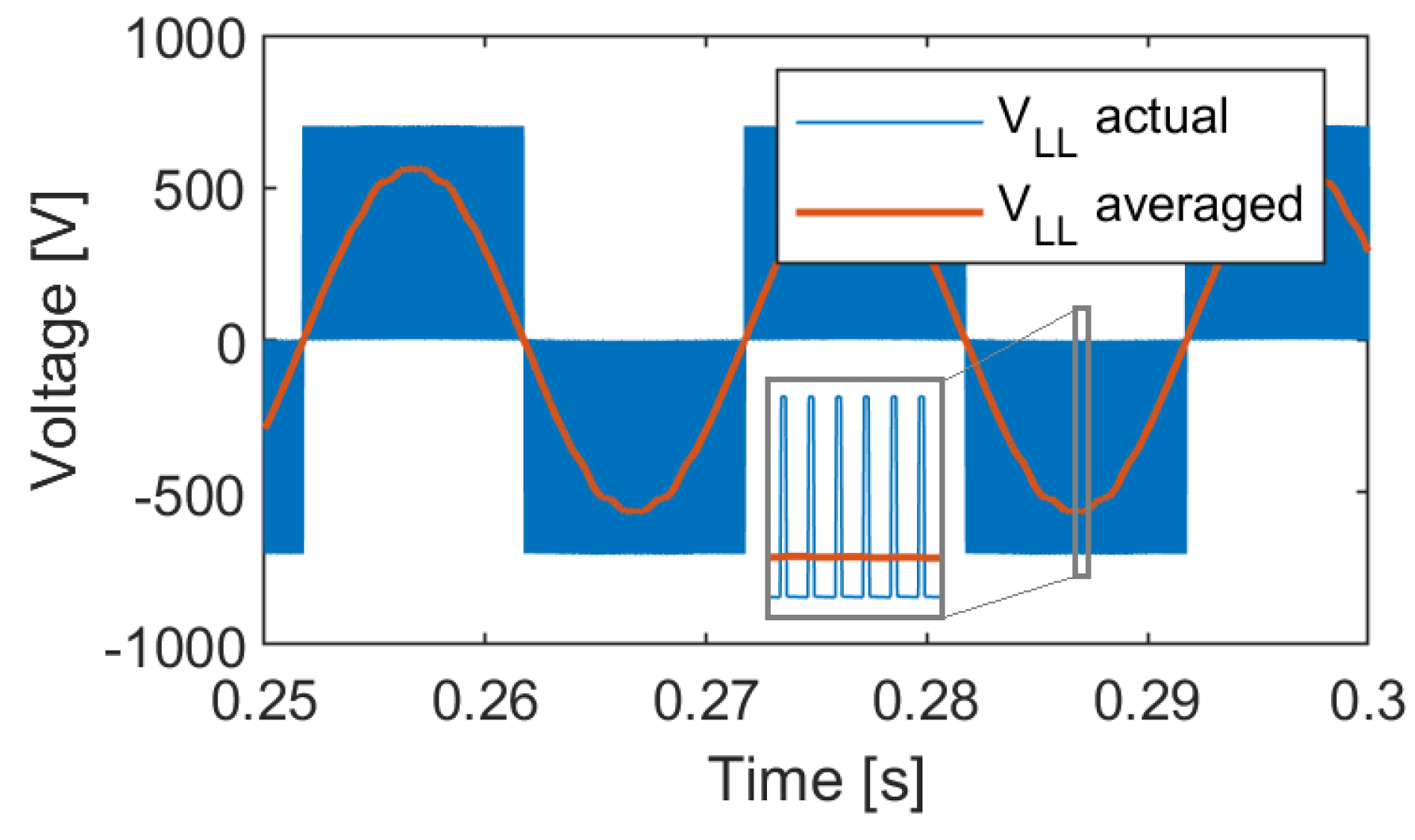
2.2. Three-Phase Two-Level Six-Switch Boost-Type Rectifier

The topology for the three-phase two-level boost-type rectifier is shown in Figure 4. It consists of six active switches, AC side boost inductors, and a DC side filter capacitor. The topology of the boost-type two-level rectifier is simple, robust, and well-known. This topology can be built using commercial H-bridges. The two-level six-switch rectifier topology requires larger volume input inductors and has a limited maximum switching frequency [9] compared to the three-level converters. The lower boundary of the DC link voltage has to be limited due to the boosting nature of the rectifier. For example, if the rectifier is connected to the three-phase grid with 400 V RMS line-to-line voltage, then the minimum DC link voltage will be 565 V, equal to the line-to-line voltage amplitude. Ideally, it should be at least 15–20% higher to reduce the distortion in current waveforms.
Figure 4. Three-phase two-level six-switch boost-type rectifier.
In a two-level topology line-to-neutral rectifier, the voltage is either zero or equal to the DC link voltage. This creates a three-level line-to-line voltage, as shown in Figure 5.
Figure 5. Two-level six-switch boost-type rectifier simulation results: line-to-line voltage.

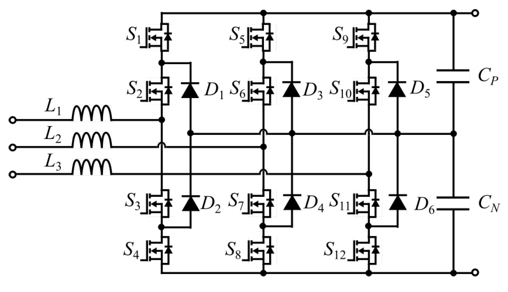
2.3. Three-Phase Three-Level Neutral Point Clamped Converter

The topology of a three-phase three-level neutral point clamped (NPC) converter is shown in Figure 6. It is a three-level topology consisting of twelve active switches, six diodes, and filters. Compared to the two-level converter, switches in this topology see reduced voltage stress and lower switching losses. Moreover, the passive filter size is smaller. However, the component count increases, negatively affecting system reliability, complexity, and implementation effort.
Figure 6. Three-phase three-level neutral point clamped converter.
The NPC converter follows the DC link voltage setpoint. The DC link voltage ripple is 1%, and the grid side current THD is 5% at full load as designed. The power factor is 0.997, and the efficiency of the converter is 98.2% at full load. The main drawback of the NPC topology is that it uses 12 active and 6 passive switches, which makes it costly and complex. However, it significantly reduces the inductor size (44% reduction in this case), and the switches are all subjected to only half the DC link voltage. This topology requires two capacitors in series, which leads to higher capacitance values and lower capacitor voltage ratings.

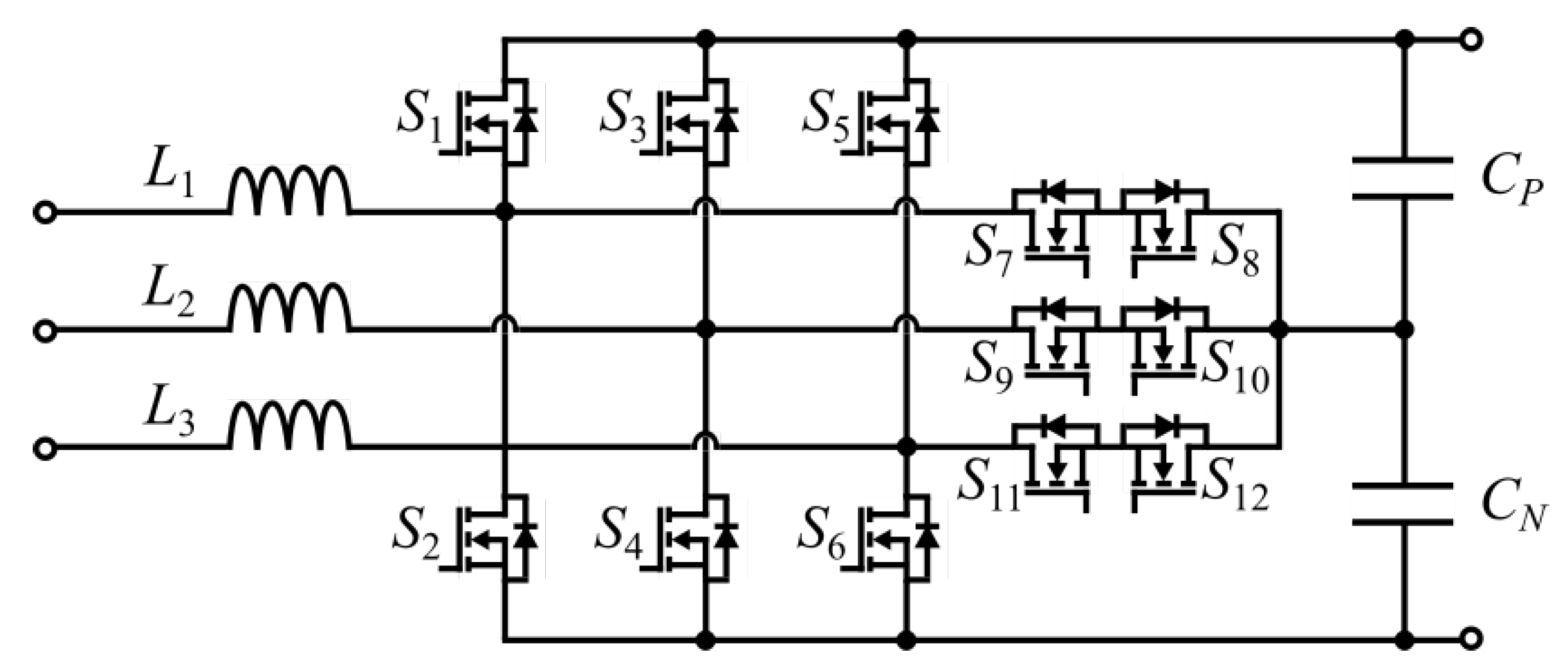
2.4. Three-Phase Three-Level T-Type Converter

Three-phase three-level T-type converter is a bidirectional variation of the three-phase Vienna rectifier. The topology is shown in Figure 7 [9][10]. This rectifier uses 12 active switches, compared to the original unidirectional topology that uses 6 diodes and 6 active switches [8]. Moreover, it has three boost inductors on the AC side and a split capacitor on the DC side. This is a three-level topology similar to NPC. However, it has lower semiconductor losses for low switching frequencies compared to NPC, and it can be implemented using standard six-pack modules. This topology uses switches for two different voltage ratings.
Figure 7. Three-phase three-level T-type converter.

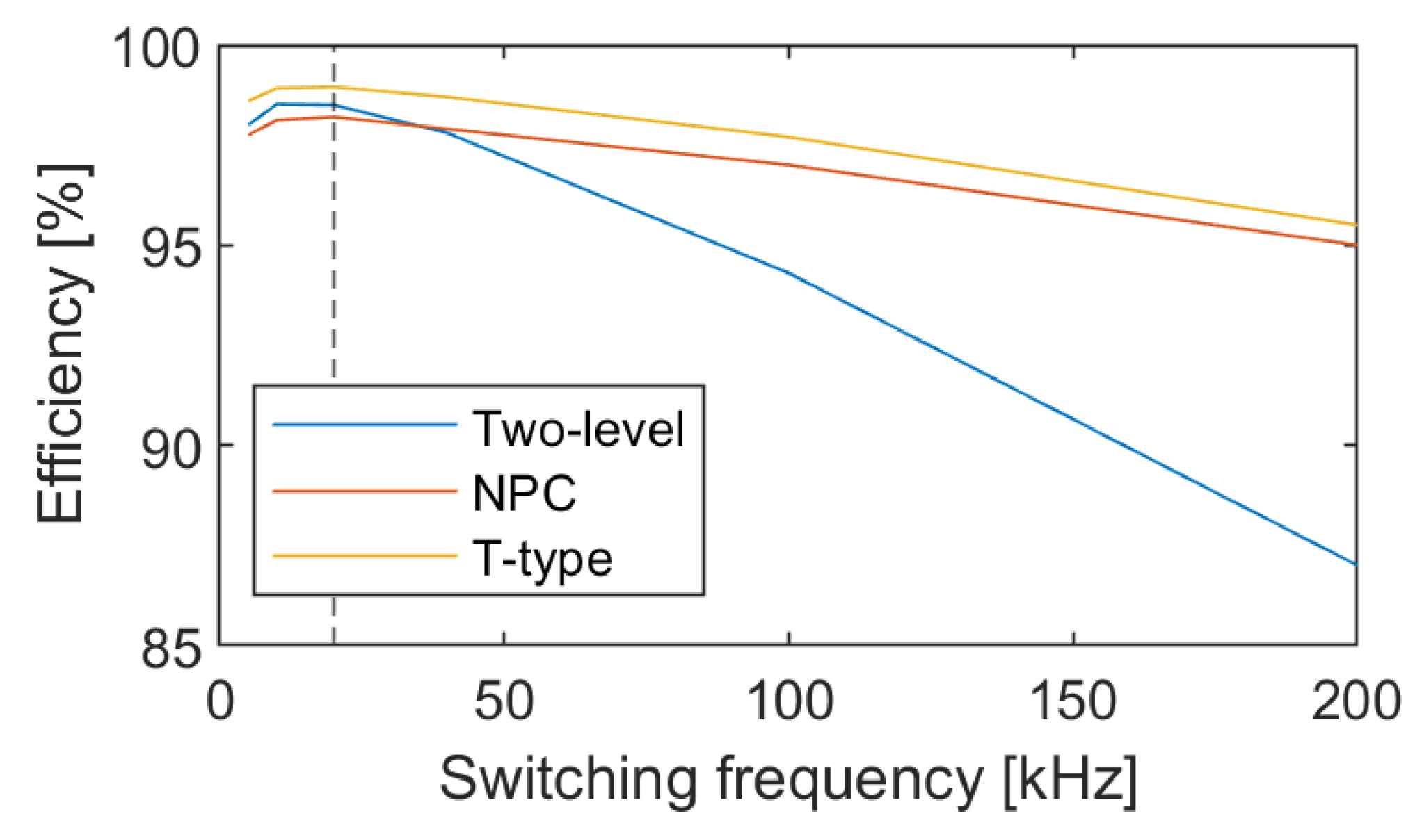
2.5. Comparison of Rectifier Topologies

A comparison of different AFE topologies and the passive rectifier performances at full load is presented in Table 2. To perform a quantitative comparison of the rectifier topologies, they have been simulated in MATLAB Simulink. Each rectifier is designed for 30 kW using SiC devices. The output voltage of the passive rectifier cannot be controlled. Therefore, it differs from the active rectifier output voltage, which is 700 V. The active rectifiers switch at 20 kHz. The filters are designed for 1% voltage ripple at the DC link and 5% THD of the grid side currents at full load. The required AC side inductance is twice smaller for three-level topologies for the same level of current ripple. The DC link capacitance is higher for three-level topologies due to the series connection. However, the voltage rating for the capacitor is lower for NPC and T-Type. The switches on the three-level topologies are subjected to less stress, which increases the lifetime of individual switches. However, the higher component number in three-level topologies negatively affects the overall converter reliability. The control of the three-level topologies can be as simple as two-level topologies, with modifications to the modulation scheme. However, three-level topologies may require balancing between the series capacitances, which can complicate the control system. The higher number of components increases the cost of three-level topologies compared to the two-level.
Table 2. Comparison of rectifier topologies.
  Passive Rectifier Six-Switch Rectifier NPC Rectifier T-Type Rectifier
Bidirectional No Yes Yes Yes
Output DC voltage 505.5 V 700 V 700 V 700 V
Output DC current 59.3 A 42.8 A 42.8 A 42.8 A
Efficiency 91% 98.5% 98.2% 98.95%
Grid current THD 30.9% 5% 5% 5%
Power Factor 0.87 0.997 0.997 0.997
Number of active switches 0 6 12 12
Number of passive switches 6 0 6 0
Switch blocking voltage stress VDC��� VDC��� 0.5 VDC��� VDC��� (6), 0.5 VDC��� (6)
DC link capacitance for 1% VDC��� ripple 3000 μF 87 μF 2 × 350 μF 2 × 350 μF
DC link capacitor voltage rating VDC��� VDC��� 0.5 VDC��� 0.5 VDC���
AC side inductance for 5% THD 0.96 mH 0.44 mH 0.238 mH 0.238 mH
Cost Low Average High High
Reliability High Higher stress on individual components, Lower component count Lower stress on individual components, higher component count Lower stress on individual components, higher component count
At 20 kHz switching frequency, the T-type rectifier shows the highest efficiency (98.95%), with a two-level rectifier in second place (98.5%) and NPC in third place (98.2%). This is in line with the behavior reported in [11]. At the lowest switching frequency, the efficiency from high to low is T-type, two-level, and then NPC. For insulated-gate bipolar transistor (IGBT) modules used in [11], that behavior continues until approximately 8 kHz. When the switching frequency increases, the efficiency of the two-level rectifier decreases much more rapidly compared to three-level topologies. The efficiency of NPC decreases the least with the increase in frequency. Therefore, after a certain high frequency (36 kHz for IGBT modules in [11]), NPC will be the most efficient topology. Using Silicon Carbide (SiC) devices, this behavior does not appear until 200 kHz, as shown in Figure 8.
Figure 8. Simulated efficiency of AFE topologies for various switching frequencies.

3. Components of AFE Rectifiers

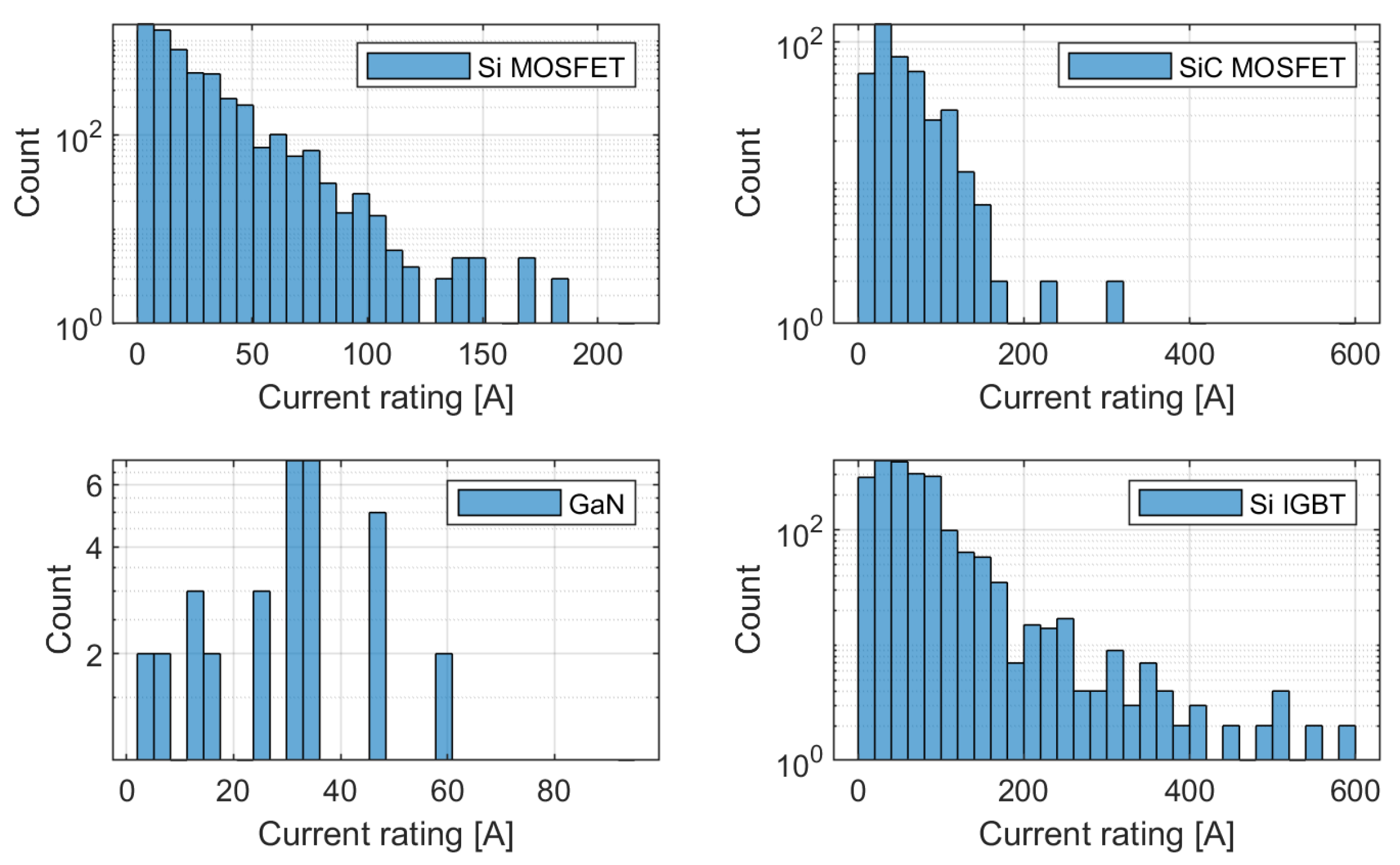
3.1. Power Semiconductor Selection

Switches comprise the main part of the AFE rectifier. The efficiency and reliability of these switching components are crucial for the performance of the entire AFE system [4]. With the emergence of new and improved devices, such as Wide Band-Gap (WBG) semiconductor switches, the AFE rectifier performance can be improved substantially [12][13][14]. The WBG devices can withstand higher junction temperatures, block higher voltages, and operate under higher switching frequencies. Moreover, switching and conduction losses are lower in WBG devices [15]. WBG active switches allow higher power density in the weight and volume constraints of the on-board charger while allowing off-board chargers to operate at even higher power levels. The efficiency of WBG chargers is reaching as high as 98.5% [16][17].

3.2. DC Link Capacitor Selection

DC link capacitors are one of the main components of power electronic converters. There are three main types of capacitors used in automotive applications: Aluminum Electrolytic Capacitors, Metallized Polypropylene Film (MPPF) Capacitors, and high-capacitance Multi-Layer Ceramic (MLC) Capacitors [18]. Electrolytic capacitors are more cost-effective and have the highest energy density and capacitance. Typically, the required capacitance values for AFE DC link capacitors in fast charging applications are not high, especially if compared to the capacitors in single-phase chargers. However, the current rating of these capacitors has to keep up with the high-power rating of the fast chargers. MLC capacitors have better reliability and can perform under higher temperatures and frequencies [18]. Operating at higher switching frequencies allows the use of smaller filter components and minimizes the grid disturbance of the fast charger. Since fast charger components are expected to perform in very harsh conditions, increased reliability is very important. The MPPF capacitors have moderate performance and cost. However, they are limited by their reliability and operating temperature [18].

3.3. Grid Side Filters Selection

The switching converters introduce harmonic currents into the grid. IEEE 519-2014 sets the limits on voltage and current harmonics at the point of common coupling (PCC) [19]. The IEEE 519-2014 states the limit on the individual current harmonics and the total demand distortion (TDD). TDD is the ratio of the root mean square (RMS) of the harmonic content to the maximum demand current. It is important to differentiate between the current THD (THDi) and TDD. THDi uses instantaneous fundamental current as a base, not the maximum demand current. These TDD and THDi values will be equal only when the load is 100%.
In AFE rectifiers, there is a filter on each phase of the converter at the grid side. There are three common types of filter topologies used for the grid-connected VSC: L, LC, and LCL [20]. However, higher-order filters, such as LLCL and LCL-LC, are used too [21]. There is a trade-off between the attenuation level, filter complexity, cost, and control system complexity when considering the topology of the filter. Moreover, with the increased number of components in the filter, the power losses on those components might increase.

4. Control of a Single AFE

There are a number of well-established and widely used control strategies for AFE rectifiers. Figure 9 summarizes the existing control techniques [22][23][24]. Some of the well-established and widely used control strategies for AFE rectifiers are highlighted in blue in Figure 9:
Figure 9. Classification of control systems for AFE rectifiers in EV charging application.
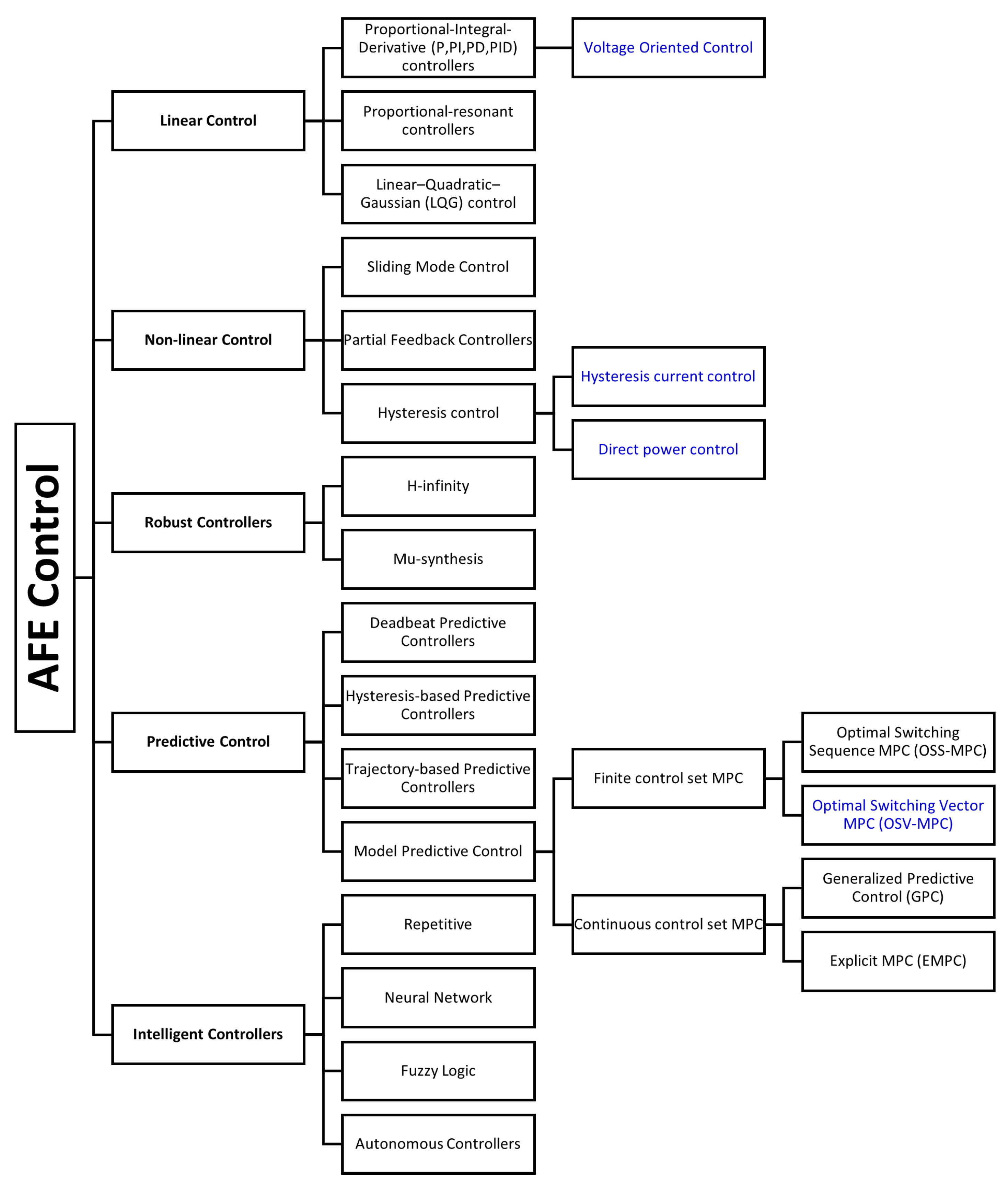
  • Voltage Oriented Control (VOC) is a type of Linear Control with PI controllers.
  • Direct Power Control (DPC) is classified under Non-linear Hysteresis Control since active and reactive power is controlled using a hysteresis controller with a lookup table.
  • Optimal switching vector Model Predictive Control (MPC) is classified under Predictive Control.
  • Hysteresis Current Control (HCC) is a type of Non-linear Hysteresis Control applied directly to phase currents.
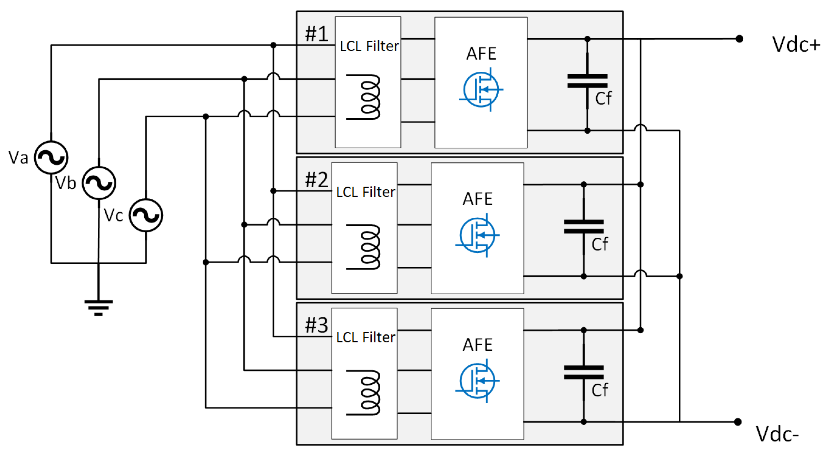
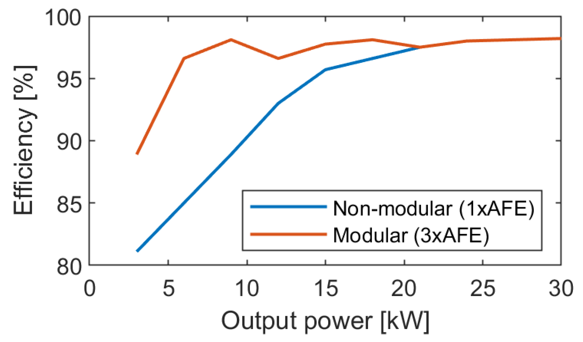
Some of these control techniques are better suited for maintaining the DC bus voltage, while others allow decoupled control of active and reactive power flow. They also vary in the number and types of required sensors, and the complexity of calculations.

5. Modular AFE

With the increasing tendency for high-power chargers in the megawatt range for ultra-fast charging, the standard solution of using a simple single converter is not feasible. Figure 10 shows the distribution of available discrete semiconductors by current rating for applications above 400 V based on the data of over 20,000 devices from Digi-Key Electronics. Please note that the y-axis is a logarithmic scale, so the actual difference between component availability at different current ratings is even more drastic. The majority of Si MOSFETs (99.08%) are available under 100 A and 650 V. While SiC MOSFETs can go much higher in terms of both current and voltage ratings, 87% of SiC MOSFETs are also under 100 A. The majority of available GaN components are rated below 400 V; therefore, the choice of GaN components is very limited. The Si IGBTs have the highest current ratings among all. However, they have much longer switching times compared to the MOSFETs, which means they cannot operate at higher switching frequencies and would result in much bigger filter component sizes. The clear tendency shown in Figure 10 is that with increasing power rating, the number of available components decreases. Building a fast charger AFE would require specialty components with low availability and high cost. The modular approach can be used to solve the issues of component availability in addition to improving system reliability, performance, grid impact, and thermal management.
Figure 10. Distribution of power semiconductors (>400 V) by current rating.
The concept of modularity means that the system is divided into smaller parts, “modules” that can be individually designed, modified, and replaced by other “modules”. Moreover, modules can be exchanged with other systems. When applied to the AFE system, one whole AFE rectifier can be considered a module, and several modules can be joined into one system to build a parallel converter setup, as shown in Figure 11.
Figure 11. Modular AFE system consisting of parallel AFE converters.
A modular approach using parallel converters is advantageous in several ways. One, it allows building high-power systems without the need to use high-power rated components that are costly and not easily available. Moreover, using the same set of modules, different power-rated systems can be built. Using this approach, one can increase or decrease system power rating during operation to optimize efficiency [25]. Failed modules can be isolated to allow the rest of the system to continue operation [26]. Extra modules can be used as a backup to increase system reliability. Therefore, using parallel AFE can be beneficial for system efficiency, reliability, and versatility [27]. Using a modular approach decreases stress on individual components, which results in higher reliability [28]. Figure 12 demonstrates how the efficiency of a 30 kW rectifier system can be improved by using a three-module system instead of a non-modular system.
Figure 12. Simulated efficiency of modular vs. non-modular two-level AFE rectifier.
Moreover, a parallel configuration of AFE allows PWM carrier signal interleaving, which decreases grid current THD [29]. In the case components of sufficient power rating are available, the modular approach is almost always costlier due to the higher number of components, even though part of the cost can be offset with increased efficiency and reliability. Moreover, using parallel AFE configuration can result in circulating currents and increased complexity of the control system [30][31].

6. Cooling System

The cooling technique is crucial for AFE rectifiers as it can affect the system efficiency and lifetime. Moreover, cooling systems are one of the roadblocks in the development of ultra-fast chargers. There are several types of cooling systems commonly used for power electronic converters: forced air cooling, liquid cooling, and other more complex cooling methods [15]. Depending on the type of charger, i.e., on-board or off-board, the cooling system for AFE rectifiers will have different requirements. The main parameters are: the space and weight limitations, power level, and allowed temperature range. If the best-case system efficiency of 97% is assumed, the dissipated power levels for Level 3 chargers will range from 660 W for a 22 kW system up to 10.5 kW for a 350 kW system. Whereas for ultra-fast chargers of above 400 kW power rating, the dissipated power will be more than 12 kW.
Air cooling is relatively simple and cost-effective [15]. It also uses fewer components compared to liquid cooling, which may have a positive effect on the power density of the system [32]. Air cooling can be either non-forced or forced air cooling; forced air cooling can remove more heat from the system.
Liquid cooling has higher heat transfer efficiency [33]. Moreover, liquid-cooled systems have a high ingress protection class [34]. The type of liquid used in this cooling method and the exact construction can vary from case to case. According to [34], liquid cooling systems have a risk of liquid leakage, the equipment is complex, and the cost is high. A combination of a modular approach and liquid cooling can be a suitable solution for high-power fast chargers. An AFE drive with 200 kW modules presented in [35] is able to achieve a 97% efficiency using a liquid cooling system with water. 

References

  1. Yilmaz, M.; Krein, P.T. Review of Battery Charger Topologies, Charging Power Levels, and Infrastructure for Plug-In Electric and Hybrid Vehicles. IEEE Trans. Power Electron. 2013, 28, 2151–2169.
  2. Zamani, M.; Nagrial, M.; Rizk, J.; Hellany, A. Electric Vehicles Charging: Review of Current Status. In Proceedings of the 2018 Australasian Universities Power Engineering Conference (AUPEC), IEEE, Auckland, New Zealand, 27–30 November 2018; pp. 1–5.
  3. Jaman, S.; Chakraborty, S.; Tran, D.D.; Geury, T.; El Baghdadi, M.; Hegazy, O. Review on Integrated On-Board Charger-Traction Systems: V2G Topologies, Control Approaches, Standards and Power Density State-of-the-Art for Electric Vehicle. Energies 2022, 15, 5376.
  4. Rasool, H.; Verbrugge, B.; Zhaksylyk, A.; Tran, T.M.; Baghdadi, M.E.; Geury, T.; Hegazy, O. Design Optimization and Electro-Thermal Modeling of an Off-Board Charging System for Electric Bus Applications. IEEE Access 2021, 9, 84501–84519.
  5. Zabetian-Hosseini, A.; Joos, G.; Boulet, B. Distributed Control Design for V2G in DC Fast Charging Stations. In Proceedings of the 2021 IEEE Energy Conversion Congress and Exposition (ECCE), IEEE, Vancouver, BC, Canada, 10–14 October 2021; pp. 655–661.
  6. Chandler, S.; Gartner, J.; Jones, D. Integrating Electric Vehicles with Energy Storage and Grids: New Technology and Specific Capabilities Spur Numerous Applications. IEEE Electrif. Mag. 2018, 6, 38–43.
  7. Krasselt, P.; Boßle, J.; Suriyah, M.; Leibfried, T. DC-Electric Vehicle Supply Equipment Operation Strategies for Enhanced Utility Grid Voltage Stability. World Electr. Veh. J. 2015, 7, 530–539.
  8. Kolar, J.W.; Friedli, T. The Essence of Three-Phase PFC Rectifier Systems—Part I. IEEE Trans. Power Electron. 2013, 28, 176–198.
  9. Friedli, T.; Hartmann, M.; Kolar, J.W. The Essence of Three-Phase PFC Rectifier Systems—Part II. IEEE Trans. Power Electron. 2014, 29, 543–560.
  10. Halbig, J. 15 kW Bidirectional Vienna PFC. In Proceedings of the APEC2020, New Orleans, LA, USA, 15–19 March 2020.
  11. Schweizer, M.; Kolar, J.W. Design and Implementation of a Highly Efficient Three-Level T-Type Converter for Low-Voltage Applications. IEEE Trans. Power Electron. 2013, 28, 899–907.
  12. Su, G.J. Comparison of Si, SiC, and GaN based Isolation Converters for Onboard Charger Applications. In Proceedings of the 2018 IEEE Energy Conversion Congress and Exposition (ECCE), IEEE, Portland, OR, USA, 23–27 September 2018; pp. 1233–1239.
  13. Gu, X.; Shui, Q.; Myles, C.; Gundersen, M. Comparison of Si, GaAs, SiC and GaN FET-type switches for pulsed power applications. In Proceedings of the Digest of Technical Papers, PPC-2003, 14th IEEE International Pulsed Power Conference (IEEE Cat. No.03CH37472), IEEE, Dallas, TX, USA, 15–18 June 2003; pp. 362–365.
  14. Liu, G.; Bai, K.H.; McAmmond, M.; Brown, A.; Johnson, P.M.; Taylor, A.; Lu, J. Comparison of SiC MOSFETs and GaN HEMTs based high-efficiency high-power-density 7.2 kWEV battery chargers. In Proceedings of the 2017 IEEE 5th Workshop on Wide Bandgap Power Devices and Applications (WiPDA), IEEE, Albuquerque, NM, USA, 30 October–1 November 2017; pp. 391–397.
  15. Abramushkina, E.; Zhaksylyk, A.; Geury, T.; El Baghdadi, M.; Hegazy, O. A Thorough Review of Cooling Concepts and Thermal Management Techniques for Automotive WBG Inverters: Topology, Technology and Integration Level. Energies 2021, 14, 4981.
  16. Zhang, D.; Guacci, M.; Haider, M.; Bortis, D.; Kolar, J.W.; Everts, J. Three-Phase Bidirectional Buck-Boost Current DC-Link EV Battery Charger Featuring a Wide Output Voltage Range of 200 to 1000 V. In Proceedings of the 2020 IEEE Energy Conversion Congress and Exposition (ECCE), IEEE, Detroit, MI, USA, 11–15 October 2020; pp. 4555–4562.
  17. Liu, Z.; Li, B.; Lee, F.C.; Li, Q. High-Efficiency High-Density Critical Mode Rectifier/Inverter for WBG-Device-Based On-Board Charger. IEEE Trans. Ind. Electron. 2017, 64, 9114–9123.
  18. Wang, H.; Blaabjerg, F. Reliability of Capacitors for DC-Link Applications in Power Electronic Converters—An Overview. IEEE Trans. Ind. Appl. 2014, 50, 3569–3578.
  19. Das, J. Harmonic Distortion Limits According to Standards. In Power System Harmonics and Passive Filter Designs; John Wiley & Sons, Inc: Hoboken, NJ, USA, 2015; pp. 427–451.
  20. Yagnik, U.P.; Solanki, M.D. Comparison of L, LC & LCL filter for grid connected converter. In Proceedings of the 2017 International Conference on Trends in Electronics and Informatics (ICEI), IEEE, Tirunelveli, India, 11–12 May 2017; pp. 455–458.
  21. Qian, H.; Xu, J.; Hu, Y.; Xie, S. Design and Comparison of High-Order Output Filters for Grid-Connected Converters with Low Switching Frequency. In Proceedings of the 2021 IEEE 16th Conference on Industrial Electronics and Applications (ICIEA), IEEE, Chengdu, China, 1–4 August 2021; pp. 894–899.
  22. Safayatullah, M.; Elrais, M.T.; Ghosh, S.; Rezaii, R.; Batarseh, I. A Comprehensive Review of Power Converter Topologies and Control Methods for Electric Vehicle Fast Charging Applications. IEEE Access 2022, 10, 40753–40793.
  23. Athari, H.; Niroomand, M.; Ataei, M. Review and Classification of Control Systems in Grid-tied Inverters. Renew. Sustain. Energy Rev. 2017, 72, 1167–1176.
  24. Kazmierkowski, M.; Malesani, L. Current control techniques for three-phase voltage-source PWM converters: A survey. IEEE Trans. Ind. Electron. 1998, 45, 691–703.
  25. Gray, M.; Gao, Z.; Button, R. Distributed, Master-less Control of Modular DC-DC Converters. In Proceedings of the 2nd International Energy Conversion Engineering Conference, Rhodes, Greece, 16–19 August 2004; American Institute of Aeronautics and Astronautics: Reston, VA, USA, 2004.
  26. Zhaksylyk, A.; Rasool, H.; Geury, T.; El Baghdadi, M.; Hegazy, O. Masterless Control of Parallel Modular Active front-end (AFE) Systems for Vehicles and Stationary Applications. In Proceedings of the 2020 Fifteenth International Conference on Ecological Vehicles and Renewable Energies (EVER), IEEE, Monte-Carlo, Monaco, 10–12 September 2020.
  27. Salgado-Herrera, N.; Anaya-Lara, O.; Campos-Gaona, D.; Medina-Rios, A.; Tapia-Sanchez, R.; Rodriguez-Rodriguez, J. Active Front-End converter applied for the THD reduction in power systems. In Proceedings of the 2018 IEEE Power & Energy Society General Meeting (PESGM), IEEE, Portland, OR, USA, 5–10 August 2018.
  28. Zhaksylyk, A.; Hasan, M.M.; Chakraborty, S.; Geury, T.; Hegazy, O. Effects of modularity on the performance and reliability of SiC MOSFET-based active front-end rectifiers in EV charging application. In Proceedings of the IECON 2022—48th Annual Conference of the IEEE Industrial Electronics Society, IEEE, Brussels, Belgium, 17–20 October 2022; pp. 1–7.
  29. Xing, K.; Lee, F.; Borojevic, D.; Ye, Z.; Mazumder, S. Interleaved PWM with discontinuous space-vector modulation. IEEE Trans. Power Electron. 1999, 14.
  30. Lyu, J.; Zhang, J.; Cai, X.; Wang, H.; Dai, J. Circulating current control strategy for parallel full-scale wind power converters. IET Power Electron. 2016, 9, 639–647.
  31. Wang, J.; Hu, F.; Jiang, W.; Wang, W.; Gao, Y. Investigation of Zero Sequence Circulating Current Suppression for Parallel Three-Phase Grid-Connected Converters Without Communication. IEEE Trans. Ind. Electron. 2018, 65, 7620–7629.
  32. Zeng, Z.; Zhang, X.; Blaabjerg, F.; Chen, H.; Sun, T. Stepwise Design Methodology and Heterogeneous Integration Routine of Air-Cooled SiC Inverter for Electric Vehicle. IEEE Trans. Power Electron. 2020, 35, 3973–3988.
  33. Bolte, S.; Henkenius, C.; Bocker, J.; Zibart, A.; Kenig, E.; Figge, H. Water-cooled on-board charger with optimized cooling channel. In Proceedings of the 2017 19th European Conference on Power Electronics and Applications (EPE’17 ECCE Europe), IEEE, Warsaw, Poland, 11–14 September 2017; pp. P.1–P.9.
  34. Fang, X.; Li, J.; Zhang, X.; Chen, W.; Wang, W. Study on Temperature Control Design and High Protection of Charger. In Proceedings of the 2018 10th International Conference on Intelligent Human-Machine Systems and Cybernetics (IHMSC), IEEE, Hangzhou, China, 25–26 August 2018; pp. 216–219.
  35. New Slim Liquid Cooled Active Front End Drive Technology Increases Power Density by 100%; Technical Report; Emotron: Helsingborg, Sweden, 2022.
More
Information
Contributors MDPI registered users' name will be linked to their SciProfiles pages. To register with us, please refer to https://encyclopedia.pub/register : , , , , , ,
View Times: 1.8K
Revisions: 3 times (View History)
Update Date: 05 May 2023
1000/1000