Submitted Successfully!
To reward your contribution, here is a gift for you: A free trial for our video production service.
Thank you for your contribution! You can also upload a video entry or images related to this topic.
Version Summary Created by Modification Content Size Created at Operation
1 -- 5209 2023-04-18 22:06:19 |
2 update references and layout Meta information modification 5209 2023-04-19 03:55:11 |

Video Upload Options

Do you have a full video?

Confirm

Are you sure to Delete?
Cite
If you have any further questions, please contact Encyclopedia Editorial Office.
Costa, R.D.F.S.; Sales-Contini, R.C.M.; Silva, F.J.G.; Sebbe, N.; Jesus, A.M.P. Fiber Metal Laminates. Encyclopedia. Available online: https://encyclopedia.pub/entry/43213 (accessed on 29 August 2024).
Costa RDFS, Sales-Contini RCM, Silva FJG, Sebbe N, Jesus AMP. Fiber Metal Laminates. Encyclopedia. Available at: https://encyclopedia.pub/entry/43213. Accessed August 29, 2024.
Costa, Rúben D. F. S., Rita C. M. Sales-Contini, Francisco J. G. Silva, Naiara Sebbe, Abílio M. P. Jesus. "Fiber Metal Laminates" Encyclopedia, https://encyclopedia.pub/entry/43213 (accessed August 29, 2024).
Costa, R.D.F.S., Sales-Contini, R.C.M., Silva, F.J.G., Sebbe, N., & Jesus, A.M.P. (2023, April 18). Fiber Metal Laminates. In Encyclopedia. https://encyclopedia.pub/entry/43213
Costa, Rúben D. F. S., et al. "Fiber Metal Laminates." Encyclopedia. Web. 18 April, 2023.
Fiber Metal Laminates
Edit

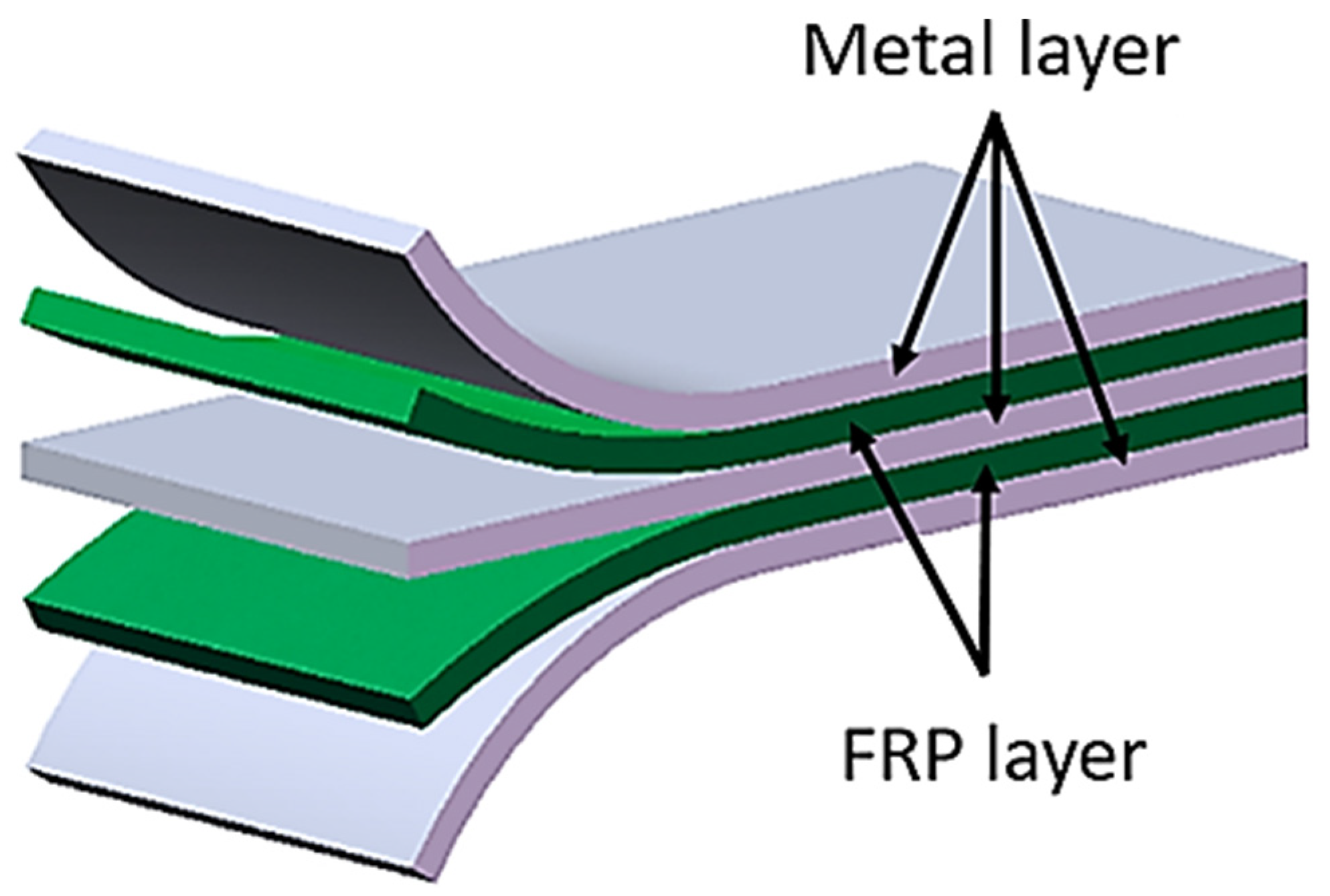
Composite materials such as Fibre Metal Laminates (FMLs) have attracted the interest of the aerospace and automotive industries due to their high strength to weight ratio, but to use them as structures it is necessary to master the manufacturing and wiring techniques of these materials. The process parameters used in multi-material machining, such as drilling and milling, tool geometry, tool coating, lubricants and coolants, must be well established to achieve a successful machining process in FLM materials. Failure of any of these parameters can cause irreparable damage to the material, wasting the process and making it less sustainable. Understanding the failure process is essential to improve the accuracy of the analysis, to supplement the information and to provide a deterrent to adjusting process parameters.

fiber metal laminate drilling milling coolant defects damage

1. Introduction

Composite materials have been gaining visibility for the last few decades due to their advanced properties in comparison to the other material families, specifically in the aeronautic industry, but also with a growing interest in the automobile industry. This tendency began after the Second World War with innovations for military applications, where these materials brought a significant weight reduction in structural design and presented excellent fatigue properties and corrosion resistance as well [1][2].
Fiber-reinforced polymers (FRPs) are heterogeneous composite materials that combine lightweight, stiff, and brittle reinforcing fibers, such as aramid, glass, and carbon (known, respectively, as AFRPs, GFRPs, and CFRPs) bound together by a polymeric matrix (thermoplastic or thermoset) [2]. The fibers, the reinforcing phase, contribute to the improvement of the mechanical properties of the laminated composite, whereas the matrix transfers the load to the inner fibers and at the same time protects them from external damage and provides the composite material with its high fracture toughness [3].
In spite of this, there was a need to improve even further the properties of these materials so they could sustain the harsher conditions existent in aircraft, a requisite satisfied with the appearance of the fiber-metal laminates (FMLs) [4]. These are, by definition, hybrid structures which combine alternate phases of FRPs in the form of plies with thin sheets of a metal alloy, usually aluminum (FRP/Al) or titanium (FRP/Ti) [5][6]. An example of an FML with the fibers incorporated in epoxy resin is observable in Figure 1, which presents a three/two lay-up, since three metal layers alternate with two reinforcement ones.
Figure 1. Fiber metal laminate configuration.
Nowadays, several types of FMLs exist, depending on the chosen metal to use or even the polymer, based on the intended application for the new material. For example, if these are composed of elastomer interlayers, their designation becomes FMEL, for fiber-metal-elastomer laminates [7]. On the other hand, considering just the metal counterpart, the most common FMLs are the CARALL (Carbon Reinforced Aluminum Laminate), GLARE (Glass Reinforced Aluminum Laminate), and ARALL (Aramid-Reinforced Aluminum Laminate) [8][9][10][11]. Apart from the metal and reinforcement constituents, as well as the lay-up configuration in which the metal layers can be outside or inside the multi-material, the direction of the laminate must also be considered, namely, if it is a unidirectional hybrid laminate or a cross ply (woven), as shown in Figure 2.
Figure 2. Classification of FMLs.
Through this union, FMLs combine the durability and easiness of fabrication associated with metal alloys with outstanding specific properties and excellent fracture and fatigue resistance of high-performance composite materials [12][13]. Furthermore, metals lack fatigue strength and corrosion resistance, whereas composites have a low bearing strength and impact strength, in addition to their problem of reparability [14]. Hence, the combination of both materials overcomes the existing negative issues individually. The result is a high-strength, lightweight material with improved thermal, mechanical, and tribological properties [15].
Regarding the manufacturing of multi-materials, this is a difficult process, due to the different properties of the materials to be joined and the relatively weak adhesion between them [16][17][18][19]. Surface treatments can also be executed to enhance the adhesion at the metal-composite interface [20][21][22][23]. Adequate surface treatment of the metallic layer is indispensable to guarantee a good mechanical and adhesive bond between the composite laminates and metal surfaces. This treatment can be mechanical, through abrasion to produce a macro-roughened surface and to remove undesirable oxide layers; chemical, with the immersion of the substrate in an acid solution; or electrochemical, with a coupling agent or dry surface, such as plasma-sprayed coating or ion-beam-enhanced deposition [1]. After the treatment, metal sheets may also be annealed, in order to relieve mechanical and thermal stresses, another step to facilitate the adhesion [24].
Several methods can be employed to achieve the intended configuration, with the most prominent being fusion, chemical bonding (bond dual materials using structural adhesive) [25][26][27], physical and mechanical bonding, such as screwing or riveting (SPR) [19] and friction-based joining processes [28]. Figure 3 presents some of the processing methods used in the fabrication of Carbon Fiber Reinforced Metal Matrix Composites (CF/MMCs).
Figure 3. Processing methods for fabrication of CF/MMCs.
The shown techniques can be of diverse natures. In the solid-state processing, the composites are formed as a result of bonding between the metallic matrix and carbon fiber due to mutual diffusion occurring between the two in solid states at high temperature/pressure. The liquid-based metallurgy methods include processes such as casting and gravity or vacuum infiltration. This technique has as benefits short processing times, high fiber contents and low cost; however, the carbon fibers are likely to separate and float on the surface due to the significant density differences. Finally, the deposition processing consists of depositing the matrix on the fibers through various methods, followed by consolidation of the final product [15].
Alternatively, other fabrication methods also exist, such as forming techniques [29][30], where the cured fiber and resin matrix layers are deformed elastically, and the metal layers are deformed plastically by deep drawing, with a combination of optimized inner glass fiber patches and non-cured FMLs [31][32] or vacuum infusion, where there is no need of an autoclave or press [33][34].
In the case of CFRP/Al and CFRP/Ti stacks, firstly, the metal surfaces are treated for optimal adhesion between the alloy and epoxy resin. After that, they are cured in a hot press, in order to achieve their final configuration, with the adhesive-impregnated fibers prepregs successfully joined with the metallic layers [1].
The multi-material is of the utmost importance to the construction of aircraft due to its enhanced properties, surpassing the other families of materials in specific applications [35]. The CFRP composites are applied in the fabrication of major structural members of aircraft, such as floor beams, frame panels, and a significant portion of the tail sections [36]. Moreover, 25% of the Airbus A380 airframe consists of composites, from which 22% are carbon- or glass-fiber-reinforced plastics and 3% are GLARE [37]. The application of GLARE in the upper fuselage shell of the Airbus A380 resulted in 15–30% weight savings over aluminum panels along with significant improvement in fatigue properties [38]. Considering the Boeing Commercial Airplanes, 30% of the Boeing 767’s outer structure is made from composites, and the Boeing B-787 contains almost 57% of its primary structure built only from composite materials, which confers its wide range of flexibility. In the same way, the blades used in the cooler section of compressor and fan cases, usually employed in aero engines, are manufactured from CFRP, which reduced the assembly total weight by 180 kg and operational costs by 20% [39][40]. Furthermore, CARALL is also used in helicopter struts to absorb shocks, as well as in plane seats. This FML shows extreme fatigue fracture development resistance and outstanding pressure intensity and energy absorption [41]. Its high stiffness and strength with good impact properties also give CARALL laminates a great advantage for space applications [1].

2. Multi-Material Machining Processes

2.1. Multi-Material Process Preparation

The manufacturing process for FMLs is similar to that for polymer composites, using an autoclave process. To produce an FML, six steps must be followed: (i) sheet metal surface preparation, (ii) material deposition: prepreg and metal layers, (iii) mold cleaning and vacuum bag preparation, (iv) curing process, (v) stretching process, and (vi) inspection, usually imaging techniques, and mechanical testing [1].
All these steps must be carefully followed to obtain an FML with excellent mechanical quality, which depends on the correct choice and execution of the material preparation methods. A weak interfacial interaction between the prepreg and the metal can lead to a delamination process in composite structures, which is a major defect. The correct choice of surface treatment is then required to improve the bonding energy between the materials [42].
Adhesive bonding processes such as chemical, coupling agent, dry, electrochemical, and mechanical surface treatments can be used as single or combined methods to produce an FML. All these surface treatments change the surface topography and increase the surface roughness, as well as the interaction between the metal and the bonding site.
Some surface treatments were used as a single method. Kwon et al. [19] used a single method, sanding, a mechanical surface treatment, using three types of sandpaper and different sanding times. They concluded that longer sanding times increased surface energy and improved mechanical adhesion between metal and composite. Drozdziel-Jurkiewicz et al. [20] investigated some aluminum and titanium surface treatments using mechanical, chemical, and electrochemical methods to achieve high adhesion at the metal-composite interface. These surface treatments improve the interfacial fracture toughness of the FML, increase the bond strength and provide high adhesion at the FML interface. The study showed that chromic acid anodization is still the most effective in improving the expected bond strength. In their studies, Thirukumaran et al. [18] used the first step, mechanical abrasion, to create a roughened surface at the macro level and remove an unwanted oxide layer. They then tested the chemical process, also known as acid etching, using two chemical solutions: potassium dichromate and ferric sulfate. The treatment with ferrous sulfate, which contains SO42e ions, had a better performance, promoting pitting, which increased the roughness and favored good adhesion between the substrate surfaces, as indicated by the higher tensile strength values.
Laser and plasma techniques are also used for the surface treatment of aluminum sheets to produce FML. Dieckhof et al. [43] treated AA2024 and AA5028 sheets and found that both techniques allowed the formation of a structured anodic oxide layer, which improved corrosion protection and interfacial adhesion. Park et al. [44] prepared the metal surface by mechanical abrasion, followed by phosphoric acid anodization and alkaline acid etching techniques. They also observed that the rough substrates were essential to improve the bond strength of the metal sheet-prepreg interface. In addition, they understood that selecting different autoclave pressures can influence the quality of the FML, reducing the void content and avoiding premature failure of the FML. Furthermore, Cheng et al. [45] optimized the production of pores on an aluminum substrate. They chemically treated the metal surfaces with three different electrolytes, all containing SO42e ions combined with oxalic acid and/or ferrous sulfate. To improve the interfacial adhesion between the composite and the metal sheet, they also used CNTs for interfacial bridging and final bond strength. They concluded that a rougher substrate surface potentially helps to improve wetting, contact area, and mechanical occlusion of the bonded joint.
Analyzing the surface treatment process in aluminum alloy found in the literature, the combination of mechanical and electrochemical methods is the best used to reach excellent surface preparation. All the papers analyzed showed that a good surface preparation favors an adequate roughness of the sheet metal surface, contributing to an optimal mechanical interlock and excellent interfacial adhesion, thus guaranteeing an FML of sufficient quality so that it can be machined without suffering delamination processes.

2.2. Numerical Simulation Applied to FML Machining

The numerical simulation technique is an economical option used during the development of a product or process. In the numerical simulation, the cost of equipment and man-hours is lower compared to the equipment used in lubrication processes, finishing, and the qualification of the finished product, as it includes the cost of acquisition, maintenance, and man-hours per machine. In this way, numerical simulation helps to reduce costs if it is carried out before experimental tests, reducing the number of tests, and making the choice of parameters more reliable. In addition, numerical simulation can be used to help understand the mechanism of the machining process by predicting cutting forces and temperature effects.
In the aeronautical field, the FML machining process requires a proper design of the processing parameters to avoid the occurrence of various problems and to minimize defects dependent on the process temperature variation, which can be detrimental to the integrity of the parts. These aspects become more critical in dry machining, such as matrix burning, fiber extraction and delamination.
In their work, Parodo et al. [46] monitor the temperature measured on the tool and the workpiece during dry drilling of Al/GFRP (GLARE) and Al/CFRP (CARALL). The influence of cutting speed on the temperature trends was analyzed. In addition, a numerical model was developed to analyze the process of temperature evolution during drilling. The numerical simulation also indicated that the temperature fields are dictated by the thermal properties of the carbon and glass fibers: temperature profiles within the CARALL were found to be smoother than those observed in GLARE. Giasin et al. [38] studied the machinability of GLARE laminate by experimental techniques and analytical simulation. The chosen parameters were the effect of feed rate and spindle speed on the cutting forces and hole quality. A 3D FE model was also developed to help understand the mechanism of drilling GLARE. To evaluate the numerical model’s efficiency, the collected thrust force and torque data were compared, and it was shown that the FE drilling model can predict the cutting forces within acceptable levels. It was the first contribution to the simulation of the drilling process of FMLs. Zitoune et al. [47] investigated the effect of machining parameters and tool geometry on cutting forces, hole quality, and CFRP/Al interface using experimental and numerical simulation. From the experimental study, it was found that the tool-enhanced geometry induced less thrust force compared to the standard one. The numerical analysis was based on the linear fracture mechanics of the CFRP and the plastic behavior of the aluminum with isotropic hardening. The results showed the critical thrust force responsible for the delamination of the last layer as a function of the aluminum thickness and, on the other hand, the maximum shear force responsible for the separation of the CFRP/Al interface was predicted as a function of the aluminum thickness.

2.3. Multi-Material Machining Processes

Conventional machining processes such as drilling, milling, turning, and water jet cutting can be applied to composites, as long as the correct tool design and operating conditions are used. An FML is difficult to machine due to its anisotropic properties, inhomogeneous structure, and high abrasiveness of its constituents. These operations typically result in damage to the laminate such as fiber debonding, spalling, matrix cracking, fiber failure or pullout, and very fast wear of the cutting tool [48][49].
In the aerospace industry, the FML is used because of its lightweight and stability at elevated temperatures. In these composite structures, large numbers of cut-outs and holes need to be produced. As mentioned above, FMLs are basically composed of a sheet of metal, aluminum, or titanium, composite, carbon or glass fiber reinforcement, and a thermoset or thermoplastic matrix. Composites require high speed and low feed, drilling titanium requires low speed and high feed while drilling aluminum requires a balance between speed and feed. Accordingly, the great challenge to drilling the FML is the right choice of parameters processes because of the materials’ constituent properties that also vary with the environmental conditions [50].
Kumar et al. [51] compared the machinability of conventional drilling of hybrid titanium/carbon-fiber-reinforced polymer/titanium (Ti/CFRP/Ti) stack laminates in a single shot under dry and cryogenic conditions. The results indicate that the low temperature affects the hole quality but increases the thrust force due to the increase in the hardness of the Ti sheet at low temperatures. Azwan et al. [52] investigated the effect of different drilling parameters on FMLs, such as the drilling speed, feed rate, and thickness of the FMLs on the strength of composite materials. They concluded that drilling at a lower spindle speed and a lower feed rate generates a higher workload than at a higher speed, for the same feed rate. The thicker FML induces a higher workload compared to the one with less thickness. Zitoune et al. [53] studied the influence of cutting variables on thrust, torque, hole quality, and chip during the drilling of a CFRP/Al stack. They observed that the magnitude of thrust force and torque during the drilling of Al compared to CFRP is doubled at a low feed rate. Hole circularity and surface roughness increase with increasing feed rate. The aluminum layer also has a better finish compared to the CFRP one.
Another machining process to produce holes commonly used in aircraft part finishing is milling. The milling process uses rotary cutters to remove material by advancing a cutter into a part. This method is used as an alternative to drilling these joints with conventional twist drills, named after helical milling, where a milling tool rotates in a helical path and creates a hole [54]. Helical milling has also been investigated for making holes in FMLs, with several advantages such as lower cutting forces, lower heat generation, and easy chip evacuation [55]. The main difference between drilling and helical milling is that in the former, the hole diameter is determined by the tool diameter, whereas in the latter, the hole is defined by a combination of the tool diameter and the helical path, resulting in greater flexibility in the hole diameter [56].
One of the compounds used in the aerospace industry that is difficult to machine is a unidirectional CFRP and Ti6Al4V, due to the hardness characteristics of titanium sheets and the abrasive characteristics of CFRP. They observed diameter variations, which may be due to the different Young’s moduli of titanium and CFRP, as well as variations in surface roughness caused by material-specific chip formation mechanisms [54]. Hemant et al. [57] evaluated the helical hole milling process in GLARE laminates. Although the material and parameters are different from those used by [54], similar process dissimilarities were observed, with variations in hole diameter depending on the material layer, production of discontinuous powdery chips, and surface roughness. Therefore, to obtain an excellent quality finished product, the milling process parameters need to be adjusted to produce holes of uniform diameter throughout their depth, continuous chips in the metal zone, low surface roughness, and a composite layer without delamination.

2.3.1. Comparison of Drilling and Milling Processes Parameters

The different properties of the constituent materials in FMLs are a challenging task when hole-making is needed. Improper selection of the process and process parameters can result in poor surface quality, inadequate dimensional quality, dimensional inaccuracy, or even component failure [58].
However, there are several interrelated factors. The most crucial factors which affect the machinability of the material are cutting forces, tool geometry, materials, coatings, chip formation, analysis of tool wear, hole metrics such as the hole size and circularity error, surface roughness, and burrs formation [59]. Bolar et al. [58] compared two hole-making techniques used in CARALL: drilling and milling. In their study, the two hole-making techniques were evaluated using various performance measures including thrust, radial force, chip morphology, surface roughness, machining temperature, hole diameter accuracy, and burr size. Comparing the results, the authors found some advantages of the helical hole milling process in terms of lower thrust and radial force. The intermittent cutting and convenient chip evacuation and heat dissipation helped to lower the temperature and prevent some material damage. The discontinuous aluminum chips produced by the helical milling process proved to be beneficial, with the holes showing a superior surface finish. However, excessive axial feed in helical milling resulted in tool deformation and chatter, leading to surface quality degradation. Further analysis of the machined surface using microscopic inspection showed that the delamination process occurred when conventional drilling was used. On the other hand, the helically milled hole was free of such defects and showed no signs of delamination. They also found that the formation of oversized holes after the drilling process was incredibly significant. Finally, the exit burr’s height was much lower with helical milling due to the lower thermal impact and lower thrust. Considering all the aspects presented here, it is safe to say that helical milling is a suitable alternative for machining holes in FMLs.
Another study comparing drilling and milling was carried out by Barman et al. [56]. In their work, they evaluated the two-hole machining process in titanium alloy Ti6Al4V material. They carried out the machining tests considering the thrust force, surface roughness, hole diameter, and machining temperature. The morphology of the chips produced and burr formation were also investigated. The magnitude of the force components (thrust and radial force) and the cutting temperature was lower in the milling process, which produced discontinuous powdery chips that evacuated easily without damaging the machined hole surface. The final quality of the holes and the diameter are better in the helical milling process, which produced burr-free holes, contrary to drilling. A similar study using helical milling and drilling techniques to machine AISI D2 tool steel was previously carried out by Iyer et al. [60]. They found that helical milling produced H7-quality holes with good surface roughness compared to drilling. Another comparative study on helical milling of a larger thickness CFRP/Ti stack and its individual layers was conducted by Wang et al. [5]. Their experimental results showed that as the number of holes increased, the cutting forces increased due to tool wear and its dependence on the material type. Indeed, the abrasive nature of the CFRP resulted in an increase in cutting force. The hole edge quality is good while machining the titanium alloy, and low delamination is registered at the tool entry and exit points in the material, indicating that if quality problems of the holes appear, it refers to the milling of CFRP. The hole size was inversely proportional when comparing a single layer to a stack. In the drilling process, with CFRP, smaller hole sizes can be achieved compared to the titanium plate; however, oversized CFRP holes and undersized titanium alloy holes are observed when helically milling stacks.

2.3.2. Lubrication Processes during Machining

During the machining process, a large amount of cutting heat and friction heat can be generated due to the abrasive nature of the material and tool wear, which usually makes the temperature elevate rapidly. Temperature is one of the most important factors affecting the machined hole surface quality, especially for the CFRPs. When drilling CFRPs, the temperature can reach about 150~250 °C, leading to a risk of thermal degradation of the matrix resin, carbonization of thermosetting matrices, the fusion of thermoplastic matrices, and sometimes, burning of the carbon fibers [61]. In addition, the thermal effects can affect the quality of machined holes. These, however, can be minimized using coolants supplied either directly or indirectly to the cutting tool-workpiece interaction zone, to remove part of the generated heat. Nevertheless, the use of coolants adds extra costs for handling, disposal, and environmental impact [62].
The coolants generally used in machining processes are water-oil emulsion, a mixture of a soluble oil cutting fluid and mineral oil lubricant [63], micro-lubrication, also known as minimum quantity lubrication (MQL) [64], cryogenic coolants CO2 [65] and liquid nitrogen (LN2) [66][67], air cooling [55] and vegetable oil [68], among others.
Shyha et al. [63] analyzed the hole quality/integrity after drilling of titanium/CFRP/aluminum stacks under flood cutting fluid water/oil emulsion of 7–8% volume solution and spray mist, a mixture of soluble oil cutting fluid and mineral oil lubricant. Some significant improvements in the machining process were observed. Burr height was generally less than 500 μm, except when spray mist was used. Delamination of the CFRP laminates was significantly reduced due to the support provided by the Al and Ti layers. Surface roughness was significantly lower when using through-spindle cutting fluid compared to spray mist application, especially on the Al section. Spiral-shaped continuous aluminum chips were prevalent, while both short and long helical chips were found with titanium material when cutting under a wet regime. In contrast, the CFRP layer typically produced dusty black composite particles suspended in the soluble oil of the coolant emulsion.
Kumar and Gururaja [69] investigated the cryogenic cooling effects during the drilling of Ti/CFRP/Ti stacks. The parameters such as thrust, torque, delamination, burr height, and surface roughness were considered to investigate the effects of liquid nitrogen (LN2) as a coolant. The results are compared with those obtained from dry drilling of Ti/CFRP/Ti stacks, indicating that torque, the top surface of metal composite interface, exit burr height, and surface roughness decreased when drilling was performed under a cryogenic environment. Nonetheless, thrust force and damage to the lower surface of the metal composite interface are increased under LN2 cooling conditions. Biermann and Hartmann [65] analyzed a cryogenic process cooling with CO2 and found that the chosen coolant improved burr formation in drilling compared to dry machining and resulted in higher sustainability compared to machining with cooling lubricant. Many authors have investigated the influence of the application of cryogenic liquid nitrogen cooling and minimum quantity lubrication (MQL) during GLARE machining. Giasin et al. [70] observed that the use of MQL and cryogenic liquid nitrogen cooling increased the cutting forces; however, both reduced the surface roughness of machined holes, adhesion and built-up edge formation on the cutting tool compared to dry drilling. Examination of the microhardness of the top and bottom aluminum sheets near the hole edges after machining showed that it increased when both coolants were used. Pereira et al. [55] reported some benefits of air-cooling application. It was used to cool the cutting point and to remove the chips, obtaining better results in terms of cutting forces and temperature. The cutting temperature reduction in helical milling was 30%. When drilling the CFRP, the cutting heat becomes lower by increasing the revolution speed. Chips pulverized into small sizes reduce cutting temperature by absorbing heat on the cutting of CFRP composite plate.

2.3.3. Machined FML Defects and Analysis Techniques

Drilling holes in both CRFP and FML can result in material damage as the drill passes through the material. Several types of defects are associated with drilling operations, both at the entry and exit of the hole: dimensional defects, surface roughness and surface integrity problems of the hole wall. Defects induced by machining process conditions include matrix cracking, fiber fracture, debonding, delamination and fiber pull-out. Poor hole quality is the cause of nearly 60% of all scrapped parts [71]. As drilling is often one of the last machining operations, the damage that occurs at this stage results in huge economic losses when near-finished parts have to be scrapped. Understanding and detecting the type, size and location of defects that can occur during drilling operations is important for economical and sustainable process improvement [72]. This damage always occurs combined in hole-surrounding areas.
The great issue in FML drilling operations is the quality of the hole: several defects occur related to the process, mainly on the entry and exit sides of the hole, as well as dimensional and surface roughness issues of the hole wall. The detection of these defects is not trivial, especially when non-destructive methods are used. Several methods have been applied to evaluate the hole quality, such as Computed Tomography (CT)/X-ray Tomography Analysis [72][73][74]; C-Scan [75], Scanning Electron Microscopy (SEM), Stereoscopic Optical Microscopy (SOM), and Energy Dispersive Spectroscopy (EDS) [76]. Nguyen-Dinh et al. [77] analyzed the surface integrity of composites using x-ray tomography after the trimming process. The application of the X-ray technique has enabled the measurement of the craters’ volume compared with surface techniques, such as surface roughness and 3D optical topography. They observed several damaged zones with the formation of craters in the material surface after the trimming process, indicating material pull-out (Figure 4).
Figure 4. X-ray tomography images showing machining damage for a cutting speed of 150 m/min and feed speed of 500 mm/min at a cutting distance of 1.68 m with various depths of scanning of (a) 12 µm, (b) 60 µm, (c) 140 µm and (d) 152 µm.
Pejryd et al. [72] used X-ray computed tomography to detect defects caused by drilling holes in a CFRP. Surface defects and surface properties such as fiber debonding and surface roughness could be easily investigated. Figure 5a shows a typical surface image of a drilled hole based on the reconstruction of the X-ray images. Figure 5b illustrates one way of highlighting the glass fiber material. This technique allows other components to be identified by color. In this case, red color is used to clearly distinguish it from the surrounding material.
Figure 5. (a) A 3D model reconstructed from a CT scan of the drilled hole, outer surface. The hole has a nominal diameter of 9.5 mm and (b) a CT image of the inner wall of a 9.5 mm diameter hole, with glass fiber material highlighted in red.
Wang et al. [78] compared the holes’ quality of CFRP/Al and CFRP/Ti-6Al-4V by Scanning Electron Microscopy (SEM). A two-step helical milling process was proposed and compared with conventional drilling to reduce the damage. In the first step, milling was executed starting on the composite part, and then, in the second step, milling started on the metal part. In the conventional drilling process, they noticed that the damage is superior when the tool entry starts on the composite part, showing many uncut fibers (Figure 6a). The cutting action of the second step eliminates the damage caused by the first step, but the surface next to the hole showed fiber pull-out (Figure 6b). The images showed that the damage induced by the helical milling process in both steps is irrelevant.
Figure 6. Scanning Electron Microscope (SEM) images comparing hole quality of both conventional and helical milling methods (steps 1 (a) and 2 (b)).
The minimization of delamination damage is of great importance because it is a critical parameter that determines the acceptance or rejection of composite components. To achieve this proposal, Bertolini et al. [66] analyzed the hole quality of an Al/CFRP stack obtained by different drilling processes: ultrasonic (UD) and cryogenic (CD), and compared it with dry drilling/regular drilling (RD) using the SEM technique. The feed rates used were 0.05 mm/rev, 0.1 mm/rev, and 0.15 mm/rev. The FML was composed of two layers: one of 5 mm thick aluminum alloy considered the entry face, and the second one composed of a 4 mm thick CFRP sheet, considered the exit face. They were evaluated solely at the exit since the entrance appears defects free (Figure 7).
Figure 7. Entry delamination on the aluminum sheet at varying feed and drilling strategies.
Figure 8 shows the exit face where the delamination process occurred to a greater or lesser extent depending on the variable feeding and drilling strategy. Severe exit delamination occurred solely when drilling tests were conducted under CD, regardless of the adopted feed. This phenomenon can be correlated to the thrust force increase thanks to the hardening of the material as a consequence of the liquid nitrogen application. It is acknowledged that the higher the thrust force, the greater the exit delamination, because the deflection of the FML’s last ply concerns a larger zone.
These techniques already guarantee by themselves the analysis of the damage caused by the machining process, but when combined with other image analysis techniques cited here, they improve the accuracy of the analysis, complementing the information and being a determining factor for adjusting process parameters.
Figure 8. Exit delamination on the CFRP sheet at varying feed and drilling strategies.

References

  1. Sinmazçelik, T.; Avcu, E.; Bora, M.Ö.; Çoban, O. A Review: Fibre Metal Laminates, Background, Bonding Types and Applied Test Methods. Mater. Des. 2011, 32, 3671–3685.
  2. Franz, G.; Vantomme, P.; Hassan, M.H. A Review on Drilling of Multilayer Fiber-Reinforced Polymer Composites and Aluminum Stacks: Optimization of Strategies for Improving the Drilling Performance of Aerospace Assemblies. Fibers 2022, 10, 78.
  3. Singh, A.P.; Sharma, M.; Singh, I. A Review of Modeling and Control during Drilling of Fiber Reinforced Plastic Composites. Compos. B Eng. 2013, 47, 118–125.
  4. Cortés, P.; Cantwell, W.J. The Prediction of Tensile Failure in Titanium-Based Thermoplastic Fibre-Metal Laminates. Compos. Sci. Technol. 2006, 66, 2306–2316.
  5. Wang, H.; Qin, X.; Li, H.; Tan, Y. A Comparative Study on Helical Milling of CFRP/Ti Stacks and Its Individual Layers. Int. J. Adv. Manuf. Technol. 2016, 86, 1973–1983.
  6. Baumert, E.K.; Johnson, W.S.; Cano, R.J.; Jensen, B.J.; Weiser, E.S. Fatigue Damage Development in New Fibre Metal Laminates Made by the VARTM Process. Fatigue Fract. Eng. Mater. Struct. 2011, 34, 240–249.
  7. Roth, S.; Stoll, M.; Weidenmann, K.A.; Coutandin, S.; Fleischer, J. A New Process Route for the Manufacturing of Highly Formed Fiber-Metal-Laminates with Elastomer Interlayers (FMEL). Int. J. Adv. Manuf. Technol. 2019, 104, 1293–1301.
  8. Zhu, W.; Xiao, H.; Wang, J.; Fu, C. Characterization and Properties of AA6061-Based Fiber Metal Laminates with Different Aluminum-Surface Pretreatments. Compos. Struct. 2019, 227, 111321.
  9. Frankiewicz, M.; Ziółkowski, G.; Dziedzic, R.; Osiecki, T.; Scholz, P. Damage to Inverse Hybrid Laminate Structures: An Analysis of Shear Strength Test. Mater. Sci. 2022, 40, 130–144.
  10. Sinke, J. Manufacturing of GLARE Parts and Structures. Appl. Compos. Mater. 2003, 10, 293–305.
  11. Patil, N.A.; Mulik, S.S.; Wangikar, K.S.; Kulkarni, A.P. Characterization of Glass Laminate Aluminium Reinforced Epoxy—A Review. Procedia Manuf. 2018, 20, 554–562.
  12. Sarasini, F.; Tirillò, J.; Ferrante, L.; Sergi, C.; Sbardella, F.; Russo, P.; Simeoli, G.; Mellier, D.; Calzolari, A. Effect of Temperature and Fiber Type on Impact Behavior of Thermoplastic Fiber Metal Laminates. Compos. Struct. 2019, 223, 110961.
  13. Cortés, P.; Cantwell, W.J. The Fracture Properties of a Fibre–Metal Laminate Based on Magnesium Alloy. Compos. B Eng. 2005, 37, 163–170.
  14. Pawar, O.A.; Gaikhe, Y.S.; Tewari, A.; Sundaram, R.; Joshi, S.S. Analysis of Hole Quality in Drilling GLARE Fiber Metal Laminates. Compos. Struct. 2015, 123, 350–365.
  15. Shirvanimoghaddam, K.; Hamim, S.U.; Karbalaei Akbari, M.; Fakhrhoseini, S.M.; Khayyam, H.; Pakseresht, A.H.; Ghasali, E.; Zabet, M.; Munir, K.S.; Jia, S.; et al. Carbon Fiber Reinforced Metal Matrix Composites: Fabrication Processes and Properties. Compos. Part A Appl. Sci. Manuf. 2017, 92, 70–96.
  16. Zhu, W.; Xiao, H.; Wang, J.; Li, X. Effect of Different Coupling Agents on Interfacial Properties of Fibre-Reinforced Aluminum Laminates. Materials 2021, 14, 1019.
  17. Muthu Chozha Rajan, B.; Senthil Kumar, A.; Sornakumar, T.; Senthamaraikannan, P.; Sanjay, M.R. Multi Response Optimization of Fabrication Parameters of Carbon Fiber-Reinforced Aluminium Laminates (CARAL): By Taguchi Method and Gray Relational Analysis. Polym. Compos. 2019, 40, E1041–E1048.
  18. Thirukumaran, M.; Jappes, J.T.W.; Siva, I.; Ramanathan, R.; Brintha, N.C. On the Interfacial Adhesion of Fiber Metal Laminates Using Surface Modified Aluminum 7475 Alloy for Aviation Industries—A Study. J. Adhes Sci. Technol. 2020, 34, 635–650.
  19. Kwon, D.J.; Kim, J.H.; Kim, Y.J.; Kim, J.J.; Park, S.M.; Kwon, I.J.; Shin, P.S.; DeVries, L.K.; Park, J.M. Comparison of Interfacial Adhesion of Hybrid Materials of Aluminum/Carbon Fiber Reinforced Epoxy Composites with Different Surface Roughness. Compos. B Eng. 2019, 170, 11–18.
  20. Droździel-Jurkiewicz, M.; Bieniaś, J. Evaluation of Surface Treatment for Enhancing Adhesion at the Metal–Composite Interface in Fibre Metal-Laminates. Materials 2022, 15, 6118.
  21. Santos, A.L.; Nakazato, R.Z.; Schmeer, S.; Botelho, E.C. Influence of Anodization of Aluminum 2024 T3 for Application in Aluminum/Cf/ Epoxy Laminate. Compos. B Eng. 2020, 184, 107718.
  22. Li, X.; Zhang, X.; Zhang, H.; Yang, J.; Nia, A.B.; Chai, G.B. Mechanical Behaviors of Ti/CFRP/Ti Laminates with Different Surface Treatments of Titanium Sheets. Compos. Struct. 2017, 163, 21–31.
  23. Süsler, S.; Bora, M.Ö.; Uçan, C.; Türkmen, H.S. The Effect of Surface Treatments on the Interlaminar Shear Failure of GLARE Laminate Included AA6061-T6 Layers by Comparing Failure Characteristics. Compos. Interfaces 2022, 29, 1–17.
  24. Bertolini, R.; Savio, E.; Ghiotti, A.; Bruschi, S. The Effect of Cryogenic Cooling and Drill Bit on the Hole Quality When Drilling Magnesium-Based Fiber Metal Laminates. Procedia Manuf. 2021, 53, 118–127.
  25. Robert, C.; Mamalis, D.; Obande, W.; Koutsos, V.; Brádaigh, C.M.Ó.; Ray, D. Interlayer Bonding between Thermoplastic Composites and Metals by In-Situ Polymerization Technique. J. Appl. Polym. Sci. 2021, 138, 51188.
  26. Parmar, H.; Gambardella, A.; Perna, A.S.; Viscusi, A.; della Gatta, R.; Tucci, F.; Astarita, A.; Carlone, P. Manufacturing and Metallization of Hybrid Thermoplastic-Thermoset Matrix Composites. In Proceedings of the ESAFORM 2021—24th International Conference on Material Forming, PoPuPS (University of LiFge Library), Online, 14–16 April 2021.
  27. Banea, M.D.; Rosioara, M.; Carbas, R.J.C.; da Silva, L.F.M. Multi-Material Adhesive Joints for Automotive Industry. Compos. B Eng. 2018, 151, 71–77.
  28. Lambiase, F.; Balle, F.; Blaga, L.A.; Liu, F.; Amancio-Filho, S.T. Friction-Based Processes for Hybrid Multi-Material Joining. Compos. Struct. 2021, 266, 113828.
  29. Ding, Z.; Wang, H.; Luo, J.; Li, N. A Review on Forming Technologies of Fibre Metal Laminates. Int. J. Lightweight Mater. Manuf. 2021, 4, 110–126.
  30. Blala, H.; Lang, L.; Khan, S.; Alexandrov, S. Experimental and Numerical Investigation of Fiber Metal Laminate Forming Behavior Using a Variable Blank Holder Force. Prod. Eng. 2020, 14, 509–522.
  31. Heggemann, T.; Homberg, W. Deep Drawing of Fiber Metal Laminates for Automotive Lightweight Structures. Compos. Struct. 2019, 216, 53–57.
  32. Kalidass, K.; Raghavan, V. Numerical and Experimental Investigations on GFRP e AA 6061 Laminate Composites for Deep-Drawing Applications. Mater. Tehnol. 2022, 56, 107–114.
  33. Dariushi, S.; Rezadoust, A.M.; Kashizadeh, R. Effect of Processing Parameters on the Fabrication of Fiber Metal Laminates by Vacuum Infusion Process. Polym. Compos. 2019, 40, 4167–4174.
  34. Mamalis, D.; Obande, W.; Koutsos, V.; Blackford, J.R.; Brádaigh, C.M.Ó.; Ray, D. Novel Thermoplastic Fibre-Metal Laminates Manufactured by Vacuum Resin Infusion: The Effect of Surface Treatments on Interfacial Bonding. Mater. Des. 2019, 162, 331–344.
  35. Lakshmi Kala, K.; Prahlada Rao, K. Synthesis and Characterization of Fabricated Fiber Metal Laminates for Aerospace Applications. Mater. Today Proc. 2022, 64, 37–43.
  36. Harris, M.; Qureshi, M.A.M.; Saleem, M.Q.; Khan, S.A.; Bhutta, M.M.A. Carbon Fiber-Reinforced Polymer Composite Drilling via Aluminum Chromium Nitride-Coated Tools: Hole Quality and Tool Wear Assessment. J. Reinf. Plast. Compos. 2017, 36, 1403–1420.
  37. Giasin, K.; Ayvar-Soberanis, S. An Investigation of Burrs, Chip Formation, Hole Size, Circularity and Delamination during Drilling Operation of GLARE Using ANOVA. Compos. Struct. 2017, 159, 745–760.
  38. Giasin, K.; Ayvar-Soberanis, S.; French, T.; Phadnis, V. 3D Finite Element Modelling of Cutting Forces in Drilling Fibre Metal Laminates and Experimental Hole Quality Analysis. Appl. Compos. Mater. 2017, 24, 113–137.
  39. Kim, D.G.; Jung, Y.C.; Kweon, S.H.; Yang, S.H. Determination of the Optimal Milling Feed Direction for Unidirectional CFRPs Using a Predictive Cutting-Force Model. Int. J. Adv. Manuf. Technol. 2022, 123, 3571–3585.
  40. Patel, P.; Chaudhary, V. Damage Free Drilling of Carbon Fibre Reinforced Composites—A Review. Aust. J. Mech. Eng. 2021, 370, 1850–1870.
  41. El Etri, H.; Korkmaz, M.E.; Gupta, M.K.; Gunay, M.; Xu, J. A State-of-the-Art Review on Mechanical Characteristics of Different Fiber Metal Laminates for Aerospace and Structural Applications. Int. J. Adv. Manuf. Technol. 2022, 123, 2965–2991.
  42. Min, J.; Hu, J.; Sun, C.; Wan, H.; Liao, P.; Teng, H.; Lin, J. Fabrication Processes of Metal-Fiber Reinforced Polymer Hybrid Components: A Review. Adv. Compos. Hybrid. Mater. 2022, 5, 651–678.
  43. Dieckhoff, S.; Standfuß, J.; Pap, J.S.; Klotzbach, A.; Zimmermann, F.; Burchardt, M.; Regula, C.; Wilken, R.; Apmann, H.; Fortkamp, K.; et al. New Concepts for Cutting, Surface Treatment and Forming of Aluminium Sheets Used for Fibre-Metal Laminate Manufacturing. CEAS Aeronaut J. 2019, 10, 419–429.
  44. Park, S.Y.; Choi, W.J.; Choi, H.S.; Kwon, H. Effects of Surface Pre-Treatment and Void Content on GLARE Laminate Process Characteristics. J. Mater. Process. Technol. 2010, 210, 1008–1016.
  45. Cheng, F.; Hu, Y.; Zhang, X.; Hu, X.; Huang, Z. Adhesive Bond Strength Enhancing between Carbon Fiber Reinforced Polymer and Aluminum Substrates with Different Surface Morphologies Created by Three Sulfuric Acid Solutions. Compos. Part A Appl. Sci. Manuf. 2021, 146, 106427.
  46. Parodo, G.; Rubino, F.; Sorrentino, L.; Turchetta, S. Temperature Analysis in Fiber Metal Laminates Drilling: Experimental and Numerical Results. Polym. Compos. 2022, 43, 7600–7615.
  47. Zitoune, R.; Krishnaraj, V.; Collombet, F.; le Roux, S. Experimental and Numerical Analysis on Drilling of Carbon Fibre Reinforced Plastic and Aluminium Stacks. Compos. Struct. 2016, 146, 148–158.
  48. Dandekar, C.R.; Shin, Y.C. Modeling of Machining of Composite Materials: A Review. Int. J. Mach. Tools Manuf. 2012, 57, 102–121.
  49. Teti, R. Machining of Composite Materials. CIRP Ann. 2002, 51, 611–634.
  50. Krishnaraj, V.; Zitoune, R.; Collombet, F.; Davim, J.P. Challenges in Drilling of Multi-Materials. Mater. Sci. Forum 2013, 763, 145–168.
  51. Kumar, D.; Gururaja, S.; Jawahir, I.S. Machinability and Surface Integrity of Adhesively Bonded Ti/CFRP/Ti Hybrid Composite Laminates under Dry and Cryogenic Conditions. J. Manuf. Process. 2020, 58, 1075–1087.
  52. Azwan, S.; Sahira, N.I.; Abdullah, M.R.; Yahya, M.Y. Investigation on the Effect of Drilling Parameters on Tensile Loading of Fibre-Metal Laminates. In Proceedings of the IOP Conference Series: Materials Science and Engineering; IOP Publishing Ltd.: Bristol, UK, 2019; Volume 670.
  53. Zitoune, R.; Krishnaraj, V.; Collombet, F. Study of Drilling of Composite Material and Aluminium Stack. Compos. Struct. 2010, 92, 1246–1255.
  54. Denkena, B.; Boehnke, D.; Dege, J.H. Helical Milling of CFRP-Titanium Layer Compounds. CIRP J. Manuf. Sci. Technol. 2008, 1, 64–69.
  55. Pereira, R.B.D.; Brandão, L.C.; de Paiva, A.P.; Ferreira, J.R.; Davim, J.P. A Review of Helical Milling Process. Int. J. Mach. Tools Manuf. 2017, 120, 27–48.
  56. Barman, A.; Adhikari, R.; Bolar, G. Evaluation of Conventional Drilling and Helical Milling for Processing of Holes in Titanium Alloy Ti6Al4V. Mater. Today Proc. 2020, 28, 2295–2300.
  57. Hemant, K.; Kona, A.; Karthik, S.A.; Bolar, G. Experimental Investigation into Helical Hole Milling of Fiber Metal Laminates. Mater. Today Proc. 2020, 27, 208–216.
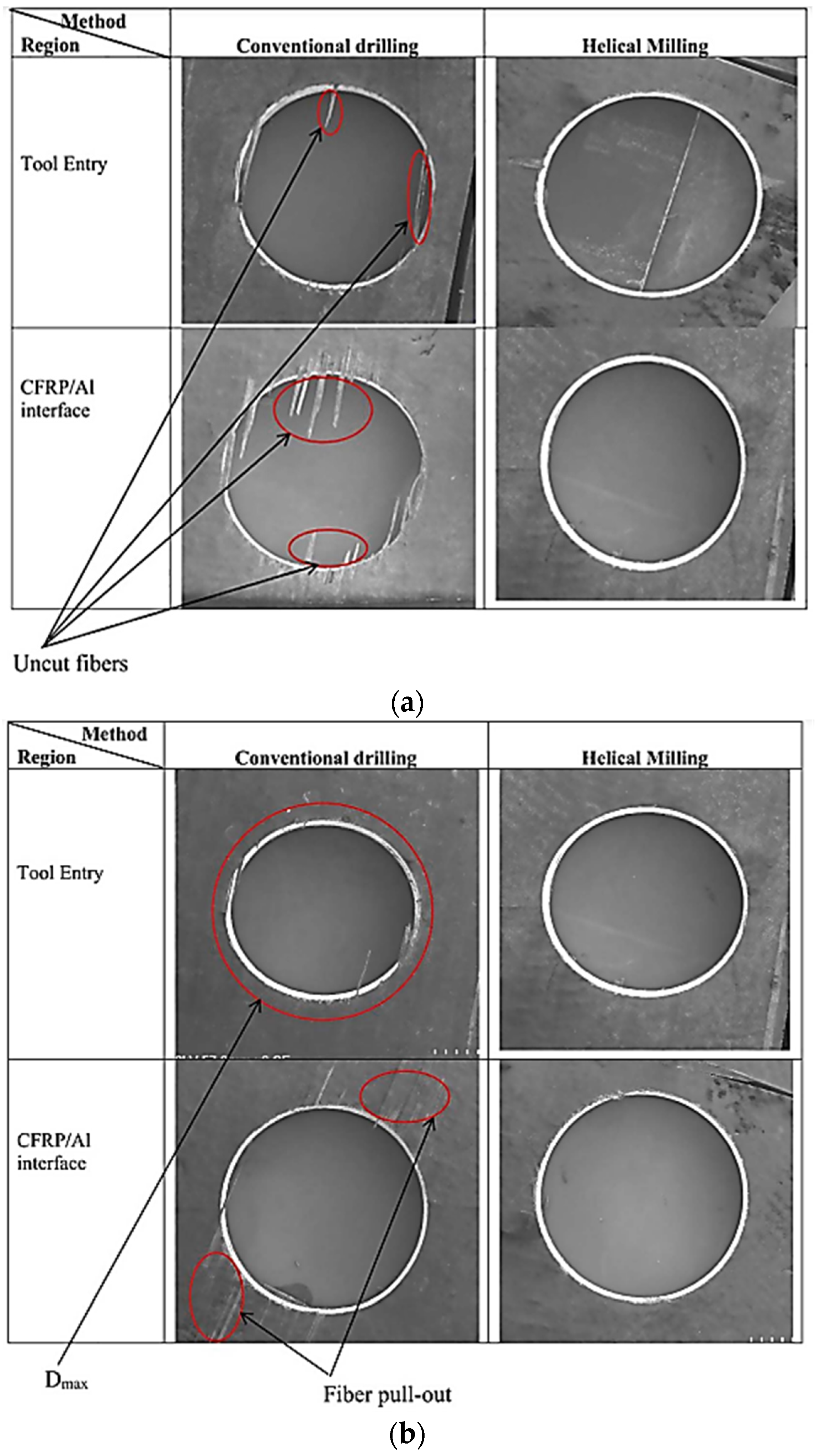
  58. Bolar, G.; Sridhar, A.K.; Ranjan, A. Drilling and Helical Milling for Hole Making in Multi-Material Carbon Reinforced Aluminum Laminates. Int. J. Lightweight Mater. Manuf. 2022, 5, 113–125.
  59. Aamir, M.; Giasin, K.; Tolouei-Rad, M.; Vafadar, A. A Review: Drilling Performance and Hole Quality of Aluminium Alloys for Aerospace Applications. J. Mater. Res. Technol. 2020, 9, 12484–12500.
  60. Iyer, R.; Koshy, P.; Ng, E. Helical Milling: An Enabling Technology for Hard Machining Precision Holes in AISI D2 Tool Steel. Int. J. Mach. Tools Manuf. 2007, 47, 205–210.
  61. Wang, C.Y.; Chen, Y.H.; An, Q.L.; Cai, X.J.; Ming, W.W.; Chen, M. Drilling Temperature and Hole Quality in Drilling of CFRP/Aluminum Stacks Using Diamond Coated Drill. Int. J. Precis. Eng. Manuf. 2015, 16, 1689–1697.
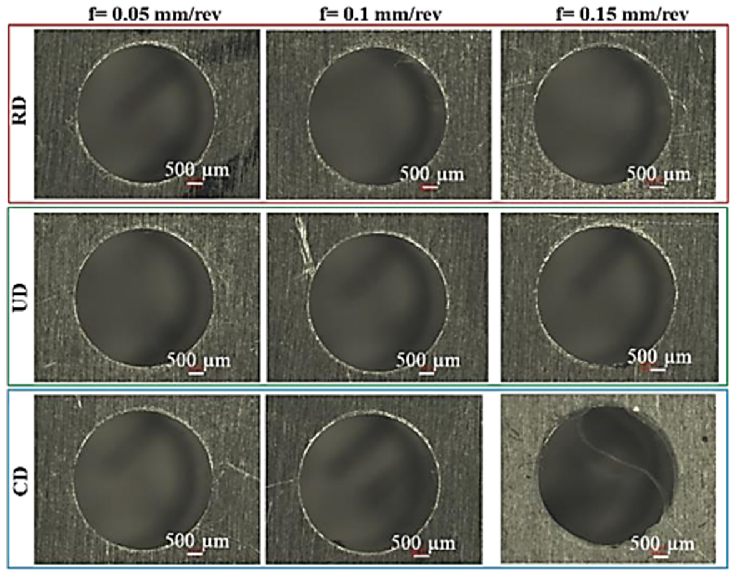
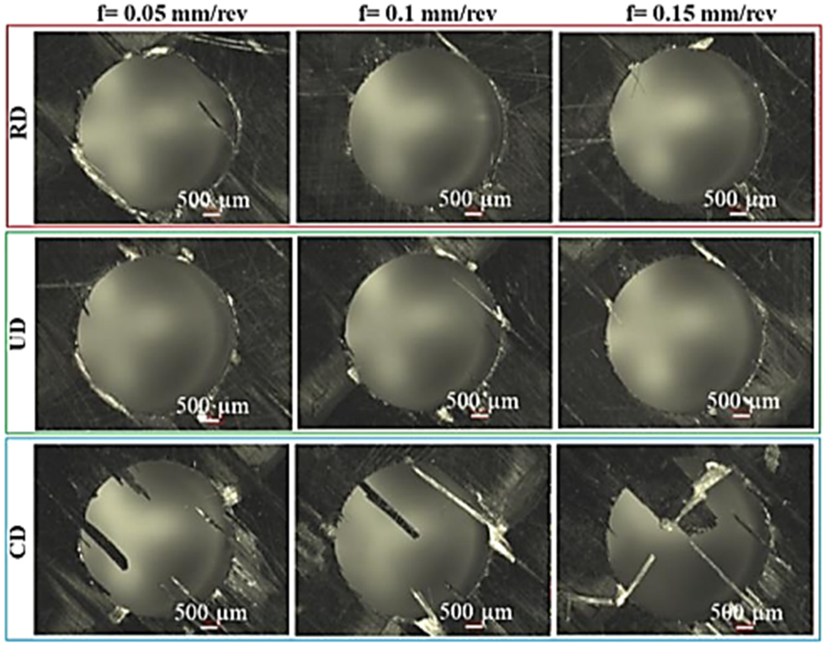
  62. Giasin, K. The Effect of Drilling Parameters, Cooling Technology, and Fiber Orientation on Hole Perpendicularity Error in Fiber Metal Laminates. Int. J. Adv. Manuf. Technol. 2018, 97, 4081–4099.
  63. Shyha, I.S.; Soo, S.L.; Aspinwall, D.K.; Bradley, S.; Perry, R.; Harden, P.; Dawson, S. Hole Quality Assessment Following Drilling of Metallic-Composite Stacks. Int. J. Mach. Tools Manuf. 2011, 51, 569–578.
  64. Boubekri, N.; Shaikh, V. Minimum Quantity Lubrication (MQL) in Machining: Benefits and Drawbacks. J. Ind. Intell. Inf. 2014, 3, 205–209.
  65. Biermann, D.; Hartmann, H. Reduction of Burr Formation in Drilling Using Cryogenic Process Cooling. Procedia CIRP 2012, 3, 85–90.
  66. Bertolini, R.; Alagan, N.T.; Gustafsson, A.; Savio, E.; Ghiotti, A.; Bruschi, S. Ultrasonic Vibration and Cryogenic Assisted Drilling of Aluminum-CFRP Composite Stack-An Innovative Approach. Procedia CIRP 2022, 108, 94–99.
  67. Liu, H.; Birembaux, H.; Ayed, Y.; Rossi, F.; Poulachon, G. Recent Advances on Cryogenic Assistance in Drilling Operation: A Critical Review. J. Manuf. Sci. Eng. 2022, 144, 100801.
  68. Pal, A.; Chatha, S.S.; Sidhu, H.S. Performance Evaluation of the Minimum Quantity Lubrication with Al2O3- Mixed Vegetable-Oil-Based Cutting Fluid in Drilling of AISI 321 Stainless Steel. J. Manuf. Process. 2021, 66, 238–249.
  69. Kumar, D.; Gururaja, S. Investigation of Hole Quality in Drilled Ti/CFRP/Ti Laminates Using CO2 Laser. Opt. Laser Technol. 2020, 126, 106130.
  70. Giasin, K.; Ayvar-Soberanis, S.; Hodzic, A. The Effects of Minimum Quantity Lubrication and Cryogenic Liquid Nitrogen Cooling on Drilled Hole Quality in GLARE Fibre Metal Laminates. Mater. Des. 2016, 89, 996–1006.
  71. Bonhin, E.P.; David-Müzel, S.; Guidi, E.S.; Botelho, E.C.; Ribeiro, M.V. Influence of Drilling Parameters on Thrust Force and Burr on Fiber Metal Laminate (Al 2024-T3/Glass Fiber Reinforced Epoxy). Procedia CIRP 2021, 101, 338–341.
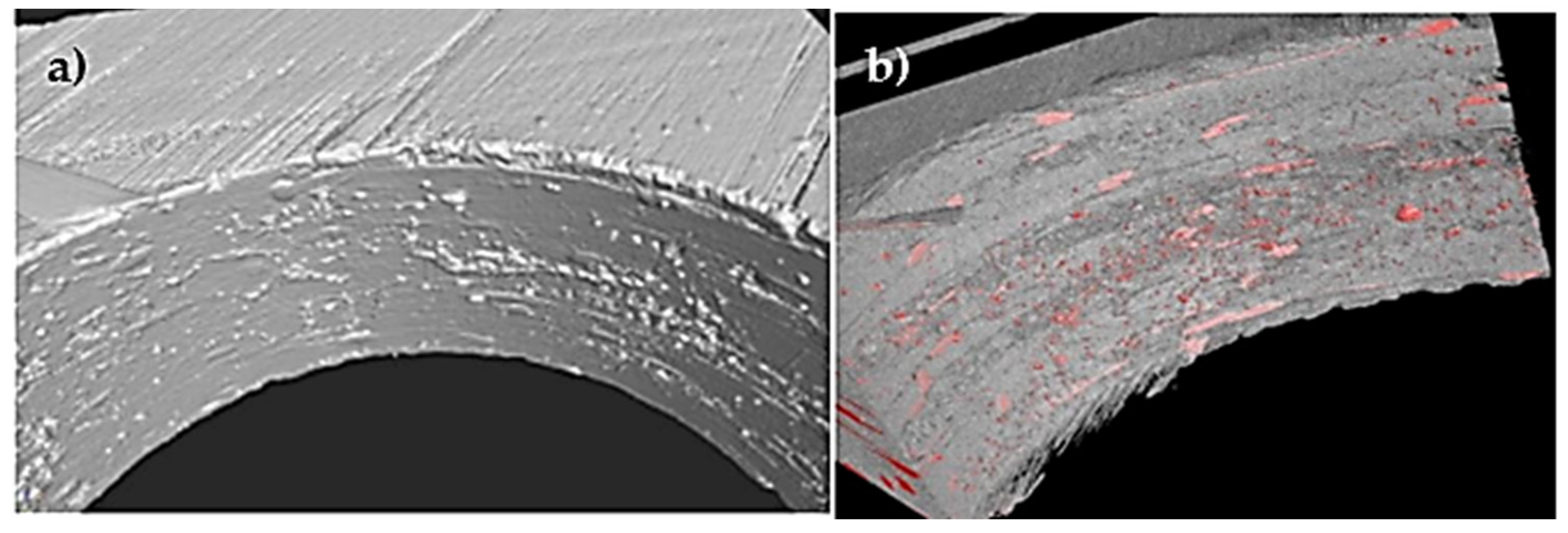
  72. Pejryd, L.; Beno, T.; Carmignato, S. Computed Tomography as a Tool for Examining Surface Integrity in Drilled Holes in CFRP Composites. Procedia CIRP 2014, 13, 43–48.
  73. Saoudi, J.; Zitoune, R.; Mezlini, S.; Gururaja, S.; Seitier, P. Critical Thrust Force Predictions during Drilling: Analytical Modeling and X-ray Tomography Quantification. Compos. Struct. 2016, 153, 886–894.
  74. Saoudi, J.; Zitoune, R.; Gururaja, S.; Salem, M.; Mezleni, S. Analytical and Experimental Investigation of the Delamination during Drilling of Composite Structures with Core Drill Made of Diamond Grits: X-ray Tomography Analysis. J. Compos. Mater. 2018, 52, 1281–1294.
  75. Hocheng, H.; Tsao, C.C. Computerized Tomography and C-Scan for Measuring Drilling-Induced Delamination in Composite Material Using Twist Drill and Core Drill. Key Eng. Mater. 2007, 339, 16–20.
  76. Álvarez, M.; Salguero, J.; Sánchez, J.A.; Huerta, M.; Marcos, M. SEM and EDS Characterisation of Layering TiOx Growth onto the Cutting Tool Surface in Hard Drilling Processes of Ti-Al-V Alloys. Adv. Mater. Sci. Eng. 2011, 2011, 414868.
  77. Nguyen-Dinh, N.; Zitoune, R.; Bouvet, C.; Leroux, S. Surface Integrity While Trimming of Composite Structures: X-ray Tomography Analysis. Compos. Struct. 2019, 210, 735–746.
  78. Wang, G.D.; Melly, S.K.; Li, N. Experimental Studies on a Two-Step Technique to Reduce Delamination Damage during Milling of Large Diameter Holes in CFRP/Al Stack. Compos. Struct. 2018, 188, 330–339.
More
Information
Contributors MDPI registered users' name will be linked to their SciProfiles pages. To register with us, please refer to https://encyclopedia.pub/register : , , , ,
View Times: 693
Revisions: 2 times (View History)
Update Date: 19 Apr 2023
1000/1000
ScholarVision Creations