 +1 credit
| Version | Summary | Created by | Modification | Content Size | Created at | Operation |
|---|---|---|---|---|---|---|
| 1 | Rudolf Holze | -- | 7030 | 2023-02-22 03:31:57 | | | |
| 2 | Rita Xu | -6 word(s) | 7024 | 2023-02-22 03:53:23 | | | | |
| 3 | Rudolf Holze | Meta information modification | 7024 | 2023-02-22 16:07:05 | | |
Video Upload Options
Self-discharge of batteries is a natural, but nevertheless quite unwelcome, phenomenon. Because it is driven in its various forms by the same thermodynamic forces as the discharge during intended operation of the device it can only be slowed down by impeding the reaction kinetics of its various steps, i.e. their respective rates of reaction. This approach should be based on a deeper understanding of the various modes and mechanisms of self-discharge, which in turn depend on the battery chemistry, its mode of operation and environmental conditions. Typical examples from representative battery chemistries are presented and observed effects are reviewed. As an outcome of a better understanding approaches to reduce self-discharge are presented.
1. Introduction
A perfect storage device with ideal properties would keep the stored item forever, at least for long times, without any loss. With presumably very few exemptions at least approaching this aim, such perfect devices do not exist. This frustrating conclusion applies also to devices for energy storage including electrochemical ones. Primary and secondary batteries, supercapacitors and redox flow batteries are all affected [1]. Rare exemptions are reserve batteries wherein the electrolyte solution is stored outside of the cell and redox flow battery when the circulated electrolyte solutions are completely drained from the battery. The concept applied in reserve battery, which have only a very narrow and specific market; is not widely useful; the same applies to RFBs which completely drained can hardly be used for e.g. fast response to changing grid demand. Consequently this entry will focus on the common systems and their self-discharge [2].
Although self-discharge of batteries is addressed in passing in standard textbooks [3] even a major reference work contains just one entry on this fairly significant challenge [4] (see below). Recent comprehensive reviews are not available. In supercapacitors two fundamentally different modes of charge storage in the electrodes may operate. They are substantially different for electrostatic charge storage in electrochemical double layer electrodes and capacitors and for supercapacitors employing superficial redox processes. In the latter case self-discharge resembles that found also in secondary batteries simply because the modes of charge storage in both systems are fundamentally the same. When instead of symmetric devices combining two electrodes of the same type electrodes of different types are combined in asymmetric supercapacitors matters may become even more complicated. A timely review of self-discharge of supercapacitors is available [5]. Given the overlaps between secondary batteries and supercapacitors [6] the various modes of self-discharge will be addressed together; the separation between the two fundamentally different modes will be taken into account in a second step.
A fresh primary battery and a charged secondary battery are in thermodynamic terms in an energetically higher state than in the discharge or depleted state, i.e. the corresponding absolute value of Gibbs energy (free enthalpy ) is larger. Because discharge is a spontaneous process the values carry a negative sign, accordingly describing statements and equations must take this into account. This charged state is far away from thermodynamic equilibrium. The device strives to attain an equilibrium state where the free enthalpy is equal to zero, and the driving force for discharge with release of electric energy is exhausted. In addition to the intended way of moving into this state by controlled discharge further ways are conceivable and unfortunately operative in most cases, they are summarized as self-discharge. The latter is highly unwelcome, but given the thermodynamic facts self-discharge can only be decreased by slowing down kinetics of processes causing self-discharge as much as possible. This applies primarily to chemical reactions contributing to self-discharge; in addition parasitic currents with non-thermodynamic causes can contribute to self-discharge.
Because self-discharge can be described from an electrical engineering point of view as the flow of an unwanted current the operating chemical and electrical effects and descriptions can be summarized into the wish to minimize this unwanted current(s).Parasitic electric currents not related to chemical processes hardly depend on the type of battery (primary or secondary) and battery chemistry (aqueous or non-aqueous electrolyte solution), they will be discussed jointly in a section below. Chemical processes causing self-discharge strongly depend on battery chemistry, beyond the type of electrolyte solution also very much on electrode materials. In following two sections examples will be discussed assigned to the two types of electrolyte solutions (Frequently usage of the term electrolyte appears to include the term electrolyte solution. This saves a word but possibly causes confusion; in addition it oversimplifies the meaning of electrolyte [1][7]). Redox flow batteries based on a very different mode of operation [1][8] are treated in a separate section. Some options to remedy self-discharge or to keep it as low as possible are similar for both aqueous and non-aqueous electrolyte solutions, they are treated jointly in a final section. In the preceding sections only very specific options to reduce self-discharge are discussed. First a general overview will be provided.
The particular importance of self-discharge in setups for energy harvesting with supercapacitors and lithium-ion batteries as storage devices has been discussed elsewhere [9].
2. A General Overview
The energy that can be retrieved from a cell – even when carefully taking into account limited efficiencies caused by overpotentials and other, in part kinetic, effects – will decrease as a function of the duration of storage (shelf time) of the cell. For some systems this loss will be hardly noticeable (shelf times of ten and more years are claimed for some systems with losses in the range of a few percents per year only [1][16]) or will be almost complete already after a few months or even less. These losses tend to be more pronounced at elevated temperatures. Because of the mostly complicated and sometimes only partially known reactions, predictions of temperature dependency of self-discharge are difficult. Instead empirical data yielding Figure 1 have been collected.
Significant temperature effects, i.e. growing self-discharge with increasing temperature, make it e.g. impossible to fully charge a nickel-cadmium battery at temperatures T > 60 °C because self-discharge becomes faster than the desired charging reactions.
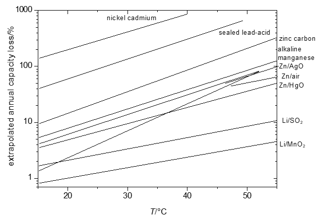
Figure 1. Extrapolated annual capacity losses of selected primary and secondary systems.
Because these disappointing results are similar to the results of intended and proper use (i.e. discharge), this phenomenon is called self-discharge. Strictly speaking the term applies only to complete cells; to self-discharge a single electrode does not make sense. Because many studies of self-discharge focus on processes just at one electrode sometimes the term is applied in an expanded meaning nevertheless, below such studies are included.
Self-discharge’s many causes differ fundamentally. Parasitic electric currents caused by electronically conducting electric pathways between the battery poles inside or outside of the cell may cause self-discharge (See section 3). Currents due to stand-by functions of the device energized by the battery also drain a current from the cell, but they are commonly not discussed in the present context. But more frequent reasons of self-discharge are chemical reactions between active masses and constituents of the electrolyte solution. In case of the primary lithium battery (lithium metal batteries LMB) the negative electrode (anode) is stable only because it coats itself with a protective layer of electronically insulating material (solid electrolyte interphase SEI, see below in section 5) suppressing further chemical reactions between the lithium metal (which is thermodynamically unstable versus basically every electrolyte solution) and its nonmetallic environment. Formation of this SEI consumes some lithium – and the result is a loss of stored energy: self-discharge. During operation the SEI may be partially removed, it must be restored when the load is disconnected. Again a loss of lithium happens; correspondingly some energy has become unavailable. The same applies to the graphite acting as a host for lithium in lithium-ion batteries. The reactions may also simply be called corrosion, but this term would look somewhat out-of-place here. In case of the lead-acid battery it may look more appropriate. Lead being less noble than hydrogen reacts slowly with the battery acid releasing tiny amounts of hydrogen and lead ions. Again stored energy is lost. During charging the dissolved lead ions may be redeposited, but the released hydrogen cannot be recovered easily (see section 4 for options to mitigate or circumvent this problem). A similar problem is encountered with the nickel electrode. NiOOH can react with water (of the alkaline electrolyte solution) yielding oxygen and resulting in lost stored energy.
All reactions associated with self-discharge are chemical or electrochemical reactions. Accordingly rate laws of chemical reaction kinetics apply – and this includes in particular the effect of temperature as already illustrated in Figure 1.
Because most electrochemical storage and conversion systems are thermodynamically inherently unstable or contain compounds therein which are unstable with respect to others, self-discharge is an inherent feature of them, it can only be suppressed as well as possible. Proper cell design and careful selection of materials with well- defined properties and composition have helped frequently to reduce self-discharge. Self-discharge tends to be faster with older cells and after extensive cycling. This can at least in part be due to the formation of electrode reaction products acting as catalysts for unwanted reactions causing self-discharge or degradation of added inhibitors (as present e.g. in the electrolyte solution of alkaline batteries). High-power cells show generally higher self-discharge than high-energy cells (provided a given cell chemistry is available in both forms as reported for lithium-SOCl2-cells), the former cells show higher self-discharge because they contain electrodes with higher surface area and thus more locations for heterogeneous self-discharge processes. A similar straightforward explanation of the obviously higher self-discharge of secondary batteries compared with primary ones is not available because most battery chemistries are either primary or secondary ones (the notable exception is the RAM-system which has already disappeared from the market and which according to the author’s experience shows wildly varying rates). Possibly the structural changes during deposition/dissolution in most electrodes of secondary batteries with associated at least temporarily large electrode surface areas may accelerate self-discharge reactions.
Typical self-discharge data are collected in Table 1.
Table 1: Typical self-discharge rates at room temperature.
|
Class |
self-discharge |
|
|
primary |
Alkali-Manganese cell |
0.5 % per month |
|
Leclanché cell |
0.5 % per month |
|
|
Lithium |
0.5 % per month |
|
|
Lithium/iodine |
< 10 %/10 years |
|
|
secondary |
Lithium-ion |
4 % per month |
|
NiMH |
25 % per month |
|
|
LSD-NiMH |
4 % per month |
|
|
NiCd |
20 % per month |
|
|
RAM |
0.5 % per month |
|
|
For comparison: supercapacitor |
EDLC |
1.8 % per day |
Given the omnipresence of self-discharge with devices for electrochemical energy storage it surprises slightly that review reports, in particular current ones, on this topic are hard to find. Certainly the term shows up frequently in abstracts and research reports. In most cases low self-discharge is claimed for a given device or even a material (although the term seems to be hardly applicable in the latter case). But frequently neither the exact way this claim was verified nor the reason for this improvement are provided. In textbooks self-discharge is addressed [1], but even in major monographs it is mentioned only briefly [10][11][12][13][14] in mostly descriptive ways without too much attention to details in particular of mechanisms and ways of slowing it down. Major reference works provide at least some access to further reading [3][15][16], collections of research reports and reviews again provide some hints [17][18]. Self-discharge of supercapacitors has been extensively reviewed elsewhere [5], because of the apparent merger of secondary batteries and supercapacitors at all levels from the mode of operation and the used materials up to device types [6][19] some overlaps with the present entry are likely.
Self-discharge can also be classified into reversible and irreversible one [18]. In the former case lost energy is restored during a subsequent recharging of the battery, this applies to self-discharge by parasitic currents or some cases of chemical self-discharge reactions. The second, less clearly defined class contains processes wherein material is either irreversibly lost or damaged (e.g. lithium lost in formation of SEI). This classification is not used here.
3. Self-Discharge by Parasitic Currents
A simple cause may be the flow of an electric current even when the device operated with the battery is switched off due to leakage by e.g. electronically slightly conducting traces of dirt on the battery surface or the battery holder between the battery poles as schematically depicted in Figure 2.

Figure 2. Parasitic currents between battery poles by conducting coatings inside and outside a cell.
This flow of current may also proceed inside the cell because of incompletely insulating separators or parasitic electric contacts between active masses (see Figure 2). Because the current “leaks” between the electrodes via unintended Ohmic conduction pathways (thus its name leakage current) it can be represented as an external shunt resistor in parallel to the cell, this helps in modeling. Obviously this type of self-discharge can be suppressed by careful design and operation of the cell and its environment. A standby function may also draw a small current without explicit knowledge of the user; this may be considered in a broader sense also as self-discharge but is obviously beyond the scope of this research.
4. Self-Discharge in Aqueous Batteries
In a battery energy is stored by using electric energy to drive a chemical transformation, the obtained materials are “richer in energy” (the absolute value of the Gibbs energyis larger) than the starting materials. As an example, the charging reaction at the negative electrode of a lead-acid battery shall be considered:
PbSO4 + 2 e- + 2 H+ → Pb + H2SO4 (1)
Upon discharge the process is reversed:
Pb + H2SO4 → PbSO4 + 2 e- + 2 H+ (2)
As an alternative the following reaction is conceivable
Pb + H2SO4 → PbSO4 + H2 (3)
The reaction at the positive electrode can be
PbO2 + H2SO4 → PbSO4 + H2O + ½O2 (4)
Although lead is less noble than hydrogen this reaction (3) is slow because lead is a poor electrocatalyst for hydrogen evolution, a similar argument applies to the positive electrode (reaction (4)), which thermodynamically is also not stable versus the electrolyte solution [20]. Dioxygen present in the electrolyte solution of open cells can react at the negative electrode according to
Pb + ½ O2 + H2SO4 → PbSO4 + H2O (5)
In chemical terms this can be called corrosion, in a battery this is a loss of energy and only welcome as a measure limiting hydrogen evolution during overcharge in valve-regulate lead-acid batteries (VRLA). Otherwise it is self-discharge. The rates of the mentioned reactions depend on temperature and acid concentration; with higher temperature and acid concentration the rates increase. The rate also depends on the state-of-charge SoC. A fully charged VRLA cell may self-discharge from 100 % to 90 % SoC within one to two weeks, whereas at the same temperature self-discharge from 20 % to 10 % may last ten or more weeks [16]. Self-discharge is lower in sealed cells with a small amount of phosphoric acid added into the sulfuric acid electrolyte solution (the cells are of the “starved type”, there is no free solution) [21]. The slower self-discharge is attributed to the presence of phosphoric acid, the expander in the negative electrode does not affect self-discharge. The antimony-free grids show corrosion, i.e. self-discharge, only at cell voltages > 2 V.
Electrochemically active impurities in the electrodes and/or the electrolyte solution like Fe2+/Fe3+-ions may establish a redox shuttle mechanism as depicted in Figure 3.
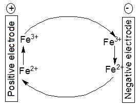
Figure 3. Scheme of an iron ion redox shuttle mechanism
The following reactions result in self-discharge:
At the positive electrode
PbO2 + 3 H+ ++ 2 Fe2+ → PbSO4 + 2 H2O + 2 Fe3+ (6)
and at the negative electrode
Pb ++ 2 Fe3+ → PbSO4+ H++ 2 Fe2+ (7)
yielding the cell reaction
PbO2 + Pb+ 2 H2SO4 → 2 PbSO4 + 2 H2O (8)
The cell reaction is the already stated process during regular discharge. Both parasitic electrode reactions proceed as long as the respective electrode potentials enable them. The impurity ions themselves are not consumed; the undesired process may go on. Once discharge goes on the electrode potentials move closer to each other, consequently the electrode potential may not be favorable that much for the parasitic reactions any more. Additives to electrodes and/or electrolyte solutions (like the expanders in lead-acid batteries) may decompose during operation, leaving products which either act as catalysts for reactions like hydrogen evolution contributing to self-discharge or may establish shuttle mechanisms. Antimony alloyed into the grid for the positive electrode in a lead-acid battery may corrode and get into the battery electrolyte solution finally deposited onto the negative electrode. There it catalyses hydrogen evolution thus decreasing charging efficiency and increasing self-discharge. Instead of antimony calcium has been suggested resulting in lower gas evolution and self-discharge [14][16]. Substitution comes with new problems because of the loss of other beneficial effects of alloyed antimony [16].
The state of charge and consequently self-discharge of a nickel oxide electrode can be monitored with electrochemical impedance measurements. According to results exposure of the electrolyte solution with the immersed electrode to hydrogen results in faster self-discharge [22]. Based on the results the following overall reaction has been proposed [23]:
NiOOH + 1/2 H2 → Ni(OH)2 (9)
NiOOH used as the positive electrode in several aqueous secondary batteries is a good mixed-ion conductor readily establishing equilibrium with its aqueous environment [10]. The reaction with water results in incorporation of hydrogen into the electrode and oxygen evolution with a decrease of the electrode potential: self-discharge happens:
2 NiOOH + H2O → 2 Ni(OH)2 + ½ O2 (10)
The highly oxidizing capabilities of positive electrode materials like PbO2 or nickel oxide may also result in chemical oxidation of cell components like the separator yielding decomposition products and loss of stored energy (self-discharge). Separators made of polyamide (Nylon®) may also undergo chemical reactions with oxygen and hydrogen in the cell resulting in decomposition and/or degradation [16]. Use of more stable other polymers, e.g. a composite of polypropylene and polyethylene with some surface treatment, help in reducing this form of self-discharge [16].
Lower self-discharge of NiMH-batteries has been observed with cobalt-free negative electrode materials replacing the conventional AB5-type alloys [23]. Such alloys containing vanadium may support self-discharge because of the solubility of vanadium enabling establishment of a redox shuttle process (see Figure 3) and associated self-discharge [16], further details of reduced self-discharge have been reviewed [16].
The iron electrode suggested for various secondary cells (e.g. the Fe-Ni-cell) shows significant corrosion resulting in self-discharge of the assembled cell because of its electrode potential lower than that of the hydrogen electrode [24]. In addition to fast self-discharge Coulombic efficiency during charging is low because of the competing hydrogen evolution [25][26][27][28]. Because of the basically attractive features of the iron electrode attempts to mitigate self-discharge have been reported. Addition of FeS and PbS has resulted in increased storage capacity and inhibition of self-discharge, 1 wt.% of PbS was most effective [29]. Formation of metal sulfites which in turn inhibit hydrogen formation and the presence of lead were identified as the causes.
Zinc employed as a negative electrode in several primary batteries with aqueous electrolyte solutions shows corrosion caused by its electrode potential negative to that of the hydrogen electrode. This basically causes hydrogen evolution, i.e. self-discharge. Figure 4 shows schematically the various options for slowing down corrosion, i.e. self-discharge.
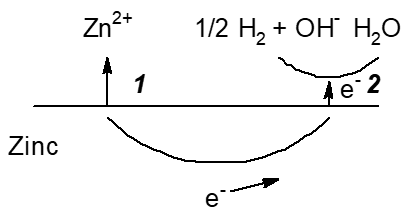
Figure 4. Scheme of reactions during corrosion, i.e. self-discharge, of a zinc electrode in an aqueous electrolyte solution with options to decrease it. 1: Slowing down zinc oxidation (the anodic partial reaction) and dissolution, 2: Slowing down hydrogen evolution (the cathodic partial reaction).
In primary cells this has been a major challenge with all types of zinc battery chemistries as discussed above. Some positive electrode materials like HgO used earlier in some primary batteries with negative zinc electrodes show some solubility in the alkaline electrolyte solution resulting in deposition of mercury at the negative electrode and associated self-discharge [30]. This deposit slows down hydrogen evolution (see Figure 4: Option 2, for obvious reasons this process is sometimes called gassing) and thus self-discharge by zinc corrosion. Until the ban of the use of mercury in batteries this was a common additive, now this is history. Instead various other corrosion inhibitors are added to the electrolyte solution, the use of high-purity zinc as well as small amounts of alloyed elements are further options.
A secondary zinc-air battery with a negative zinc electrode faces the common problems encountered with this metal in aqueous electrolyte solutions in primary batteries. In a zinc-air cell remedies suitable for this type of cell are required. Coating the negative zinc electrode with polyaniline for use in a cell with a gelled aqueous KOH-electrolyte solution has been examined successfully [31]. Prevention of the direct contact between the zinc electrode and the aqueous electrolyte solution afforded by the layer of PANI has been identified as major task of this coating [32]. A quaternary ammonium-functionalized polyvinyl alcohol membrane as almost neutral electrolyte was employed in a solid state zinc air battery with much reduced self-discharge [33]. Dendritic deposition of zinc causes several detrimental effects [34]. Dendrites may in the extreme case penetrate the separator, contact the positive electrode and cause a short-circuit. Less dramatic is the associated increase of surface area by this shape change with enhanced self-discharge
A further application option for the zinc electrode in a self-stratified battery with a negative zinc electrode at the bottom in an aqueous electrolyte solution and an organic electrolyte solution with an organic redox system insoluble in the aqueous solution and a porous carbon electrode as current collector on top has been proposed [35]. For improved electrode kinetics and thus higher current capability the latter electrode is rotating. Self-discharge is basically eliminated because the redox system at the positive electrode is soluble only in the top organic electroyte solution. The cell concept goes back to the crowfoot cell popular in the 19th century with American and British telegraph companies.
The use of aluminum as a basically attractive negative electrode material with aqueous electrolyte solutions has been hampered by its instability in such solutions caused by its negative electrode potential driving hydrogen evolution by corrosion. For diminished self-discharge additives to electrolyte solutions, alloying with several further elements [16][36] and replacement of the aqueous solution have been suggested.
Modeling of self-discharge has been applied for a better understanding of ongoing processes and for prediction of cell behavior of e.g. nickel/hydrogen cells [37].
5. Self-Discharge in Non-Aqueous Batteries
When the reduction potential of the negative electrode material and/or the oxidation potential of the positive electrode material (the respective terms anode and cathode may work in case of a primary battery, they become confusing when inspecting a secondary battery and should thus be avoided as suggest by Huggins years ago [10][11]) are outside of the window of electrochemical stability of the electrolyte or the electrolyte solution (for a critical examination of this concept see [38]) decomposition either of the solvent and/or the electrolyte (salt) may proceed at the positive and/or negative electrode. The effect will be self-discharge. In a few cases materials can be used with aqueous electrolyte solutions nevertheless, provided the respective reactions are very slow (see above, lead acid battery negative electrode, zinc battery negative electrode). In most cases this solution, which is actually not a solution but just tinkering, is not applicable. Primary and secondary batteries with alkali metal negative electrodes, which can decompose the electrolyte (solution) reductively, are the most popular examples. Various metal oxides, which afford this decomposition oxidatively, are the popular corresponding positive electrode examples.
Nonaqueous electrolyte solutions employing suitable organic or inorganic solvents, ionic liquids, gelled electrolyte or solid electrolytes are the frequently applied escape. Even many of these ionically conducting systems are thermodynamically not stable with respect to the negative electrode as well as to many highly oxidizing positive electrode materials. Because of the high reactivity of these electrode materials and the correspondingly large driving forces of both the wanted discharge reactions as well as the unwelcome self-discharge reactions slowing down kinetics is no solution. Instead protective layers are formed, which separate the active material from the electrolyte (solution). The solid electrolyte interphase layer (SEI) formed on the surface of a lithium electrode is a classical example. It is the result of reductive decomposition of various components of the electrolyte solution, the actual composition and its properties have been the subject of intense research as reviewed elsewhere [39][40][41], for some typical insights see [42]. Some positive electrode materials are also capable of decomposing electrolyte solution constituents resulting in the formation of a layer (CEI, cathode electrolyte interphase), this phenomenon has been studied less frequently, reviews are available [43][44]. In a typical study a CEI on copper nitroprusside (Cu[Fe(CN)5NO] several electrolyte solution decomposition products were identified [45]. CEI’s will have growing importance with high-voltage cells using positive electrode materials with ever higher oxidation capability.
Formation of these layers, which may also be formed with other ionically conducting phases between the electrodes as mentioned above, consumes active material, it is thus self-discharge. Fortunately it will happen only once when the active masses are brought into contact with the electrolyte solution for the first time. Subsequently these layers act as ion conductors, and ideally they shall remain on the active mass unchanged during repeated charge/discharge cycles or, in case of a primary battery, during intermittent discharge. When left undisturbed growth of the layer will slow down with storage time, self-discharge will decrease [16]. Some of these layers have a rather high Ohmic resistance (e.g. those on lithium metal in contact with electrolyte solutions based on SO2Cl2 or SOCl2 or SO2 dissolved in acetonitrile) causing a voltage collapse when discharge is turned on, the “voltage delay”. In particular when high discharge currents are drawn the SEI will crack and will be damaged more or less; in the previously addressed case the cell voltage will be restored. Thus it will be rebuilt when the load is disconnected, requiring further material from the cell inventory – more self-discharge. Self-discharge of different carbon materials has been compared at various temperatures [46], higher self-discharge was found – as expected with respect to the discussion above – to be faster at elevated temperatures and with materials having a larger surface area. The rate of SEI formation – part of the self-discharge – was independent on carbon material at lower temperatures but differed significantly with material at elevated temperatures. Self-discharge of cells with SO2Cl2 is higher than with SOCl2 [16].
In case of secondary batteries numerous cell designs and cell chemistries use host materials in the electrodes for metal (ion) insertion/deinsertion which may show volume and shape change during charge. This will negatively affect the deposited SEI/CEI-layers by e.g. cracking or shedding, and again initiate more layer formation with associated material consumption – self-discharge.
Intrinsically conducting polymers like polyacetylene as active electrode masses may cause decomposition and thus self-discharge of organic solvent-based electrolyte solutions [47]. In the latter case products of solvent decomposition further mediate and accelerate self-discharge of the p-doped (charged) polyacetylene. Further options like reaction of the p-doped polymer with impurities or intrinsic instabilities of the polymer have been considered [48]. Quite differently polypyrrole was not found to “self-discharge” in its oxidized state when brought into contact with an electrolyte solution [48]. Obviously its oxidizing capability was insufficient for any reaction with the electrolyte solution. Only in a complete cell, i.e. with the negative lithium electrode present, self-discharge was observed. It was consequently attributed to some mobile and redox-active species generated by reaction of lithium with the electrolyte solution. Elsewhere a composite of polypyrrole and polyethylene oxide showed better performance than polyrrole alone, in terms of storage capability, but much poorer charge retention, i.e. higher self-discharge, for unknown reasons [49]. By comparison lowest self-discharge was observed with polyaniline studied as a positive electrode, this was tentatively related to lower sensitivity of the polymer towards oxidation [50].
Some electrode materials or reaction intermediates present only temporarily during electrode reactions show significant solubility and may thus diffuse to the other electrode and react directly with the active mass. This self-discharge is frequently encountered with secondary batteries employing sulfur as the positive electrode mass [51]. The mechanism is commonly name redox-shuttle mechanism, it causes self-discharge only during charging of the battery whereas further parasitic reactions of soluble polysulfides may affect the cell negatively at all times [52][53]. A simplified reaction scheme is shown in Figure 5.
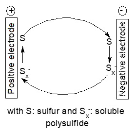
Figure 5. Scheme of a redox shuttle mechanism
Because sulfur itself shows only low solubility in most employed solvents instead of sufur polysulfide anions with different states of oxidation may diffuse. This shuttle is still a major hurdle in development of lithium-ion batteries which otherwise show very promising performance data. This mechanism will of course also show up with other negative electrode metals like calcium [54]. There are numerous studies aiming at reducing this process, for reviews see [53][55][56]. Basically this mode of self-discharge can be diminished by keeping the soluble intermediates in the possible electrode or reduce the solubility of the intermediates in the used electrolyte solution. Adding redox mediators for improved performance of lithium-oxygen batteries causes the same redox-shuttle processes and associated self-discharge [57], a Nafion®-based membrane separator with high lithium-ion selectivity is the obvious remedy. Broader perspectives of the associated problems for lithium-oxygen batteries including self-discharge have been reviewed [58].
Mixed conduction membranes have been suggested as another option to suppress the polysulfide shuttle [59]. Among further possible remedies is physical confinement (trapping) of the elements as well as possibly mobile intermediates, for examples see [74]. In a similar approach multilayer encapsulation of sulfur has been proposed [60], this can be traced back to earlier and initial work aimed at better sulphur utilization and reduction of self-discharge [61]. Adsorption (trapping) of polysulfides, possibly combined with accelerated conversion of these species into less soluble ones has been studied [62]. Catalytic options to meet the polysulfide shuttle challenge have been reviewed [63][64]. Use of an interlayer adsorbing polysulfides and accelerating their transformation into less detrimental species has been suggested [65]. Further similar approaches have been proposed elsewhere [66][67]; options to control polysulfide diffusion and thus reduce self-discharge have been compared [68]. The influence of functional binders on self-discharge of Li/S-batteries has been addressed [69]. Reviews of the polysulfide-related challenges in lithium-ion/sulphur batteries are available [70][71], self-discharge has been stressed as a still significant bottleneck when comparing lithium-ion/sulphur batteries with other lithium-ion systems [72].
Basically the same problems of increased self-discharge are found when substituting selenium for sulfur or using SeS2 [73].
Measurement of self-discharge as a tool to monitor ageing of lithium-ion batteries has been proposed [74]. Among the various options to keep detrimental effects of overcharge of lithium-ion batteries small the addition of redox shuttles has been proposed [75], quite obviously these additives may contribute to self-discharge according to the mechanism sketched above, in particular when their action becomes effective already at cell voltages and thus electrode potentials within the range of ordinary cell operation.
A similar shuttle mechanism is found with the antipolar mass in nickel-cadmium electrodes [9]. In case of deep discharge evolution of hydrogen, which might pass to the other electrode oxygen evolving at the positive electrode is reduced at the cadmium of the antipolar mass. Self-discharge is not caused.
Utilization of the redox coupleas the negative half-cell of a battery has been hampered by its chemically aggressive behavior, in particular the lack of a suitable current collector [76]. Addition of LiCl resulted in the formation of some coordination species inhibiting intercalation of the tetrachloroaluminate in the negative current collector; in addition this enables the use of established positive electrode materials from lithium-ion batteries resulting in a cell with minimal self-discharge.
In high temperature liquid metal batteries with molten salts as electrolyte between the two molten metallic electrodes [1][77] self-discharge is frequently caused by dissolution of an electrode metal in the molten electrolyte [78][79]. Changing the composition of the molten electrolyte or the used metals or metal alloys has been reported as option [79][80], using a solid ion conducting electrolyte instead of the molten electrolyte is a further possibility which unfortunately may cause new challenges regarding lower ionic conduction, wetting, costs and mechanical stability.
A general feature of high-temperature batteries is the need to maintain their operating temperature by heating when the battery stands idle and no Joule heating generated by the flow of current in the operating cell serves this purpose [1][80]. The heat needed for this upkeep may be taken from the cell, this amounts to thermal self-discharge.
6. Self-Discharge in Redox Flow Batteries
In a redox flow battery RFB two half cells containing dissolved redox systems with different redox potentials combining into the cell voltage are connected via a suitable separator [1]. Both solutions must be kept separate to avoid chemical reactions between the active ingredients resulting in discharge of the cell. In most device designs this separation is established by inserting a semipermeable ion-conducting membrane [8]. Further options like porous separators for systems with larger redox ions are under consideration.
Self-discharge in RFBs can be caused by ion-crossover through the separator/membrane, i.e. unwanted mixing of redox components resulting in direct chemical reactions and undesired heating of the cell. Further processes causing self-discharge are chemical reactions between redox constituents and cell components, i.e. oxidation of electrode materials by highly oxidizing compounds in the positive electrode half-cell. Because the electrolyte solutions in the half-cells will be circulated by external pumps (in case of hybrid systems where a solid electrode is combined with a redox-half-cell there may be one pump only) running the pumps even when the RFB is in idle condition, will cause energy consumption, energy is drained from the amount stored in the device. This will also result finally in “self-discharge”. Further auxiliary devices needed to monitor and control proper operation of the RFB will also cause energy consumption. Similar to devices monitoring the state of a battery module or a battery pack, this will also result in consumption of electrical energy most likely drained in all cases from the energy initially stored in the device.
Self-discharge caused by ion crossover is closely related to imperfections of the used separator, whether it is a semipermeable membrane or a highly porous material. In case of e.g. an all-vanadium RFB the membrane should completely prohibit transport of vanadium species and water but permit transport of other charge carrying species involved in charge balancing like H+, , and . A perfect membrane does not exist; consequently researchers have tried to identify most suitable membranes and have tried to improve their properties (perm selectivity, Ohmic resistance, chemical and mechanical stability). Because the currently most frequently used membranes based on perfluorosulfonated or –carboxylated PTFE tend to be expensive, price considerations, i.e. getting cheaper membranes, add a further dimension to the engineering and chemical challenges [68]. Improved perm selectivity of a Nafion®-based membrane (and thus lower self-discharge) can be afforded by incorporating inorganic nanoparticles [81][82][83] and by further modifications of the membrane [8][84]; this includes application of additional barrier layers [85] and double layer membranes [86]. Use of an anion exchange membrane containing silica nanoparticles has been suggested as a further option reducing self-discharge by ion crossover and also reducing costs [87].
Modeling of self-discharge of an all-vanadium RFB assuming a diffusion rate of vanadium ions depending on diffusion coefficient, partition coefficient and concentration gradient was found to provide a good description of the experimentally observed changes [88]. A further modeling approach taking into account further experimental data as well as other processes contributing to self-discharge has been developed aiming at its inclusion in the cell control software with particular regard to the need of cell rebalancing [89]. In a theoretical study of self-discharge-related reactions in an all-vanadium RFB polymerization reactions of vanadium ions and participation of multivalent ions have been highlighted [90].
A further option to reduce ion crossover is the use of redox-active electrolyte components large enough in the solvated state to slow down or even inhibit their unwanted passage through the membrane. Numerous materials have been proposed, polyoxometalates [91] are among them. Self-discharge by ion crossover has also been observed when using a cerium-based half-cell [92].
Oxidation of cations in the negative half-cell of e.g. an all-vanadium RFB by dioxygen from ambient air in an essentially open system may also result in self-discharge [93]. The suggested remedies are obvious: Smaller surface area of the electrolyte solution reservoir exposed to air is obvious, higher electrolyte concentrations apparently also slow down oxidation of V(II) by dioxygen.
In practical setups frequently several RFBs are connected in series. Distribution of the electrolyte solution with manifolds etc. results in shunt currents, this in turn causes self-discharge. It has been modeled [94]. Growing self-discharge with increasing number of connected cells does not come as a surprise, because the larger overall voltage drop provides a higher driving force. An extensive study of a practical 200 kW/400 kWh all-vanadium RFB has been reported [95]. Up to 24 % of the delivered energy was consumed by peripherals necessary to operate the RFB, separate numbers directly indicative of self-discharge were not provided. When the RFB was kept in an operational state needed for fast response (spinning reserve, primary operating reserve) up to 80 % of the charge were lost in 48 h.
In addition to the prototypical RFB with two circulated liquid electrolyte solutions with a membrane or another separating item other electrode combinations have been proposed, for an overview see [1,8]. Among them is the combination of a solid metal negative electrode with a second half cell with a circulated dissolved electrolyte, another one is the use of two solid electrodes with an electrolyte solution as suggested in [96] with a negative cadmium and a positive lead dioxide electrode. The cell reaction is
PbSO4 + 2 H2O + Cd2+ ⇄ Cd + PbO2 + 4 H+ + (11)
with an aqueous electrolyte solution of 1 M CdSO4 and 2 M H2SO4. Self-discharge is caused by reduction of water by the cadmium electrode thermodynamically unstable in this electrolyte solution with associated hydrogen evolution. The rather high overpotential of the hydrogen evolution reaction at the cadmium electrode already limits self-discharge, electrolyte solution additives (DPE-3) have been suggested for further inhibition [97]. A similar design with a negative zinc electrode faced even more serious self-discharge by hydrogen evolution at the negative electrode [97].
Half-way between the two cell principles addressed above are RFBs with a solid electrode combined with another half-cell containing a redox system. The zinc/bromine or zinc/iodine systems are typical examples. Self-discharge in these cells proceeds by formation of local elements on the negative zinc electrode involving dissolved impurities and chemical reactions between the halogen and zinc possible when the separator does not work perfectly [98].
7. Remedies: Ways to Limit Self-Discharge
Numerous approaches to limit or slow-down self-discharge have already been addressed above when presenting examples. Because electrode reactions are by definition heterogeneous processes at the electrode/electrolyte interface researchers have tried to make this interface as large as possible. Because most self-discharge reactions are also heterogeneous processes any increase of surface area will help both the wanted and the unwanted electrode reactions. When having achieved an optimized electrode morphology in terms of surface area and porosity this should not change too much during charge/discharge (e.g. by disintegration of active mass particles caused by volume expansion or pulverization initiated otherwise) because this will also enhance self-discharge; in addition it might consume active material during formation of surface layers.
Additives in the electrolyte solution have been applied with both aqueous and non-aqueous electrolyte solutions. Their task varies from inhibition of parasitic electrode reactions (“corrosion”) to binding unwanted and detrimental impurities introduced via the electrodes and/or the electrolyte solution to catalyzing processes participating in the removal of unwanted species. The case of lithium batteries has been reviewed in [99].
Taking a broader perspective of self-discharge including energy consumed by peripheral devices (keeping in mind that there appears to be no well-defined boundary between essential components of a battery and a peripheral device) the obvious contribution to reduced self-discharge from these components can be obtained by selecting energy-efficient pumps in an RFB, and using electronic circuitry for control and monitoring with lowest possible energy consumption, and switching off devices whenever possible. Avoiding overcharge of a battery seems to be an option both simple and effective to maintain battery health and reduce self-discharge.
8. Conclusions and Prospects
Because of the fundamentally thermodynamic driving force attempts at mitigating self-discharge will focus on slowing down kinetics of the involved chemical reactions as well as transport processes. Unwanted side-reactions like corrosion of active masses may be suppressed by higher purity of components, excessive electrode potentials causing decomposition of electrolyte solution and active masses may be suppressed by better electrode potential and cell voltage control. Overall a better understanding of the mechanism(s) of self-discharge will result in improvements.
References
- Wu, Y.; Holze, R. Electrochemical energy conversion and storage WILEY-VCH: Weinheim, Germany, 2022.
- During the literature review the somewhat unusual spelling self discharge was encountered infrequently.
- Linden's Handbook of Batteries 4th ed. (T.B. Reddy Ed.) MacGraw-Hill, New York, 2011.
- Encyclopedia of Electrochemical Power Sources, J. Garche, C.K. Dyer, P.T. Moseley, Z. Ogumi, D.A.J. Rand, B. Scrosati Eds.; Elsevier: Amsterdam, The Netherlands, 2009.
- Wu, Y.; Holze, R. Self-discharge in supercapacitors: Causes, effects and therapies: An overview. Electrochem. Energy Technol. 2021, 7, 1-37.
- Wu, Y.; Holze, R. Batterie oder Superkondensator oder Beides? Die Verschmelzung zweier elektrochemischer Speicheroptionen. Bunsen-Magazin 2022, 24, 100-102.
- Wright, M.R. An Introduction to Aqueous Electrolyte Solutions. Chichester: John Wiley&Sons, 2007.
- Redox Flow Batteries - Fundamentals and Applications (H. Zhang, X. Li, J. Zhang Ed.) CRC Press, Boca Raton 2018.
- De Fazio, R.; Cafagna, D.; Marcuccio, G.; Visconti, P. Limitations and characterization of energy storage devices for harvesting applications. Energies 2020, 13, 783.
- Huggins, R.A. Advanced Batteries - Materials Science Aspects. New York: Springer, 2009.
- Huggins, R.A. Energy Storage. Springer, New York, USA, 2010.
- Braun, A. Electrochemical Energy Systems. de Gruyter: Berlin, Germany, 2019.
- Energiespeicher - Bedarf, Technologien, Integration (M. Sterner, I. Stadler Ed.) 2nd ed. Springer Vieweg: Berlin, Germany, 2017.
- Crompton, T.R. Battery reference book. 3rd ed., Newnes: Oxford, United Kingdom, 2000.
- Electrochemical Dictionary (A.J. Bard, G. Inzelt, F. Scholz Eds. Ed.) Springer: Heidelberg, Germany, 2012.
- Wenzl, H. Self-Discharge. In: Encyclopedia of Electrochemical Power Sources Vol. 1, J. Garche, C.K. Dyer, P.T. Moseley, Z. Ogumi, D.A.J. Rand, B. Scrosati Eds. Elsevier: Amsterdam, The Netherlands, 2009; pp. 407-412.
- Electrochemical Energy Storage (R.A. Eichel Ed.) Cham: Springer, Switzerland, 2019.
- Yang, Z.; Zhang, J.; Kintner-Meyer, M.C.W.; Lu, X.; Choi, D.; Lemmon, J.P.; Liu, J. Electrochemical energy storage for green grid. Chem. Rev. 2011, 111, 3577-3613.
- Wu, Y.; Holze, R. Battery and/or Supercapacitor electrode? On the Merger of two Electrochemical Storage Families, ChemTexts, submitted 2022.
- Pavlov, D. Essentials of Lead-Acid Batteries (B. Hariprakash, T. Prem Kumar, A.-K. Shukla Eds.) SAEST: Karaikudi, India, 2006.
- Bullock, K.R.; McClelland, D.H. The Kinetics of the Self-Discharge Reaction in a Sealed Lead-Acid Cell. J. Electrochem. Soc. 1976, 123, 327-331.
- Murugesamoorthi, K.A.; Srinivasan, S.; Appleby, A.J. AC impedance studies on nickel oxide electrodes to determine self-discharge characteristics of Ni-H2 batteries. J. Appl. Electrochem. 1991, 21, 95-98.
- Takasaki. T.; Nishimura, K.; Saito, M.; Iwaki, T.; Sakai, T. Cobalt-free materials for nickel-metal hydride battery: Self-discharge suppression and overdischarge-resistance improvement. Electrochemistry 2013, 81, 553-558.
- Holze, R. in Landolt-Börnstein, Numerical Data and Functional Relationships in Science and Technology, New Series, Group IV: Physical Chemistry, Vol. 9., Electrochemistry, Subvolume A, Electrochemical Thermodynamics and Kinetics, W. Martienssen and M.D. Lechner, Editors, Springer-Verlag: Berlin, Germany, 2007.
- Ge, Y.; Ul Hoque, M.dI.; Qu, Q. 1D, Hematite-[α-Fe2O3]-nanorods prepared by green fabrication for supercapacitor electrodes. Electrochem. Energy Technol. 2019, 5, 1-6.
- Shukla, A.K.; Ravikumar MK.; Balasubramanian T.S. Nickel/iron batteries. J. Power Sources 1994, 51, 29-36.
- Vijayamohanan, K.; Balasubramanian, T.S.; Shukla, A.K. Rechargeable alkaline iron electrodes. J. Power Sources 1991, 34, 269-285.
- Rajan, A.S.; Ravikumar, M.K.; Priolkar, K.R.; Sampath, S.; Shukla, A.K. Carbonyl-Iron Electrodes for Rechargeable-Iron Batteries. Electrochem. Energy Technol. 2014, 1, 2-9.
- Souza, C.A.C.; Carlos, I.A.; Lopes, M.; Finazzi, G.A.; De Almeida, M.R.H. Self-discharge of Fe-Ni alkaline batteries. J. Power Sources 2004, 132, 288-290.
- Ruetschi, P. Alkaline Aqueous Electrolyte Cells for Biomedical Implantable Applications. J. Electrochem. Soc. 1980, 127, 1667-1678.
- Nam Jo, Y.; Santhoshkumar, P.; Prasanna, K.; Vediappan, K.; Woo Lee, C. Improving self-discharge and anti-corrosion performance of Zn-air batteries using conductive polymer-coated Zn active materials. J. Ind. Eng. Chem. 2019, 76, 396-402.
- Jo, Y.N.; Kang, S.H.; Prasanna, K.; Eom, S.W.; Lee, C.W. Shield effect of polyaniline between zinc active material and aqueous electrolyte in zinc-air batteries. Appl. Surf. Sci. 2017, 422, 406-412.
- Lin, C.; Shinde, S.S.; Li, X.; Kim, D.H.; Li, N.; Sun, Y.; Song, X.; Zhang, H.; Lee, C.H.; Lee, S.U.; Lee, J.H. Solid-State Rechargeable Zinc-Air Battery with Long Shelf Life Based on Nanoengineered Polymer Electrolyte. ChemSusChem 2018, 11, 3215-3224.
- Liu, Y.; Hu, J.; Lu, Q.; Hantusch, M.; Zhang, H.; Qu, Z.; Tang, H.; Dong, H.; Schmidt, O.G.; Holze, R.; Zhu, M. Highly enhanced reversibility of a Zn anode by in-situ texturing. Energy Storage Mater. 2022, 47, 98-104.
- Meng, J.; Tang, Q.; Zhou, L.; Zhao, C.; Chen, M.; Shen, Y.; Zhou, J.; Feng, G.; Shen, Y.; Huang, Y. A Stirred Self-Stratified Battery for Large-Scale Energy Storage. Joule 2020, 4, 953-966.
- Buckingham, R.; Asset, T.; Atanassov, P. Aluminum-air batteries: A review of alloys, electrolytes and design. J. Power Sources 2021, 498, 229762.
- Wu, B.; White, R.E. Self-discharge model of a nickel-hydrogen cell. J. Electrochem. Soc. 2000, 147, 902-909.
- Peljo, P.; Girault, H.H. Electrochemical potential window of battery electrolytes: The HOMO-LUMO misconception. Energy Environ. Sci. 2018, 11, 2306-2309.
- Xu, K. Electrolytes and interphases in Li-ion batteries and beyond. Chem. Rev. 2014, 114, 11503-11618.
- Peled, E.; Golodnitsky, D.; Penciner, J. The Anode/Electrolyte Interface in: Handbook of Battery Materials (C. Daniel, J.O. Besenhard Eds.) WILEY-VCH, Weinheim 2011, p. 479-524.
- Holze, R. Anodes: Materials for negative electrodes in electrochemical energy technology, AIP Conf. Proc. 2014, 1597, 44-65
- Yazami, R.; Reynier, Y.F. Mechanism of self-discharge in graphite-lithium anode. Electrochim. Acta 2002, 47, 1217-1223.
- Edstroem, K.; Gustafsson, T.; Thomas, J.O. The cathode–electrolyte interface in the Li-ion battery. Electrochim. Acta 2004, 50, 397-403.
- Xu J. Critical Review on cathode-electrolyte Interphase Toward High-Voltage Cathodes for Li-Ion Batteries. Nano-Micro-Lett. 2022, 14, 166.
- Musella, E.; Mullaliu, A.; Ruf, T.; Huth, P.; Tonelli, D.; Aquilanti, G.; Denecke, R.; Giorgetti, M. Detailing the Self-Discharge of a Cathode Based on a Prussian Blue Analogue. Energies 2020, 13, 4027.
- Utsunomiya, T.; Hatozaki, O. Yoshimoto, N.; Egashira, M.; Morita, M. Self-discharge behavior and its temperature dependence of carbon electrodes in lithium-ion batteries. J. Power Sources 2011, 196, 8598-8603.
- Schlenoff, J.B.; Chien, J.C.W. Efficiency, stability and self discharge of electrochemically-doped polyacetylene in propylene carbonate electrolyte. Synth. Met. 1988, 22, 349-363.
- Novák P.; Inganäs O. Self-Discharge Rate of the Polypyrrole-Polyethylene Oxide Composite Electrode. J. Electrochem. Soc. 1988, 135, 2485-2490.
- Novák P.; Inganäs O.; Bjorklund R. Composite Polymer Positive Electrodes in Solid-State Lithium Secondary Batteries. J. Electrochem. Soc. 1987, 134, 1341-1345.
- Goto F.; Abe K.; Ikabayashi K. Yoshida T.; Morimoto H. The polyaniline/lithium battery. J. Power Sources 1987, 20, 243-248.
- Mistry, A.N.; Mukherjee, P.P. "Shuttle" in Polysulfide Shuttle: Friend or Foe? J. Phys. Chem. C 2018, 122, 23845-23851.
- Zhang, S.S. Liquid electrolyte lithium/sulfur battery: Fundamental chemistry, problems, and solutions. J. Power Sources 2013, 231, 153-162.
- Chung, S.H.; Chang, C.H.; Manthiram, A. Progress on the Critical Parameters for Lithium-Sulfur Batteries to be Practically Viable. Adv. Funct. Mater. 2018, 28, 1801188.
- Yoo HD.; Shterenberg J.; Gofer Y.; Gershinsky G.; Pour N.; Aurbach D. Mg rechargeable batteries: An on-going challenge. Energy Environ. Sci. 2013, 6, 2265-2279.
- Advances in rechargeable lithium-sulfur batteries (A. Manthiram, Y. Fu Eds.) Springer: Cham, 2022.
- Zhang, X.; Xi,e H.; Kim, C.S.; Zaghib, K.; Mauger, A.; Julien, C.M. Advances in lithium-sulfur batteries. Mater. Sci. Engin. R 2017, 121, 1-29.
- Wu S.; Qiao Y.; Deng H.; Zhou H. A single ion conducting separator and dual mediator-based electrolyte for high-performance lithium-oxygen batteries with non-carbon cathodes. J. Mater. Chem. A 2018, 6, 9816-9822.
- Park, J.B.; Lee, S.H.; Jung, H.G.; Aurbach, D.; Sun, Y.K. Redox Mediators for Li-O-2 Batteries: Status and Perspectives. Adv. Mater. 2018, 30, 1704162.
- Moy, D.; Narayanan, S.R. Mixed Conduction Membranes Suppress the Polysulfide Shuttle in Lithium-Sulfur Batteries. J. Electrochem. Soc. 2017, 164, A560-A566.
- Ansari Y.; Zhang S.; Wen B.; Fan F.; Chiang Y.M. Stabilizing Li-S Battery Through Multilayer Encapsulation of Sulfur. Adv. Energy Mater. 2019, 9, 1802213.
- Wang, J.; Yang, J.; Nuli, Y.; Holze, R. Room temperature Na/S batteries with sulfur composite cathode materials. Electrochem. Commun. 2007, 9, 31-34.
- Shi, K.; Lai, C.; Liu, X.; Wei, Y.; Lv, W.; Wang, J.; Li, J.; Yan, C.; Li, B.; Yang, Q.H.; Kang, F.; He, Y.B. LiNi0.8Co0.15Al0.05O2 as both a trapper and accelerator of polysulfides for lithium-sulfur batteries. Energy Storage Mater. 2019, 17, 111-117.
- Lim, W.G.; Kim, S.; Jo, C.; Lee, J. A Comprehensive Review of Materials with Catalytic Effects in Li-S Batteries: Enhanced Redox Kinetics. Angew. Chem. Int. Ed. 2019, 58, 18746-18757.
- Li, J.; Niu, Z.; Guo, C.; Li, M.; Bao, W. Catalyzing the polysulfide conversion for promoting lithium sulfur battery performances: A review. J. Energy Mater. 2021, 54, 434-451.
- Wang, L.; He, Y.B.; Shen, L.; Lei, D.; Ma, J.; Ye, H.; Shi, K.; Li, B.; Kang, F. Ultra-small self-discharge and stable lithium-sulfur batteries achieved by synergetic effects of multicomponent sandwich-type composite interlayer. Nano Energy 2018, 50, 367-375.
- Choi, C.; Lee, D.Y.; Park, J.B.; Kim, D.W. Separators Modified Using MoO2@Carbon Nanotube Nanocomposites as Dual-Mode Li-Polysulfide Anchoring Materials for High-Performance Anti-Self-Discharge Lithium-Sulfur Batteries. ACS Sustainable Chem. Eng. 2020, 8, 15134-15148.
- Suriyakumar, S.; Stephan, A.M. Mitigation of Polysulfide Shuttling by Interlayer/Permselective Separators in Lithium-Sulfur Batteries. ACS Appl. Energy Mater. 2020, 3, 8095-8129.
- Deng, C.; Wang, Z.; Wang, S.; Yu, J. Inhibition of polysulfide diffusion in lithium-sulfur batteries: Mechanism and improvement strategies. J. Mater. Chem. A 2019, 7, 12381-12413.
- Yuan, H.; Huang, J.Q.; Peng, H.J.; Titirici, M.M.; Xiang, R.; Chen, R.; Liu, Q.; Zhang, Q. A Review of Functional Binders in Lithium-Sulfur Batteries. Adv. Energy Mater. 2018, 8, 1802107.
- Huang, Y.; Lin, L.; Zhang, C.; Liu, L.; Li, Y.; Qiao, Z.; Lin, J.; Wei, Q.; Wang, L.; Xie, Q.; Peng, D.L. Recent Advances and Strategies toward Polysulfides Shuttle Inhibition for High-Performance Li-S Batteries. Adv. Sci. 2022, 9, 2106004.
- Li, Y.; Guo, S. Material design and structure optimization for rechargeable lithium-sulfur batteries. Matter 2021, 4, 1142-1188.
- Benveniste, G.; Rallo, H.; Canals Casals, L.; Merino, A.; Amante, B. Comparison of the state of Lithium-Sulphur and lithium-ion batteries applied to electromobility. J. Environm. Managem. 2018, 226, 1-12.
- Chen, T.; Kong, W.; Fan, M.; Zhang, Z.; Wang, L.; Chen, R.; Hu, Y.; Ma, J. Chelation-assisted formation of multi-yolk-shell Co4N@carbon nanoboxes for self-discharge-suppressed high-performance Li-SeS2 batteries. J. Mater. Chem. A 2019, 7, 20302-20309.
- Aurbach, D. A review on new solutions, new measurements procedures and new materials for rechargeable Li batteries. J. Power Sources 2005, 146, 71-78.
- Chen, Z.; Qin, Y.; Amine, K. Redox shuttles for safer lithium-ion batteries. Electrochim. Acta 2009, 54, 5605-5613.
- Yoo, D.J.; Kim, J.S.; Shin, J.; Kim, K.J.; Choi, J.W. Stable Performance of Aluminum-Metal Battery by Incorporating Lithium-Ion Chemistry. ChemElectroChem 2017, 4, 2345-2351.
- Ge Y.; Holze. R All-liquid metal accumulator. Encyclopedia 2022, 2, 1859-1865.
- Kim, H.; Boysen, D.A.; Newhouse, J.M.; Spatocco, B.L.; Chung, B.; Burke, P.J.; Bradwell, D.J.; Jiang, K. Liquid metal batteries: Past, present, and future. Chem. Rev. 2013, 113, 2075-2099.
- Li, H.; Yin, H.; Wang, K.; Cheng, S.; Jiang, K.; Sadoway, D.R. Liquid Metal Electrodes for Energy Storage Batteries. Adv. Energy Mater. 2016, 6, 1600483.
- Holze, R. Secondary Batteries - High Temperature Systems: Sodium-Sulfur. In: Encyclopedia of Electrochemical Power Sources Vol. 4, J. Garche, C.K. Dyer, P.T. Moseley, Z. Ogumi, D.A.J. Rand, B. Scrosati Eds.; Elsevier: Amsterdam, The Netherlands, 2009; pp. 302-311.
- Sang, S.B.; Wu, Q.M.; Huang, K.L. Preparation of zirconium phosphate (ZrP)/Nafion1135 composite membrane and H+/VO2+ transfer property investigation. J. Membr. Sci. 2007, 305, 118-124.
- Teng, X.; Zhao, Y.; Xi, J.; Wu, Z.; Qiu, X.; Chen, L. Nafion/organic silica modified TiO2 composite membrane for vanadium redox flow battery via in situ sol-gel reactions. J. Membrane Sci. 2009, 341, 149-154.
- Xi, J.; Wu, Z.; Qiu, X.; Chen, L. Nafion/SiO2 hybrid membrane for vanadium redox flow battery. J. Power Sources 2007, 166, 531-536.
- Zhang, L.; Ling, L.; Xiao, M.; Han, D.; Wang, S.; Meng, Y. Effectively suppressing vanadium permeation in vanadium redox flow battery application with modified Nafion membrane with nacre-like nanoarchitectures. J. Power Sources 2017, 352, 111-117.
- Cecchetti, M.; Ebaugh, T.A.; Yu, H.; Bonville, L.; Gambaro, C.; Meda, L.; Maric, R.; Casalegno, A.; Zago, M. Design and Development of an Innovative Barrier Layer to Mitigate Crossover in Vanadium Redox Flow Batteries. J. Electrochem. Soc. 2020, 167, 130535.
- Xie, J.; Li, G.; Tan, W. Preparation and characterization of SPES/PVA (double-layer) membrane for vanadium redox flow battery. High Performance Polymers 2019, 31, 148-153.
- Leung, P.K.; Xu, Q.; Zhao, T.S.; Zeng, L.; Zhang, Z. Preparation of silica nanocomposite anion-exchange membranes with low vanadium-ion crossover for vanadium redox flow batteries. Electrochim. Acta 2013, 105, 584-592.
- You, D.; Zhang, H.; Sun, C.; Ma, X. Simulation of the self-discharge process in vanadium redox flow battery. J. Power Sources 2011, 196, 1578-1585.
- Tang, A.; Bao, J.; Skyllas-Kazacos, M. Dynamic modelling of the effects of ion diffusion and side reactions on the capacity loss for vanadium redox flow battery. J. Power Sources 2011, 196, 10737-10747.
- Jiang, Z.; Klyukin, K.; Miller, K.; Alexandrov, V. Mechanistic Theoretical Investigation of Self-Discharge Reactions in a Vanadium Redox Flow Battery. J. Phys. Chem. B 2019, 123, 3976-3983.
- Friedl, J.; Holland-Cunz, M.V.; Cording, F.; Pfanschilling, F.L.; Wills, C.; McFarlane, W.; Schricker, B.; Fleck, R. Asymmetric polyoxometalate electrolytes for advanced redox flow batteries. Energy Environ. Sci. 2018, 11, 3010-3018.
- Fang, B.; Iwasa, S.; Wei, Y.; Arai, T.; Kumagai, M. Study of the Ce(III)/Ce(IV) redox couple for redox flow battery application. Electrochim. Acta 2002, 47, 3971-3976.
- Ngamsai, K.; Arpornwichanop, A. Investigating the air oxidation of V(II) ions in a vanadium redox flow battery. J. Power Sources 2015, 295, 292-298.
- Skyllas-Kazacos, M.; McCann, J.; Li, Y.; Bao, J.; Tang, A. The Mechanism and Modelling of Shunt Current in the Vanadium Redox Flow Battery. ChemistrySelect 2016, 1, 2249-2256.
- Bryans, D.; Amstutz V.; Girault, H.H.; Berlouis, L.E.A. Characterisation of a 200 kW/400 kWh Vanadium Redox Flow Battery. Batteries 2018, 4, 54.
- Pan, J.; Yang, M.; Sun, Y. The Principle and Electrochemical Performance of a Single Flow Cd-PbO2 Battery. J. Electrochem. Soc. 2013, 160, A1146-A1152.
- Leung, P.K.; Xu, Q.; Zhao, T.S. High-potential zinc-lead dioxide rechargeable cells. Electrochim. Acta 2012, 79, 117-125.
- Dai, C.; Hu, L.; Jin, X..; Zhao, Y.; Qu, L. The Emerging of Aqueous Zinc-Based Dual Electrolytic Batteries. Small 2021, 17, 2008043.
- Zhang, H.; Eshetu, G.G.; Judez, X.; Li, C.; Rodriguez-Martínez, L.M..; Armand, M. Electrolyte Additives for Lithium Metal Anodes and Rechargeable Lithium Metal Batteries: Progress and Perspectives. Angew. Chem. Int. Ed. 2018, 57, 15002-15027.

