Your browser does not fully support modern features. Please upgrade for a smoother experience.
Submitted Successfully!
 +1 credit
Thank you for your contribution! You can also upload a video entry or images related to this topic.
For video creation, please contact our Academic Video Service.
Video Upload Options
We provide professional Academic Video Service to translate complex research into visually appealing presentations. Would you like to try it?
Cite
If you have any further questions, please contact Encyclopedia Editorial Office.
Gao, Q.; Wang, J.; Zhu, Y.; Wang, J.; Wang, J. Control Strategy for High Speed On/off Valves. Encyclopedia. Available online: https://encyclopedia.pub/entry/40513 (accessed on 27 July 2026).
Gao Q, Wang J, Zhu Y, Wang J, Wang J. Control Strategy for High Speed On/off Valves. Encyclopedia. Available at: https://encyclopedia.pub/entry/40513. Accessed July 27, 2026.
Gao, Qiang, Jie Wang, Yong Zhu, Jun Wang, Jinchuan Wang. "Control Strategy for High Speed On/off Valves" Encyclopedia, https://encyclopedia.pub/entry/40513 (accessed July 27, 2026).
Gao, Q., Wang, J., Zhu, Y., Wang, J., & Wang, J. (2023, January 28). Control Strategy for High Speed On/off Valves. In Encyclopedia. https://encyclopedia.pub/entry/40513
Gao, Qiang, et al. "Control Strategy for High Speed On/off Valves." Encyclopedia. Web. 28 January, 2023.
Copy Citation
Digital hydraulic technology is considered to be a potential solution to replace traditional hydraulic servo control technology in the “Industry 4.0” era. Digital valves mainly consist of incremental digital valves and high speed on/off valves (HSV), of which the former have been abandoned by academia and industry due to its low-frequency and tendency to become out-of-step.
high speed on/off valve
control strategy
performance regulation
intelligent maintenance
1. Structure and Main Characteristics of HSV
1.1. Typical Structure and Working Principle
When the HSV driven by a solenoid is excited by input voltage, the HSV converts electrical energy into mechanical energy through an electro-mechanical converter and pushes the ball valve to move and control the output flow rate and pressure of the system. Therefore, the operation of the HSV is in essence the transfer process of electrical energy to magnetic field energy, and then to mechanical energy. A schematic diagram of the HSV driven by a solenoid is shown in Figure 1.
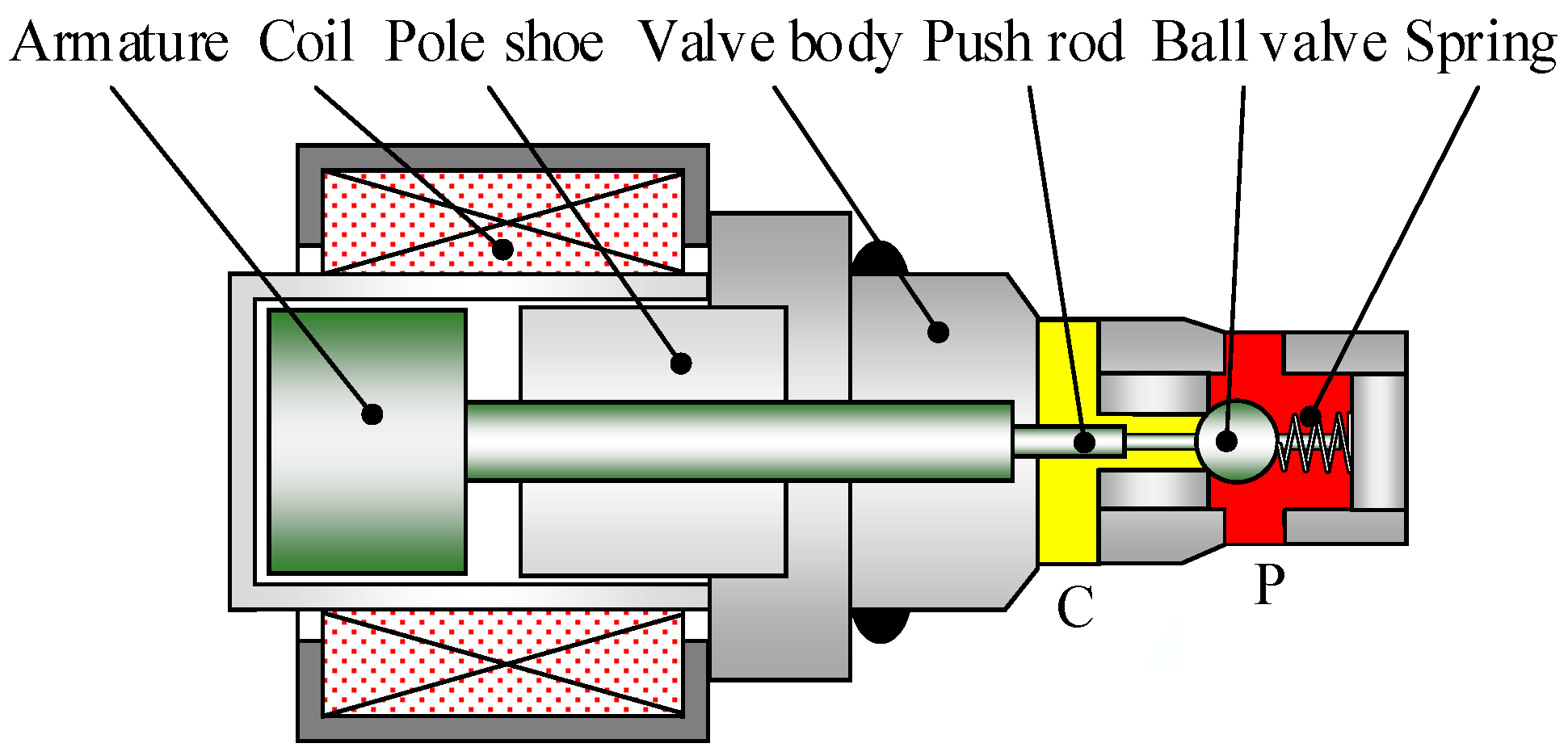
Figure 1. Structure diagram of the HSV driven by a solenoid.
As illustrated in Figure 1, the HSV consists mainly of an armature, a coil, a pole shoe, a push rod, a ball valve, a spring, and other components. It can be seen that the structure of the HSV is the same as that of the traditional solenoid valve. The differences are that the initial air gap of the HSV is smaller, and the number of coil turns needs to be optimized to meet the maximum electromagnetic force while effectively reducing the coil inductance. Secondly, the moving mass and maximum stroke of the ball valve are smaller than that of a solenoid valve. The working principle of the HSV is as follows: when the coil is de-energized in the initial condition, the electromagnetic force is 0, with the result that the ball valve maintains close contact with the valve seat under the action of the spring force and the hydraulic force. Conversely, when the coil is energized, the electromagnetic force starts to increase and is bigger than the combination of the spring force and hydraulic force, which causes the valve to gradually open.
1.2. Main Characteristics Analysis
The main performance indicators of the HSV include the dynamic characteristics, static flow characteristics, and heat transfer [1]. The relationships among these characteristics are as follow: the better the dynamic characteristics, the higher the output flow rate resolution of the HSV, and the better the static flow rate characteristics, the higher the linearity of the output flow rate.
1.2.1. Dynamic Characteristics
The dynamic characteristics of the HSV refer to the opening dynamic response and closing dynamic response of the ball valve, which are generally represented by the relationship between the valve’s displacement and the control signal, as illustrated in Figure 2. In Figure 2, the opening delay time tdon, opening moving time tmon, closing delay time tdoff, and closing moving time tmoff can be used to quantitatively characterize the opening and closing dynamic performance of the HSV.
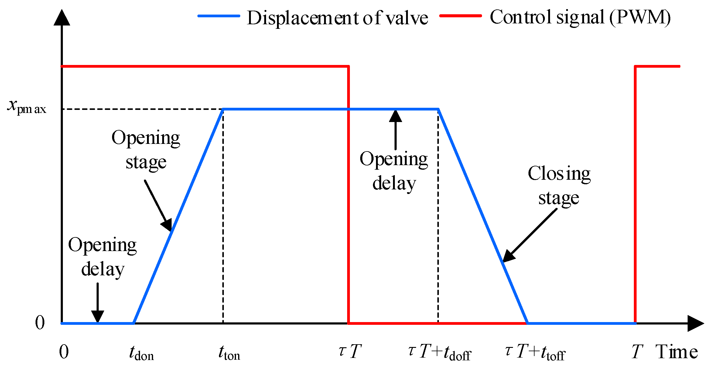
Figure 2. Schematic diagram of the movement of the valve.
Figure 2 shows that, there is a hysteresis in the displacement of the ball valve relative to the control signal, which is caused by a combination of the electrical hysteresis generated by the coil inductance and the inherent mechanical hysteresis [2]. Specifically, when the coil is energized, the electromagnetic force slowly rises because the coil inductance prevents the current from changing, and is less than the sum of hydraulic force, spring force, and friction force. Therefore, the opening delay time is determined by the electrical hysteresis and the mechanical hysteresis. When the coil is de-energized, the electromagnetic force slowly decreases due to the inductive hysteresis and the hysteresis of soft magnetic material. The ball valve maintains a fully open state, which corresponds to the closing delay time of the HSV.
1.2.2. Static Flow Characteristics
The static flow characteristics of the HSV consist of the relationship between the average output flow rate and the duty cycle of the PWM signal, as illustrated in Figure 3. The static flow characteristics of the HSV not only describe the maximum output flow rate capability but also the linearity degree between the output flow rate and the input control value.
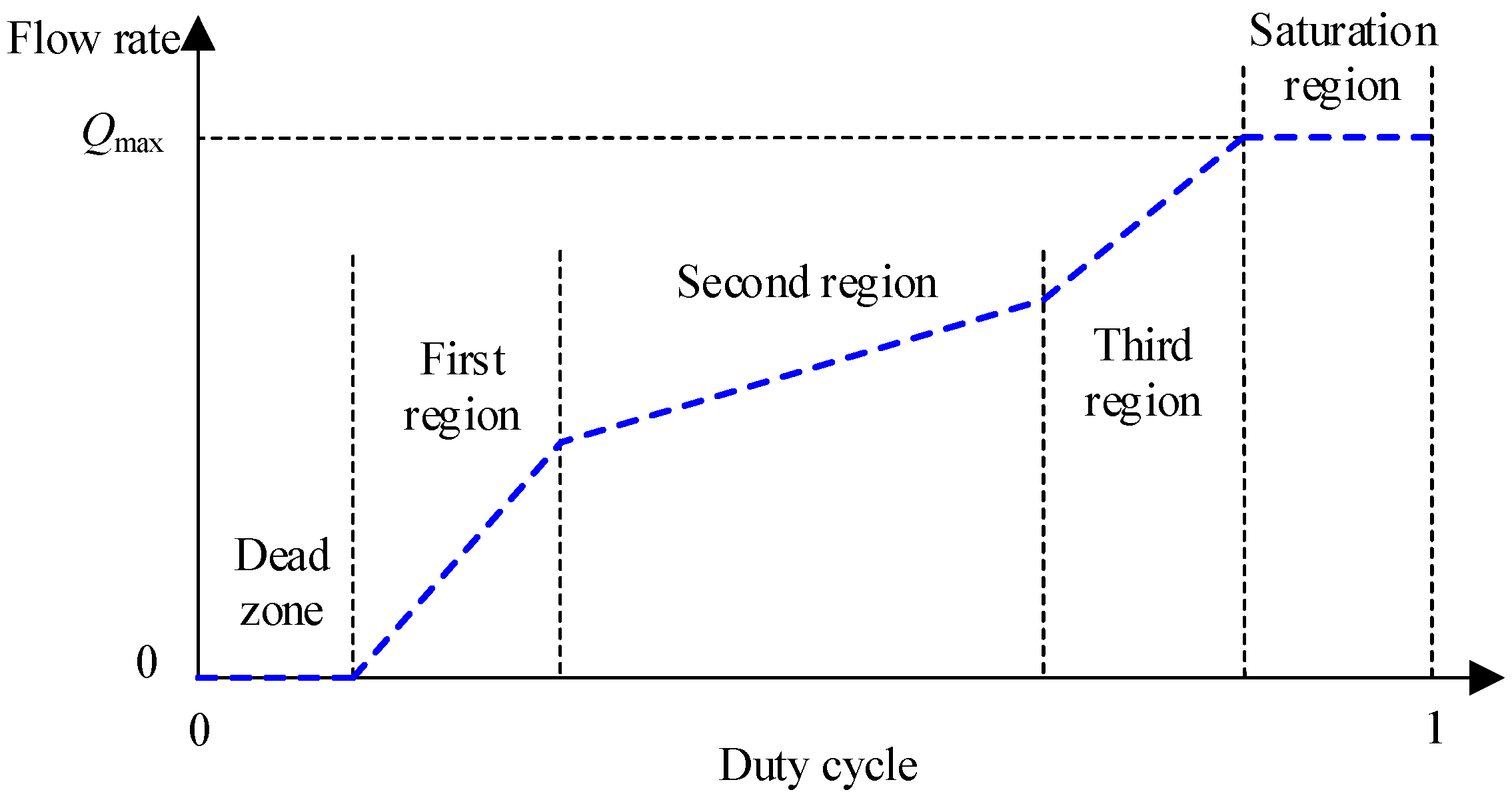
Figure 3. Static flow characteristics of an HSV.
As can be observed from Figure 3, the static flow curve of an HSV consists of five regions, including the dead zone, first region, second region, third region, and saturation, which correspond to the five states of the ball valve’s movement, such as unable to open, abnormal opening, normal opening and close, abnormal close and unable to close [3]. When the opening delay time and closing delay time both increase, the dead zone and saturation both expand, respectively, which results in a linearity decrease in the output flow rate. When the opening movement time and closing movement time increase, the first region and third region both extend, which also leads to a linearity reduction in the output flow rate.
Therefore, the prerequisite for improving the linearity of an HSV’s output flow rate is enhancing its dynamic performance, which means that the opening delay time, opening movement time, closing delay time, and closing movement time all need to be reduced. For a HSV driven by a solenoid, the dynamic response of the ball valve can be improved to some extent by optimizing the electro-mechanical converter [4][5], coil layout [6], and valve structure [7], but only at the new product development stage. Conversely, the control strategy is considered to be one of the most effective ways to improve the dynamic performance of a HSV during its service life.
2. Research Status of Control Strategy for Single HSV
The research on the control strategy of a single HSV has focused on improving dynamic performance and flow linearity, and reducing power consumption and vibration of the HSV. From the perspective of the control signal’s waveform, the control signals mainly include discrete voltage signals and pulse control signals. The discrete voltage signal combines several DC voltage signals with different amplitudes according to a certain logic, whereas the pulse control signal combines several pulse signals with different carrier frequencies.
2.1. Discrete Voltage Control Strategies
2.1.1. Single-Voltage Control
The working principle of the single-voltage control is defined as follows: when the controller detects the rising edge of the command signal, it outputs a DC voltage signal with a fixed amplitude to drive the HSV to open; and when the falling edge of the control signal is detected, the output voltage drops to 0. As illustrated in Figure 4, it can be seen that the waveform of the single-voltage control signal is the same as that of the conventional PWM signal.
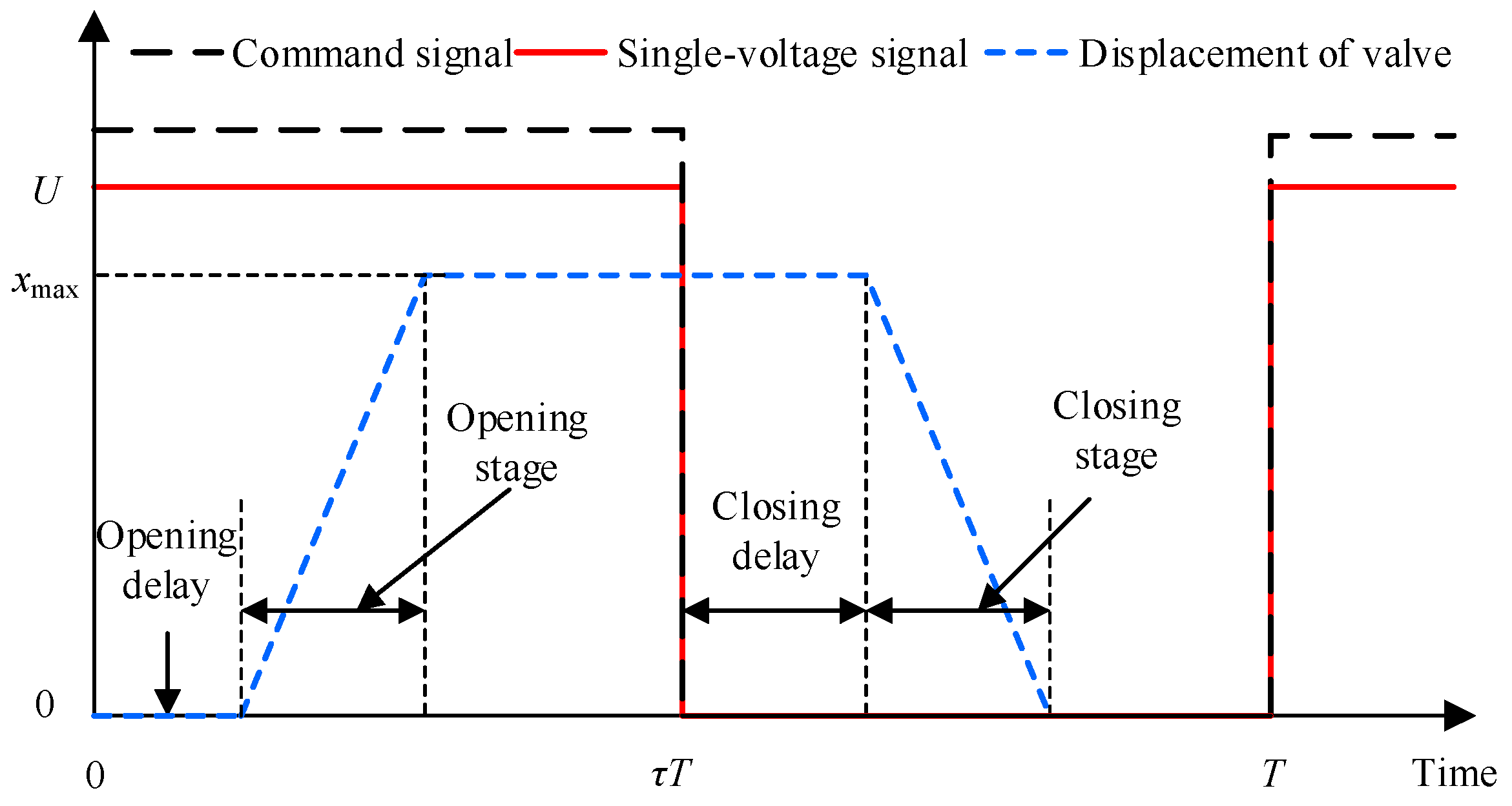
Figure 4. Diagram of single-voltage control signal.
Zhao et al. [8] conducted a large number of theoretical and experimental studies on the dynamic and static characteristics of HSVs under single-voltage control. It is clear that with an increase in the control signal’s frequency, both the dead zone and saturation of the output flow rate increase. When the control signal’s frequency is raised to 50 Hz, the effective duty cycle region is less than 0.3, and it has almost no flow rate regulation function. An HSV-controlled electro-hydraulic position servo system was proposed in Refs. [9][10] which uses a combination scheme of a directional valve and an HSV to achieve bi-directional closed-loop control of the cylinder. However, the maximum switching frequency of the HSV is only 50 Hz due to the use of a single-voltage control. Therefore, the position control accuracy of the HSV-controlled hydraulic position control system is less than that of a traditional position servo control system.
Existing research shows that the single-voltage control cannot meet the needs of the HSV in terms of high dynamic performance, low power consumption, vibration attenuation, and noise reduction. Moreover, a control system with a single voltage has poor robustness and cannot adapt to complex operating conditions.
2.1.2. Double-Voltage Control
The working principle of the double-voltage control is described as follows: when the controller detects the rising edge of the command signal, it outputs a high voltage signal to accelerate the opening of the valve; when the valve reaches the maximum position, the controller switches to low voltage mode (or negative voltage mode); and when the falling edge of the command signal is detected, the output voltage drops to 0, as illustrated in Figure 5.
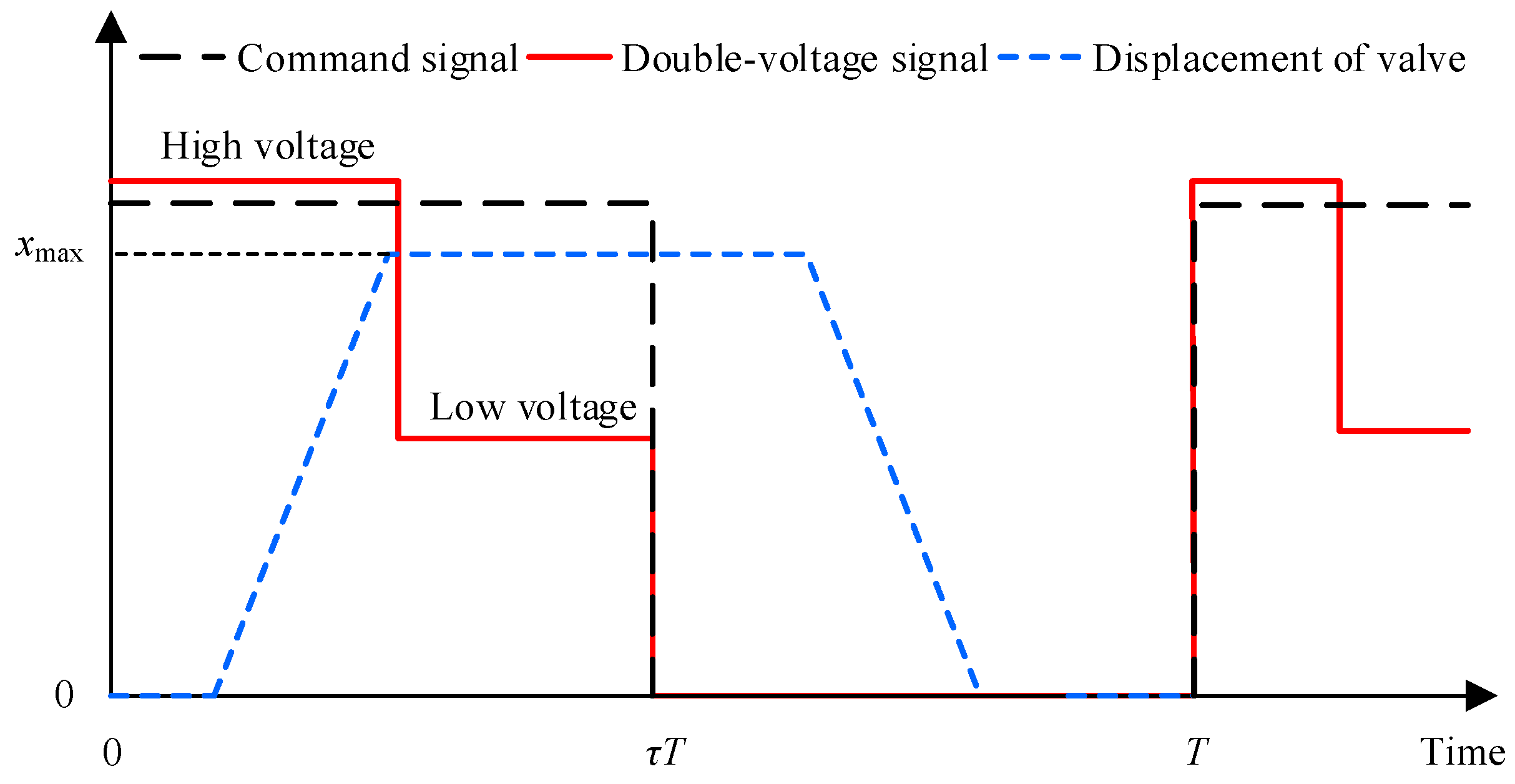
Figure 5. Diagram of double-voltage control signal.
Figure 5 shows that, compared with the single-voltage control, the double-voltage control can simultaneously improve dynamic performance and reduce power consumption by applying voltage signals with different amplitudes to the coil under different motion states of the valve. With respect to the double-voltage control research, Fulks [11] first proposed a boost-hold control strategy for a solenoid valve in 1989. In this research, a high voltage was used to drive the coil during the opening stage. When the ball valve reached the maximum opening position, the high voltage switched to a low voltage to maintain low power consumption. A novel poppet valve with multiple throttling edges piloted by a 2-position 3-way high-speed spool valve was designed by Winkler et al. [12]. In this research, the proposed valve was driven by the double-voltage control signal and the switching time of the proposed valve was only 2 ms. Linjama et al. [13] designed an AC Boost drive circuit for a parallel digital valve group. This circuit can output a double-voltage control signal based on capacitor charging and H-bridge driving technology. However, the maximum switching frequency of the digital valve was only 22 Hz due to the slow charging and discharging speed of the capacitor.
Su [14] studied the double-voltage control strategy of an HSV through simulation. First, a driving voltage with a duration of 1.6ms and an amplitude of 48 V is outputted to increase the opening speed of the ball valve in the opening stage. When the ball valve reaches the maximum opening position, a holding voltage with an amplitude of 14 V is output to reduce power loss, but the dynamic characteristics of the HSV vary significantly at different oil supply pressures. To address this problem, Su further applied an adaptive double-voltage control strategy, which dynamically regulates the driving voltage amplitude and holding voltage amplitude according to the supply pressure, which improved the robustness of the controller to a certain extent. The dynamic and static characteristics of HSVs under single-voltage control and double-voltage control determined through theory and experiments were compared in Ref. [15]. The results demonstrate that increasing the amplitude of the single-voltage signal can improve the opening speed of the valve but at the expense of the closing dynamic performance. Therefore, the double-voltage control decouples the opening and closing control processes of the valve, which achieves a good compromise between the opening speed, closing speed, and power consumption.
2.1.3. Three-Voltage Control
The working principle of the three-voltage control is defined as follows: when the controller detects the rising edge of the command signal, it outputs a high voltage signal to improve the opening speed of the valve; the controller switches to low voltage mode when the valve reaches the maximum opening position; and when the falling edge of the command signal is detected, the reverse voltage is outputted to accelerate the unloading speed of the coil current, which is beneficial to increasing the closing speed of the valve. The relationship between the control signal and the valve’s movement is illustrated in Figure 6. Compared with the single-voltage and double-voltage control, the innovation of three-voltage control is to apply reverse voltage to the coil during the closing stage of the valve and transform the spontaneous demagnetization state of the magnetic material into an active demagnetization state. This facilitates the rapid reduction of the electromagnetic force to increase the closing speed of the valve. In 2006, Lee [16] proposed a three-voltage control method to drive solenoid valves. In this research, a high voltage signal, a low voltage signal, and a reverse voltage signal were used during the opening stage, maximum opening stage, and closing stage of the valve, respectively. The measured results show that the switching delay time of the solenoid valve was reduced from 5 ms to 1.55 ms. Zhao et al. [17][18] designed a new structure of a high speed solenoid valve for common high-pressure rail fuel injection systems and provided a boost-hold-hold control strategy. The influences of the driving voltage and holding voltage on the dynamic characteristics and power consumption of the solenoid valve, respectively, were analyzed by numerical simulation. The results show that increasing the voltage amplitude at the moment of opening and reducing the voltage amplitude during the holding stage can significantly improve the dynamic performance and energy conversion efficiency of the HSV.
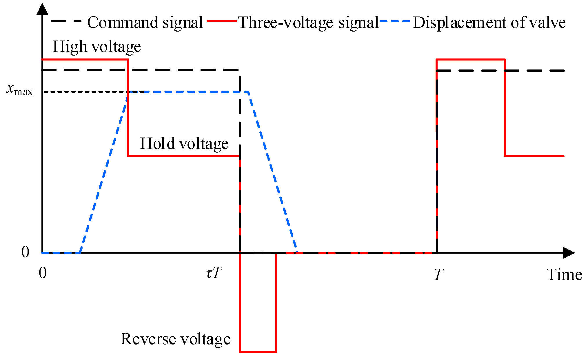
Figure 6. Diagram of three-voltage control signal.
To improve the robustness of three-voltage control strategy under different supply pressures, a three-voltage control strategy based on the coil current feedback was proposed in Ref. [19]. The working process is defined as follows: when the rising edge of the command signal is detected, the high voltage signal is outputted which leads to an increase of the coil current; when the coil current equals the critical opening current, a low voltage signal instead of the high voltage signal is used until the falling edge of the command signal is detected; and then a reverse voltage is outputted. The current begins to decrease until the current is less than the critical closing current and the output voltage is 0 at this time. In 2019, Liu et al. [20] proposed a multi-voltage control strategy that can adapt to different supply pressures. The results show that the opening and closing times of the valve were within 2.2 ms. A dual H-bridge conducting and continuous flow control strategy was designed by Sun et al. [21] which released the current from one coil to the other coil and the power supply at the instant of the valve’s closing. Comparisons of the experimental results show that, compared with the double-voltage control and the three- voltage control, the proposed control strategy presented the best performance. To maintain the dynamic characteristics of HSVs under different supply pressures, Zhong et al. [22] proposed a multi-voltage excitation strategy that adapts to the variation of the supply pressure. In this research, the strategy achieved automatic switching between multiple voltage sources by calculating the critical on/off current in real-time. However, in practical applications, the accuracy needs to be further improved due to several nonlinear factors, such as magnetic saturation, leakage, and hysteresis.
2.1.4. Four-Voltage Control
The working principle of the four-voltage control is described as follows: the controller outputs a preload voltage signal when the system begins to run, and at this time, the coil current begins to increase but not equal to the critical opening current; when the rising edge of the command signal is detected, a high voltage signal is used instead of the preload voltage signal to accelerate the valve’s opening; and when the current reaches the critical opening current, the controller starts to output the holding voltage signal. The reverse voltage is used to increase the closing speed of the valve when the falling edge of the command signal is detected, as illustrated in Figure 7.
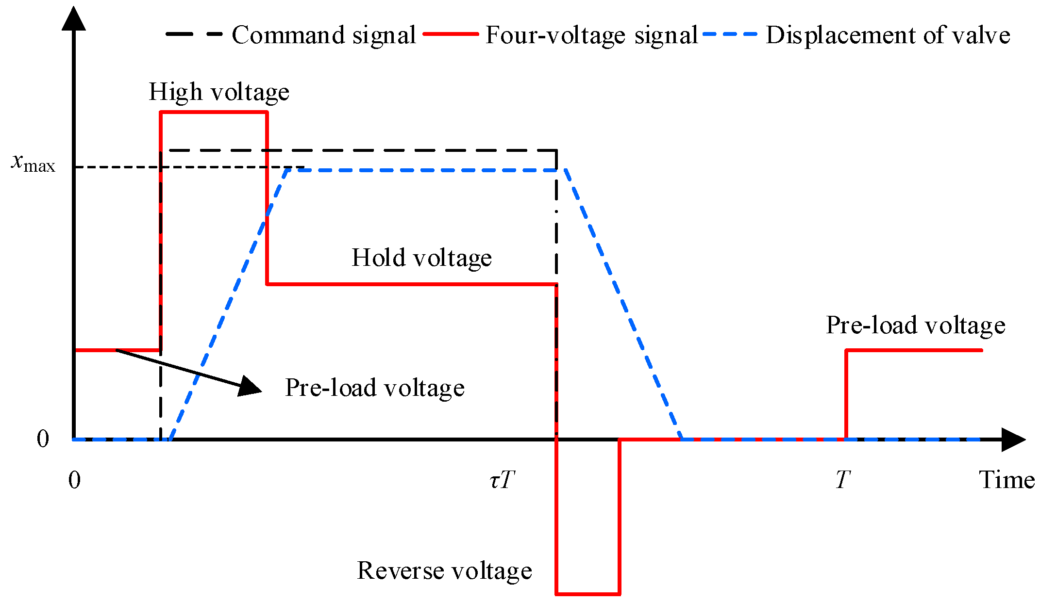
Figure 7. Diagram of four-voltage control signal.
Figure 7 shows that, compared with the single-voltage, double-voltage, and three- voltage control, the main improvement of the four-voltage control is to increase the initial current by exciting a low voltage to the coil before the valve opens. In Refs. [23][24], a pre-existing voltage control algorithm which adapts to the different supply pressures was proposed, and the corresponding flow chart is presented in Figure 8. In this research, a low voltage was preloaded to the coil before the valve opened and the opening dynamic performance of the valve was improved by increasing the initial current. The results indicate that compared with the double-voltage control, the opening lag time of the valve was reduced by 66.7% under the preloaded voltage control. Liu et al. [25] provided a hybrid voltage control strategy to improve the dynamic response speed of a solenoid cartridge valve. In this research, the output signal of the control strategy consisted of a preload voltage, a high voltage, a hold voltage, and a reverse voltage signal. The measured results demonstrate that compared with the single-voltage control strategy, the opening time of the solenoid cartridge valve was reduced from 29.5 ms to 7.6 ms.
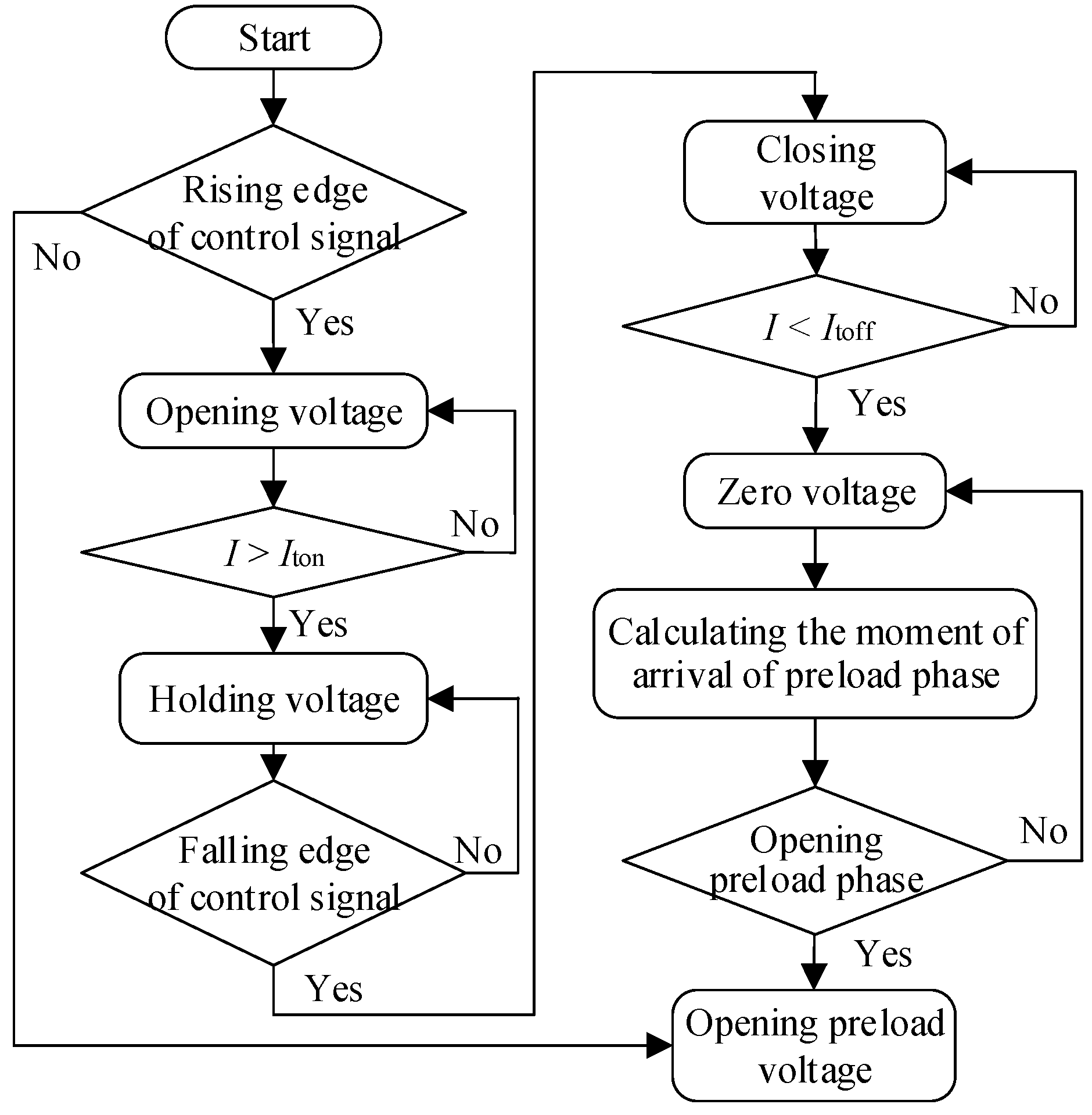
Figure 8. Flow chart of pre-existing multi-voltage control.
2.1.5. Multi-Voltage Control Circuit
The above subsections mainly introduce the control strategies of HSVs but ignore the implementation of the control signals. The main functions of the control circuit of an HSV can be summarized as follows: real-time acquisition of key parameters (pressure, flow rate, and temperature), which are used as the basis for the calculation of the control law; a discrete voltage control signal is enabled based on the command signal; and the power amplifier circuit is further used to amplify the control signal and output a high-power drive signal that can directly drive the HSV.
In terms of research on the control circuits of HSVs, many scientific research institutions were involved in early research and have produced many informative works. A high-frequency AC BOOST circuit is proposed by Lassi [26], which is different from the traditional dual-field-effect-tube H-bridge drive circuit. This circuit only needs one field-effect tube, but the measured data shows that the charging time of the capacitor was close to 45 ms. Tapio [27] designed a miniature high-flow rate digital valve system consisting of 32 digital valves. A multi-voltage control circuit based on the Atmega 128 microcontroller was also developed. As illustrated in Figure 9a, the driver consists of a microprocessor, a BOOST circuit, and a power supply. The microprocessor decodes the bus signal into digital control signals for each valve, and the control signals are amplified by the BOOST circuit to directly drive multiple digital valves. Wu et al. [28] developed a dedicated controller based on the DSP TMS28335, as shown in Figure 9b. The controller hardware consists of a reference board, a control board, and a driver board. The driver board consists of a P-channel increasing MOSFET, a TLP optocoupler, and two voltage power suppliers, whose main function is to transform the command signal into a double-stage voltage drive signal. However, the controller is large in size and needs further optimization. To improve the linear operating region of the output flow rate of a variable spray solenoid valve, Shen et al. [29] designed a flow rate controller consisting of a microcontroller, PWM signal generator and driver circuit. The controller receives the command signal from the host computer via the RS485 bus and combines the BOOST circuit with the conventional circuit to output a double-voltage signal.
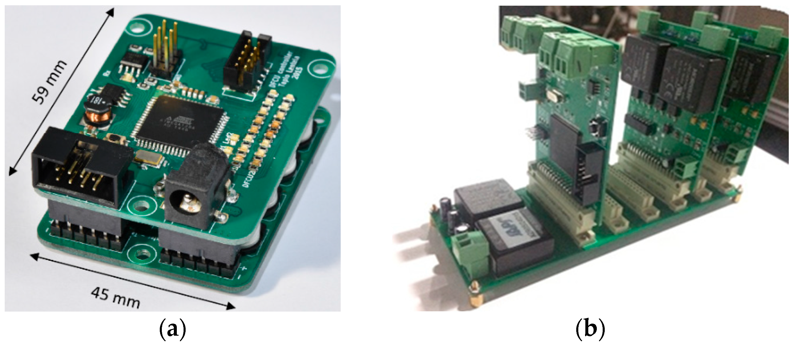
Figure 9. Multi-voltage control circuits: (a) control circuit based on the Atmega 128 microcontroller; and (b) control circuit based on the DSP TMS28335.
In 2021, to solve the impact of the current pulse on the power supply in the double-voltage driving circuit, Wang et al. [30] designed a current suppression circuit based on a super capacitor. The measured results show that the current pulse reduction reached 71%. Patent [31] proposed a multi-voltage drive circuit for an HSV, which consists of a power supply module, a signal processing module, and a driver module. The power supply module is used to provide three level voltages (high, low and negative). The signal processing module is used to output the control signal. The driver module mainly consists of a photocoupling amplifier and a MOS tube driver element. The photocoupling amplifier is used to isolate and amplify the driver signal. The MOS tube driver element is used to regulate the driver circuit, and finally outputs a three-voltage signal to control the operation of the HSV.
From the development history of multi-voltage control circuits for HSVs, it can be seen that the functions of multi-voltage control circuits are increasingly diversified and include signal acquisition and isolation, voltage amplification, bus transmission, and closed-loop control. However, the structure size, heat generation, and reliability of the control circuits all still need to be improved to meet the actual requirements of a large number of applications.
2.2. Pulse Control Strategies
In contrast to the discrete voltage control signal, the pulse control signal is composed of pulse signals with different carrier frequencies according to a certain logic. The pulse control signal is amplified by a power amplifier circuit to control the output flow rate of the HSV.
2.2.1. Compound PWM Control Strategy
The working principle of the compound PWM control strategy is defined as follows: when the rising edge of the command signal is detected, a PWM signal with a large duty cycle is used to accelerate the valve’s opening; when the valve moves to the maximum opening position, a high-frequency PWM signal with a small duty cycle is used to reduce thermal power consumption; and when the falling edge of the command signal is detected, a reverse PWM signal is outputted to accelerate the unloading of the coil current. The compound PWM control signal is shown in Figure 10.
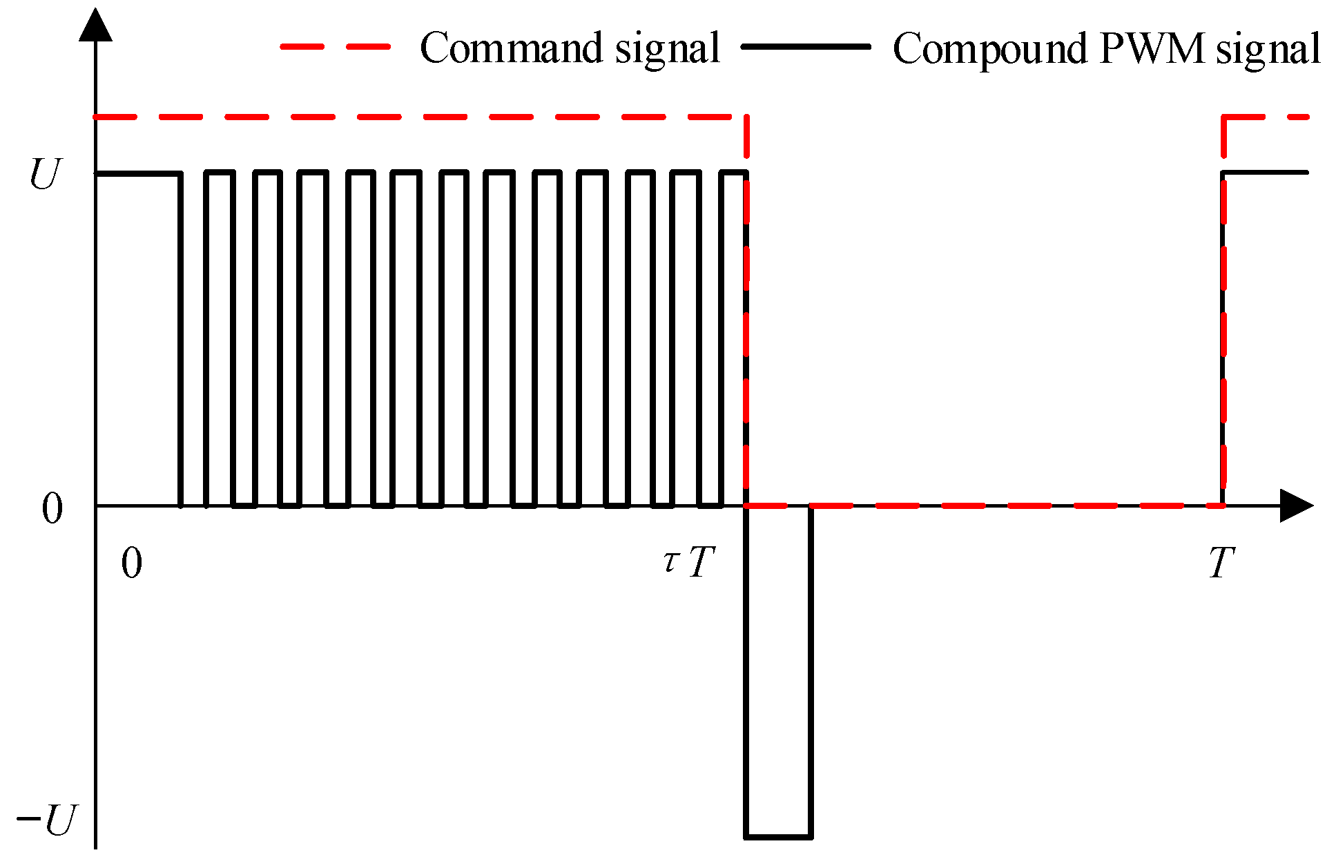
Figure 10. Schematic diagram of compound PWM control signal.
Figure 10 shows that, compared with the discrete voltage control, the compound PWM control is composed of multiple PWM signals with different carrier frequencies. The development of the compound PWM control can be traced back to 15 years ago. To improve the dynamic performance of the solenoid valve and the effective region of the duty cycle, a compound PWM control strategy with the same effect as three-voltage control was proposed by Taghizadeh et al. [32]. The quantified relationship between the duty cycle of the compound PWM signal and the average output displacement of the valve at different frequencies was investigated theoretically, and it was concluded that the effective duty cycle region remains 60% at 80 Hz.
Gao et al. [33] proposed a compound PWM control signal which consists of a reference PWM, an excitation PWM, a high-frequency PWM, and a reverse PWM signal. The influences of the duty cycle of each functional PWM signal on the dynamic characteristics of the HSV are analyzed through simulation, and the design criterion of the duty cycle is given on this basis. Simulation results show that the closing time of the HSV is reduced by 62.5%, compared to the conventional PWM control. To drive the threaded cartridge solenoid valve, a compound PWM control signal was proposed in Ref. [34]. In this research, the effect of the action time of each functional PWM signal on the motion characteristics of the solenoid valve is studied by AMESim. The results show that the proposed control strategy is basically consistent with three voltage control. In addition, the opening time of the solenoid valve is reduced from 30 ms to 13 ms and the closing time is reduced from 139 ms to 14 ms.
2.2.2. Adaptive PWM Control
The control principle of the adaptive PWM is described as: the duty cycle of each function PWM signal is designed to achieve dynamic matching with oil supply pressure based on the oil supply pressure and current feedback; and finally, the optimal performance of the HSV is always maintained under different oil supply pressures. For example, Zhong et al. [35][36] proposed a self-correcting PWM control strategy based on current feedback to reduce the influence of oil supply pressure on the dynamic characteristics of the HSV. The design criterion of the duty cycle of the PWM signal during the opening/closing stages of the HSV mainly depends on the critical opening and closing currents. The results show that when the oil supply pressure varied in the range of 4 MPa to 20 MPa, the variation in the dynamic time was only 0.3 ms. An adaptive compound PWM control strategy was designed by Gao et al. [37], as illustrated in Figure 11. In this research, a state observer is proposed to monitor the HSV’s displacement in real time, and the feedback values of oil supply pressure and current were combined to control the duration of the drive voltage signal. The results show that the pressure delay time was reduced from 13 ms to 2 ms and the temperature rise of the coil shell was reduced by 61.5%. In the end, this strategy can better maintain the dynamic performance of HSVs under different oil supply pressures.
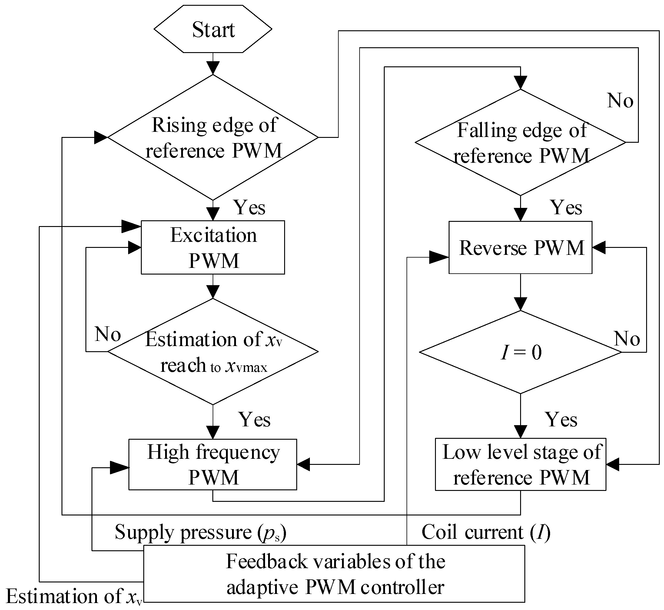
Figure 11. Flow chart of adaptive PWM control.
2.2.3. Intelligent PWM Control
To improve the adaptability of HSVs under complex operating conditions, the self-adjustment capability of the dynamic characteristics of the HSV is crucial. To address this issue, an advanced pulse width modulation control strategy was proposed in Ref. [38] in which the opening initial current and closing initial current are controlled by the duty cycles of the pre-existing PWM and holding PWM signals during the opening stage and maximum position holding stage; thereby, the intelligent regulation of the opening and closing dynamic performance is realized. The results show that the dynamic adjustment ranges of the opening delay time, total opening time, closing delay time, and total closing time of the HSV after adopting the intelligent PWM control algorithm were widened to 0.2–18.3 ms, 2.1–32.1 ms, 0.1–6.8 ms, and 1.9–12.9 ms, respectively. Therefore, this research can further promote the application of HSVs in different fields.
2.2.4. Soft-Landing PWM
During the fast opening and closing stages of the HSV, high-speed collision inevitably occurs, which leads to strong vibration and noise. Therefore, it is necessary to study how to achieve a soft-landing without changing the structural parameters.
According to the existing literature, the optimization strategy of the control signal is one of the most effective approaches to realizing a soft-landing of the HSV. Gao [39] conducted much simulation work and found that both the opening dynamic performance and the soft-landing performance of the HSV can be maintained by adding a negative voltage to the coil during the opening stage of the HSV. Compared with the conventional PWM control, the experimental results show that the average acceleration and noise were reduced by 65.7% and 12%, respectively. An adaptive soft-landing PWM control strategy for the HSVs driven by solenoid, was invented and is subject to a patent [40]. The design is presented in Figure 12. In contrast to the compound PWM control signal, the proposed control signal adds a reverse voltage pulse signal to reduce the electromagnetic force during the opening stage of the HSV. Further, the design criterion of the start time and end time of the reverse voltage signal were obtained through simulation. The simulation results show that, compared with the compound PWM control, the impact velocity of the valve was reduced by at least 31% with the soft-landing PWM control strategy, whereas the total opening time of the HSV was increased by only 5%.
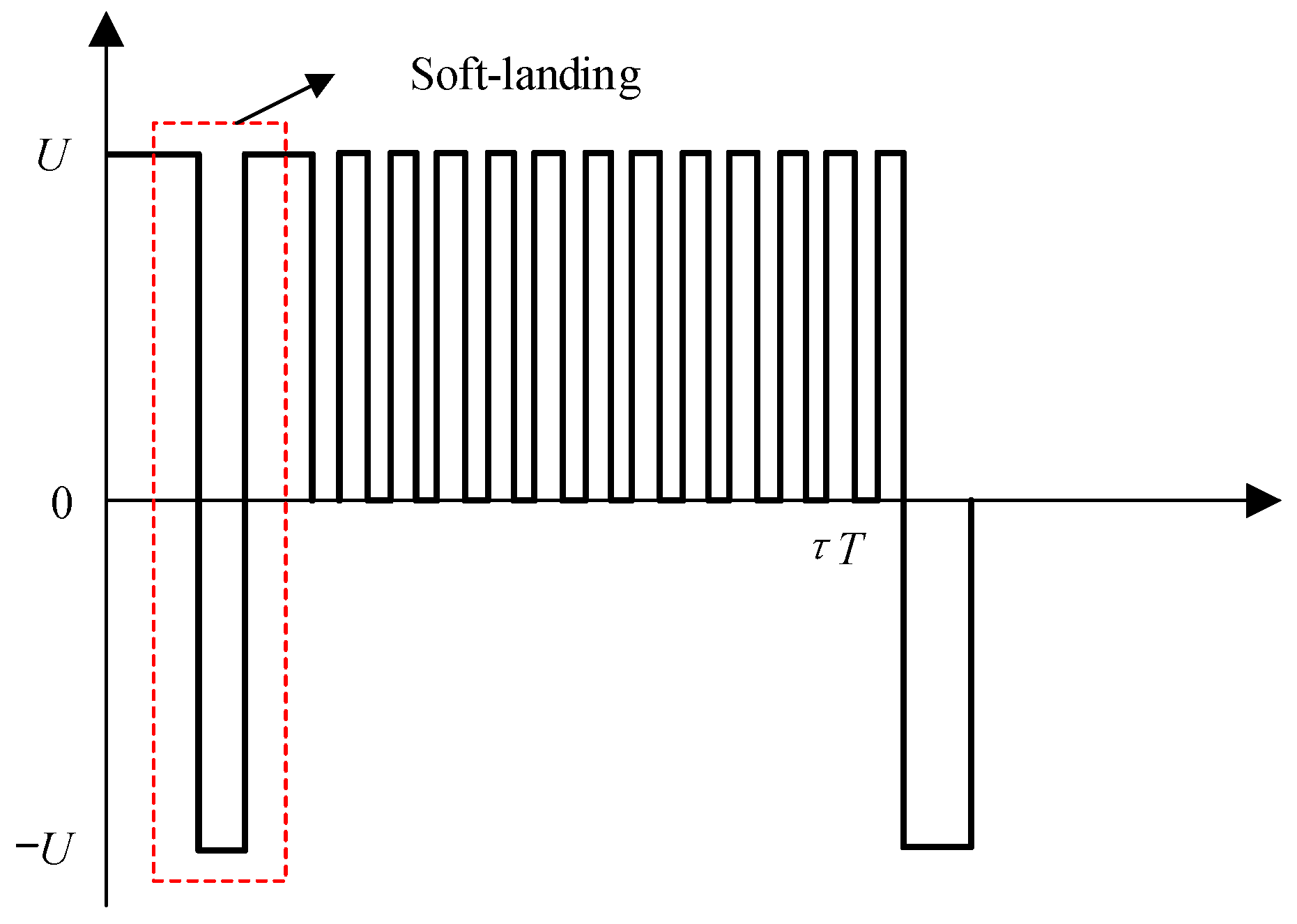
Figure 12. Schematic diagram of soft-landing PWM control signal.
A soft-landing PWM control method for HSVs driven by piezoelectric energy was proposed in Reference [41]. In this patented design, the power function signals are used as the control signals of the piezoelectric stack during the opening and closing stages of the HSV, and the motion trajectory of the HSV can be controlled by adjusting the exponential value of the power function. The results show that, compared with a conventional PWM control, the vibration acceleration of the valve body can be reduced by 70.8% with this soft-landing strategy. The opening time and closing time were only delayed by 0.6 ms.
2.2.5. Other Pulse Signal Modulation Strategy
Under the conventional PWM control strategy, a smaller duty cycle means a shorter excitation time of the driving voltage. Due to the influence of electrical and mechanical hysteresis, the electromagnetic force increases slowly and is less than the hydraulic force, with the result that the valve cannot open properly, leading to a dead zone in the flow rate. A large duty cycle means the power-off time is short and the electromagnetic force drops slowly and is greater than the hydraulic force, with the result that the ball valve cannot normally close, leading to a saturation of the flow rate. To address these problems, a control strategy based on the PWM and PFM signals was provided by Liu et al. [42]. In this research, the dynamic adjustment of the effective duty cycle region is achieved by reducing the frequency of the pulse signal under the conditions of the small duty cycle and large duty cycle. Further, Gao et al. [43] improved the control accuracy of the HSV-controlled hydraulic position system by effectively combining fuzzy control and PWM-PFM control algorithms.
2.3. Comparative Analysis of Different Control Strategies for a Single HSV
By summarizing the research status of control strategies for a single HSV, the comprehensive performances of different control strategies are compared in detail from the perspectives of opening dynamic performance, closing dynamic performance, energy saving, vibration and noise reduction, and robustness. In Table 1, the greater the number of asterisks “*”, the better the corresponding performance.
Table 1. Performance comparisons of the control strategies for a single HSV.
| Control Strategy | Opening Dynamic Performance | Closing Dynamic Performance | Energy Efficient | Vibration and Noise Reduction | Robustness |
|---|---|---|---|---|---|
| Single-voltage control | **** | * | * | * | * |
| Double-voltage control | **** | ** | **** | * | ** |
| Adaptive single-voltage control | **** | *** | ***** | * | *** |
| Three-voltage control | **** | **** | *** | ** | *** |
| Adaptive three-voltage control | **** | ***** | **** | *** | **** |
| Four-voltage control | ***** | **** | ** | *** | *** |
| Adaptive four-voltage control | ***** | ***** | *** | *** | **** |
| Compound PWM control | **** | **** | *** | * | *** |
| Adaptive PWM control | **** | ***** | **** | *** | **** |
| Intelligent PWM control | ***** | ***** | **** | *** | **** |
| Soft-landing PWM control | *** | **** | *** | ***** | *** |
Asterisks denots the superiority degree of the performance. The greater the number of asterisks “*”, the better the corresponding performance.
The opening dynamic performances of the four-voltage control, adaptive four-voltage control and intelligent PWM control are optimal since the driving voltage is already used before the rising edge of the command signal is detected. In contrast, the soft-landing PWM control adds a reverse voltage signal during the opening stage of the HSV, and the decrease in the electromagnetic force causes the slower movement of the HSV, so the opening dynamic performance is the worst.
The closing dynamic performances of the adaptive three-voltage control, adaptive four-voltage control, adaptive PWM control and intelligent PWM control strategies are optimal since a reverse voltage signal is dynamically used during the closing stage of the HSV. The power consumption of the adaptive double-voltage control is the lowest since it only applies voltage during the opening stage and maximum opening holding stage, and the voltage amplitude changes with the variation in the oil supply pressure, whereas the single-voltage control strategy has the largest power consumption due to the use of high voltage to excite the electromagnetic coil. The vibration and noise reduction performance of the soft-landing PWM control is optimal since it optimizes the electromagnetic force by increasing a reverse voltage signal during the opening stage of the HSV, which reduces the landing speed. In terms of robustness, the adaptive three-voltage control, adaptive four-voltage control, adaptive PWM and intelligent PWM control all have the strongest robustness because the control laws of these control algorithms dynamically match with the oil supply pressure, and the sensitivity to variation in the oil pressure is the lowest.
3. Research Status of Control Strategy for Parallel HSVs
To realize the flow rate regulation of the parallel HSVs, the opening and closing states of each valve need to be controlled. At present, the control signals such as PWM coding, PFM coding, PNM coding, and PCM coding are often used. Due to the different functions and applicability of each coded signal, the control strategies of the existing parallel HSV can be divided into two categories, namely, single code control and hybrid code control. The single code control regulates the opening and closing states of the parallel valves by using a coded signal. The hybrid code control regulates the output flow rate of the parallel valves by combining at least two coded digital signals.
3.1. Single Coding Control Strategy
3.1.1. PWM Control
PWM control strategy can not only control a single HSV but also parallel HSVs. The control concept of parallel HSVs is basically the same as that of a single HSV, which is that the PWM signals with different duty cycles are used to control each valve. For example, Li et al. [44] used multiple on/off valves connected in parallel to control the hydraulic cylinder. A high-frequency PWM signal was used to control different on/off valves to achieve different levels of flow rate regulation, allowing the speed control of the hydraulic cylinder. However, the control strategy caused several problems, such as pressure fluctuation and life reduction of the valve. A proportional flow control valve piloted by parallel HSVs, which uses PWM signals to control the pilot HSV, was proposed by Xiong et al. [45]. The results show that the average output flow rate of the main valve was approximately proportional to the input duty cycle. In Refs. [46][47], a negative pressure servo system, which is based on parallel HSVs and consists of a charging unit and a discharging unit, was designed. To eliminate the influences of operating points on the characteristics of the charging unit and discharging unit, an asymmetric compensation control algorithm of the PWM signal was proposed to achieve high-accuracy tracking at different frequencies and different pressures. The experimental results indicate that the proposed control strategy has the advantages of high control accuracy and strong robustness.
In conclusion, the advantage of parallel HSVs using PWM control is the high accuracy of flow rate regulation, but this approach simultaneously leads to some problems, such as pressure shocks, short service life, and vibration noise.
3.1.2. PFM Control
The frequency of the pulse frequency modulation (PFM) signal varies with the input control quantity. The PFM control strategy has the advantages of high control accuracy, high conversion efficiency, and fast response. However, the PFM control suffers from the same problems such as pressure fluctuation, vibration noise, and short service life because the on/off valve always works in a high-frequency switching state.
According to the available literature, scholars have been applying the PFM coding technique to on/off valve control systems since 2012. Under the condition of constant pulse width, the control precision of the approximate proportional/servo can be obtained by increasing the frequency of the pulse signal [48][49]. For example, a prototype of an equal coded parallel digital valve unit consisting of 16 miniature digital valves was designed and assembled by Paloniitty et al. [50] at the Tampere University of Technology in 2015. To solve the problem of poor resolution of the digital valve units’ output flow, an improved PFM coding control strategy was proposed. The pulse signal was cyclically distributed to each digital valve, and the control accuracy and the service life of the digital valve were effectively balanced.
3.1.3. PNM Control
Pulse number modulation (PNM) is the most common control method for equal coded parallel on/off valve groups in which the number of on/off valves is controlled to achieve the superposition of the required flow rate. Therefore, the value of the output flow rate is consistent with the number of the on/off valves, and the flow rate resolution depends on the output flow rate of the minimum valve. A segmentation control idea to improve the control accuracy of the parallel on/off valves-controlled position servo system was presented by Gao and Zhu [51]. The PNM coding and the differential PWM control strategy were used under high-speed and low-speed working conditions, respectively. Further, to improve the service life of the on/off valves, a cycle buffering strategy was proposed to achieve a uniform distribution of the PNM-coded signals, as shown in Figure 13. The experimental results show that the average and minimum positioning errors were 0.528 mm and 0.221 mm, respectively, and the total number of switching times of the on/off valves was only 39.
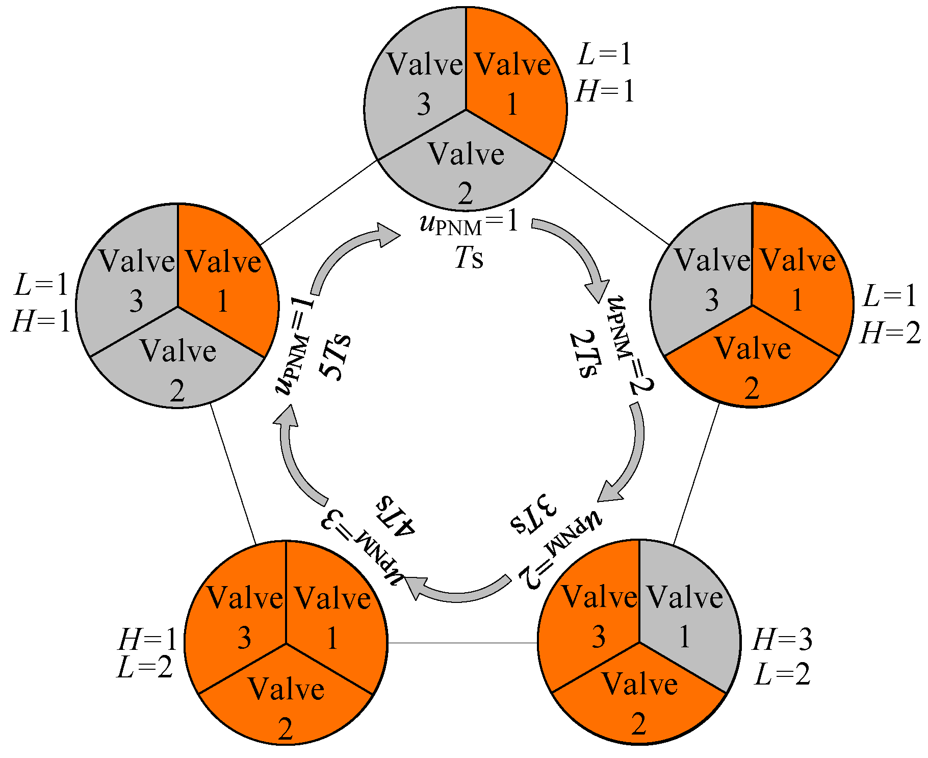
Figure 13. Optimization strategy of PNM coding signal.
Simic and Herakovic [52] proposed an independent metering control system based on a parallel digital piezoelectric valve group. The digital valve was driven by three piezoelectric stacks with the same axial length in series, and the PNM-coded signal was used to control the operating state of each piezoelectric stack. The research results show that, compared with the traditional solenoid valve-controlled system, the power consumption of the system could be reduced by six times in the steady state. In addition, the response speed and energy-saving efficiency were both significantly improved.
It can be seen that the on/off valve does not require high-frequency switching under PNM coding control and has the advantages of small pressure fluctuation, low vibration noise, and long service life. In addition, since the flow rates of each valve are the same, the output flow rate has strong redundancy and high reliability. However, the PNM coding strategy is essentially considered to be “step regulation”, and the control accuracy depends on the flow rate of the minimum valve. Therefore, the PNM coding control strategy is often used in combination with other coded control strategies.
3.1.4. PCM Control
Pulse code modulation (PCM) is a common control method for binary-coded parallel HSVs. Since the flow rate of each valve is arranged in binary, the combinations of the opening/closing states of the valve group reach 2N. The resolution of the output flow rate is 1/2N (N is the number of valves), and the control accuracy increases exponentially with the number of valves.
Tampere University of Technology in Finland is a pioneer in the research into the PCM control of parallel on/off valves. For example, in 2005, to improve the position control accuracy of a parallel HSVs-controlled cylinder, Linjama and Vilenius [53] proposed a PCM control strategy with a cost function. The results show that the position error was 1mm when tracking the peak speed of 200 mm/s. Wu et al. [54] used four on/off valve groups to form an independent metering control system to accomplish the position tracking of the hydraulic cylinder. In this research, a fixed throttle port was connected in series behind each on/off valve, and the flow area of the fixed throttle port was arranged in binary. Inspired by the working principle of the dual nozzle flapper, a structure of the fuel metering valve based on the binary-coded HSVs was proposed in Ref. [55]. To improve the position tracking accuracy of the fuel metering valve, a position control strategy consisting of velocity feedforward, position feedback, and model-based PCM coding was proposed. The results show that the average tracking error was reduced by 78%.
3.2. Compound Coding Control Strategy
3.2.1. PCM+PWM
According to Section 2.1, for a single coding control strategy, the control accuracy of the PWM and PFM is the best but at the expense of the number of switching times of the valves. In addition, the service life of the valve under PNM and PCM control is the longest, but the control accuracy of the on/off valve needs to be improved. Therefore, how to effectively combine different types of coding control strategies to achieve complementary advantages is a research hotspot for scholars.
Huova and Plockinger [56] adopted PCM and PWM coding signals to control the binary-coded on/off valve group. In this research, accurate control of the output flow rate was achieved by adjusting the duty cycle difference between the two PWM signals. However, the optimal selection of the digital valves driven by PWM signals was neglected, so the service life of the valves was seriously affected. Moreover, due to the constraints of the dynamic response of the valves, the control accuracy needs to be further improved under the condition of a small duty cycle. A control valve group was designed by Kang et al. [57] which consisted of a binary-coded digital valve group and a digital valve driven by a PWM signal. The digital valve group was used to provide the reference flow rate, and then PWM control was used to achieve fine flow rate regulation. The research results demonstrated its successful use in the flow rate regulation system of the FL-12 wind tunnel’s air supply, and the maximum absolute error was only 2.7 g/s. Jiang et al. [58] proposed a digital valve group driven by a combination of PWM and PCM control signals. As depicted in Figure 14, the digital valve group consisted of four binary-coded digital valves and one small flow rate digital valve. Further, a time lag control strategy of the digital valve group was proposed based on the function of the flow rate impact. The results show that, compared with the PCM coding control, the proposed control strategy had better control performance and also a certain suppression effect on the flow rate impact during switching.
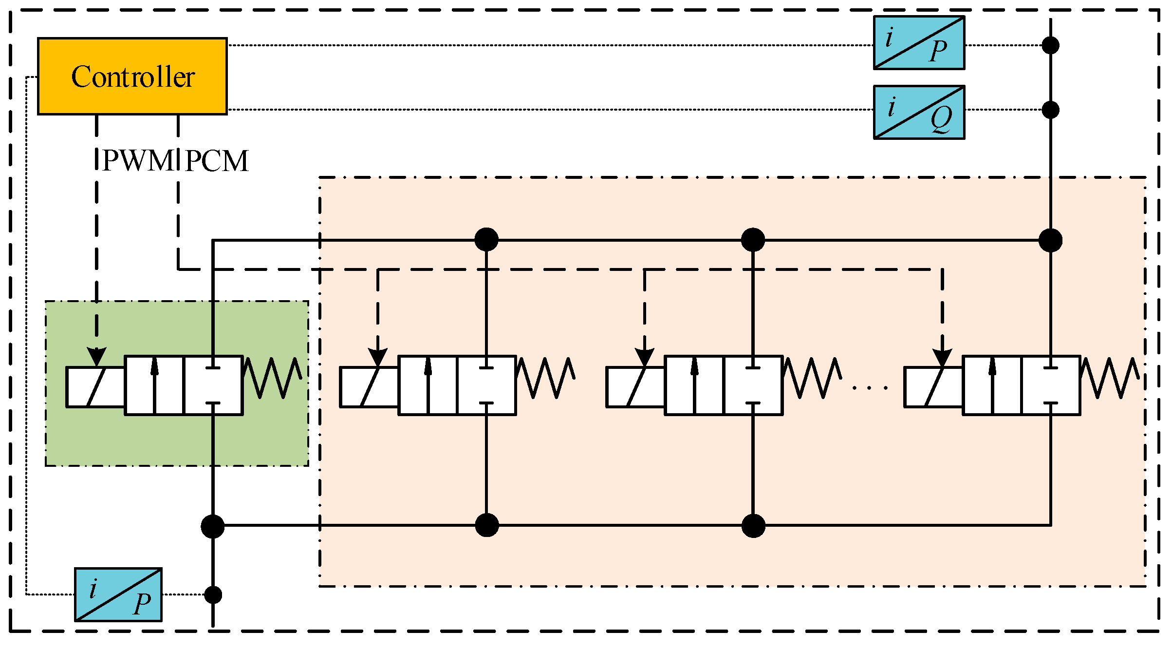
Figure 14. Digital valve group driven by PWM and PCM.
3.2.2. PCM+Analog
Compared with the control scheme of the PCM+PWM combination, the continuous fluid control technology integrated into the control scheme of the PCM+analog combination is used to further improve control accuracy. However, the system is no longer a digital hydraulic system in the true sense. To address this situation of low transmission efficiency in a high-power hydraulic valve control system, Yao et al. [59][60] proposed a D+A multi-pump source structure. The PCM-coded signals were used to control the working states of the fixed displacement pump group, and the high-precision compensation of the flow rate was realized by the variable pump. The experimental results show that the position tracking accuracy reached ±0.1 mm, and the efficiency and control accuracy of the system were significantly improved. To address the demand for the improvement of regulating the precise air supply flow in wind tunnels and the shortcomings of existing analog control valves, a digital flow regulation device based on a combination of a binary-coded valve group and a needle valve was designed in Ref. [61]. To output a large flow rate, the PCM-coded signal was used to control the switching states of the on/off valve group. Further, the micro-flow control was achieved by adjusting the opening of the needle valve. The results show that the flow control accuracy reached ±3g/s.
3.2.3. PNM+PWM
Since the control accuracy of the PNM coding only depends on the number and output flow rate of the on/off valve, the demand for high-precision tracking cannot be fulfilled. Currently, the PWM control strategy is mostly used to compensate for the defect of low control precision of the PNM control strategy. For digital valve-controlled position servo systems, Paloniitty and Linjama [62] proposed a novel control strategy that integrated PNM coding, multi-valve PWM, buffer optimization, and PFM coding algorithms. The multi-valve PWM algorithm was used to reduce the total number of switching times of the digital valves. The buffer optimization strategy was used to improve the uniformity of the switching times among all valves, and the PFM coding algorithm was used to improve the flow rate linearity by reducing the signal frequency under a small duty cycle. To address the problem of low positioning accuracy in the digital valve-controlled position system, a position control strategy combining PNM coding and differential PWM was proposed by Gao et al. [63]. In this research, a cost function with adaptive weights was proposed to achieve a better balance between the total number of switching times and the control accuracy of the digital valves. Further, to improve the uniformity of switching times of the digital valves, a circular buffer and a new circular switching method were proposed. The results show that the average and minimum positioning errors were 10 μm and 1 μm, respectively. Moreover, the uniformity of switching times among all digital valves was significantly improved.
3.2.4. Other Types
In recent years, to improve the control accuracy and service life of digital hydraulic systems, besides the coding control algorithms described above, various advanced control algorithms have been successively proposed, including bang-bang, phase control, multi-mode control, time-interlaced modulation, and sliding mode control. For example, in 2010, Long et al. [64] compared the control performance of a 2-position 3-way HSV and 2-position 2-way HSV by theory and experiment. The performances of some control algorithms were also investigated. The results show that the control accuracy and the switching times of the on/off valve could be effectively balanced under the pulse control strategy. Hodgson et al. [65] used four HSVs to form a full bridge to control the cylinder’s position and proposed a new seven-mode sliding mode control algorithm. The results show that, compared with the three-mode control, both the position error and switching times could be reduced under the seven-mode sliding mode strategy. Four on/off valve groups were used in Ref. [66] to form an independent metering control structure to control the position of the hydraulic cylinder. In contrast to the conventional PWM control and PFM control, a smaller number of pulse signals were used to control the on/off valve. High precision positioning of the hydraulic cylinder was achieved by adjusting the pulse timing length of the inlet and outlet on/off valves. The results show that the positioning accuracy of the hydraulic cylinder reached ±1 μm.
Lin et al. [67][68] proposed a variable-phase PWM sliding-mode control strategy based on the principle of time-interlaced modulation. The strategy has smaller overshoot and steady-state error than the traditional seven-mode control. Further, a differential switching strategy was proposed, and the closing time of each valve was determined by theoretical calculation to achieve the high-precision flow rate output. The results show that the steady-state error of position tracking was only 0.018 mm. Guo and Li [69] used four pneumatic on/off valves to control the position of the cylinder, and a binary coded on/off valve group was installed on the exhaust side. A hybrid control strategy based on PID and fuzzy control was further proposed. The results show that the accuracy of the cylinder positioning reached 0.3 mm. A digital hydraulic braking system based on an on/off valves array, and a model prediction strategy were both proposed by Shang et al. [70]. The unknown input state observer was used to realize the feedback of the brake cylinder, which was used as the calculation basis for the output flow rate of the valve array.
3.3. Comparative Analysis of the Parallel HSVs Control Strategies
Researchers have summarized the research status of the control strategies for the parallel HSVs under the assumption that the opening time and closing time of each HSV are not exactly equal. The comprehensive performances of the different coding control strategies are shown in Table 2. The greater the number of asterisks “*”, the higher the corresponding index.
Table 2. Comparison of control strategies performance for parallel HSVs.
| Control Strategy | Control Accuracy | Service Life | Pressure Shock |
|---|---|---|---|
| PWM | ***** | * | ***** |
| PFM | ***** | * | ***** |
| PNM | * | ***** | * |
| PCM | ** | *** | *** |
| PCM+PWM | *** | ** | **** |
| PCM+analog | **** | *** | *** |
| PNM+PWM | ** | *** | ** |
| Seven-mode control | *** | ** | ** |
Asterisks denots the superiority degree of the performance. The greater the number of asterisks “*”, the better the corresponding performance.
The results shown in Table 2 indicate that the control accuracy of different coding strategies is ordered as follows: PWM = PFM > PCM+analog > PCM+PWM = seven-mode control > PCM = PNM+PWM > PNM. The service life of the HSV controlled by different coding strategies in descending order is: PNM > PNM+PWM = PCM+analog = PCM > seven-mode control = PCM+PWM > PFM = PWM. In addition, the uncertainty of the transient flow rate caused by the asynchronous opening and closing of the parallel on/off valves leads to pressure fluctuation. Therefore, the magnitude of the pressure fluctuation under different coding control strategies is ordered as follows: PWM = PFM > PCM+PWM > PCM = PCM+analog > PNM+PWM = seven-mode control > PNM.
In summary, the hybrid coding control strategy achieves complementary advantages based on different coding characteristics. At present, PWM control or PFM control is often used to improve control accuracy but inevitably causes problems such as short lifetimes and large pressure fluctuations. Therefore, in the real world, PWM and PFM control strategies are only suitable for short-term working conditions, such as fuel injection systems and automotive braking systems. Conversely, PNM and PCM coding strategies regulate the flow rate by controlling the opening and closing combinations of parallel HSVs, which have the advantages of low pressure fluctuation and long life. Therefore, PNM and PCM coding strategies are mainly used for long-term working conditions, such as construction machinery, energy recovery systems, and flight surface control systems.
References
- Akkurt, N.; Shedd, T.; Memon, A.A.; Usman; Ali, M.; Bouye, M. Analysis of the Forced Convection via the Turbulence Transport of the Hybrid Mixture in Three-Dimensional L-Shaped Channel. Case Stud. Therm. Eng. 2022, 41, 102558.
- Gao, Q.; Zhu, Y.C.; Wu, C.W.; Jiang, Y.L. Identification of Critical Moving Characteristics in High Speed On/Off Valve Based on Time Derivative of the Coil Current. Proc. Inst. Mech. Eng. Part I-J. Syst. Control Eng. 2021, 235, 1084–1099.
- Gao, Q.; Zhu, Y.C.; Wang, Y.W. Rapid Flow Measurement for High Speed On/Off Valve Based on Coil Current Derivative. J. Mech. Sci. Technol. 2022, 36, 2957–2967.
- Roemer, D.B.; Johansen, P.; Pedersen, H.C.; Andersen, T.O. Optimum Design of Seat Region in Valves Suitable for Digital Displacement Machines. Int. J. Mechatron. Autom. 2014, 4, 116–126.
- Noergaard, C.; Bech, M.M.; Christensen, J.H.; Andersen, T.O. Modeling and Validation of Moving Coil actuated Valve for Digital Displacement Machines. IEEE Trans. Ind. Electron. 2018, 65, 8749–8757.
- Kong, X.W.; Li, S.Z. Dynamic Performance of High Speed Solenoid Valve with Parallel Coils. Chin. J. Mech. Eng. 2014, 27, 816–821.
- Tang, B.; Liu, Y.H.; Si, G.L.; Yang, G.L. Key Technologies of Piloted Large Flow Rate High Speed On/Off Valve. Chin. Hydraul. Pneum. 2018, 6, 76–83.
- Zhao, J.S.; Zhang, C.B.; Zhao, Z.N.; Wang, Z.P.; Yao, J. Static and Dynamic Characteristics of High-Speed On-Off Digital Valves. China Mech. Eng. 2018, 29, 145–150.
- Gao, Q.; Zhu, Y.C.; Luo, Z.; Wang, R.; Song, J.Z.; Chen, X.M. Hardware-in-the-Loop Simulation for Position Control of Hydraulic Cylinder Using High Speed On/Off Valve. Trans. Beijing Inst. Technol. 2019, 39, 1091–1096.
- Gao, Q.; Zhu, Y.C.; Wang, R.; Luo, Z. Adaptive Robust Control of Electro-Hydraulic Position Servo System Using High Speed On/Off Valve. J. Aerosp. Power 2019, 34, 503–512.
- Fulks, G.C. High Speed Solenoid Control Techniques. In Proceedings of the Automotive Power Electronics, Dearborn, MI, USA, 28–29 January 1989; pp. 54–59.
- Winkler, B.; Ploeckinger, A.; Scheidl, R. A Novel Piloted Fast Switching Multi Poppet Valve. Int. J. Fluid Power 2010, 11, 7–14.
- Linjama, M.; Paloniitty, M.; Tiainen, L.; Huhtala, K. Mechatronic Design of Digital Hydraulic Micro Valve Package. Procedia Eng. 2015, 106, 97–107.
- Su, M. Research on Control Characteristics and Methods of High-Speed Switching Solenoid Valves; Guizhou University: Guiyang, China, 2010.
- Li, P.X.; Zhang, X.J.; Liu, K.M. Response Characteristics of High-Speed On-Off Valve with Double Voltage Driving Circuit. Chin. Hydraul. Pneum. 2018, 7, 59–64.
- Lee, I.Y. Switching Response Improvement of a High Speed On/Off Solenoid Valve by Using a 3 Power Source Type Valve Driving Circuit. In Proceedings of the IEEE International Conference on Industrial Technology, Mumbai, India, 15–17 December 2006; pp. 1823–1828.
- Zhao, J.H.; Wang, M.L.; Wang, Z.J.; Grekhov, L.; Qiu, T.; Ma, X.Z. Different Boost Voltage Effects on the Dynamic Response and Energy Losses of High-speed Solenoid Valves. Appl. Therm. Eng. 2017, 123, 1494–1503.
- Zhao, J.H.; Yue, P.F.; Grekhov, L.; Ma, X.Z. Hold Current Effects on the Power Losses of High-Speed Solenoid Valve for Common Rail Injector. Appl. Therm. Eng. 2018, 128, 1579–1587.
- Zhong, Q.; Zhang, B.; Hong, H.C.; Yang, H.Y. Three Power Sources Excitation Control Strategy of High Speed On/Off Valve Based on Current Feedback. J. Zhejiang Univ. 2018, 52, 8–15.
- Liu, H.; Zhao, D.X.; Zhang, Z.X.; Wang, L.X.; Fan, X.X. Control Strategy of High-Speed Switch Valve Under Multistage Adaptive Voltage Based on Bp Neural Network. Trans. Chin. Soc. Agric. Mach. 2019, 50, 420–426.
- Sun, X.; Luan, Y.Y.; Sun, K.; Lou, Y.B. Control Strategy of High-Speed On/Off Solenoid Valve with Double Windings. Chin. Hydraul. Pneum. 2020, 2, 175–182.
- Zhong, Q.; He, X.J.; Li, Y.B.; Zhang, B.; Yang, H.Y.; Chen, B. Research on Control Algorithm for High-Speed On/Off Valves that Adaptive to Supply Pressure Changes. J. Mech. Eng. 2021, 57, 224–235.
- Zhong, Q.; Xie, G.; Wang, X.L.; Li, Y.B.; Yang, H.Y.; Zhang, B.; Chen, B. Performance Analysis of High Speed On/Off Valve by Multi-voltages Compound Excitation. J. Mech. Eng. 2021, 57, 191–201.
- Zhong, Q.; Wang, X.L.; Xie, G.; Yang, H.Y.; Yu, C.; Xu, E.G.; Li, Y.B. Analysis of Dynamic Characteristics and Power Losses of High Speed on/off Valve with Pre-existing Control Algorithm. Energies 2021, 14, 4901.
- Liu, Z.G.; Li, L.F.; Yue, D.L.; Wei, L.J.; Liu, C.; Zuo, X.K. Dynamic Performance Improvement of Solenoid Screw-in Cartridge Valve Using a New Hybrid Voltage Control. Machines 2022, 10, 106.
- Lassi, T. Design of Control Electronics for a Digital Hydraulic Valve Package; Tampere University of Technology: Tampere, Finland, 2013.
- Tapio, L. Miniature Digital Hydraulic Valve System; Aalto University: Helsinki, Finland, 2018.
- Wu, Z.M.; Wu, S.; Pang, B.; Jiao, Z.X. Driving Controller for the Digital On-Off Valve Array. In Proceedings of the 8th IEEE International Conference on Fluid Power and Mechatronics, Wuhan, China, 10–13 April 2019; pp. 1049–1054.
- Shen, Y.; Huang, Z.Y.; Liu, H. Design and Experiment of Solenoid Valve Flow Controller Based on Boost Circuit. Trans. Chin. Soc. Agric. Mach. 2020, 51, 410–417.
- Wang, Y.; Wu, S.; Jin, H.T.; Jiao, Z.X. A Suppression Circuit for the Current Pulse during Digital Valve Drive. In Proceedings of the 16th IEEE Conference on Industrial Electronics and Applications, Chengdu, China, 1–4 August 2021; pp. 956–960.
- Zhu, Y.C.; Zhang, M.M.; Wang, Y.W.; Chen, X.M.; Zheng, S.F. A Multi-Voltage Driving Circuit and Driving Method for High Speed On/Off Valve. Chinese Invention Patent CN114458813A, 10 May 2022.
- Taghizadeh, M.; Ghaffari, A.; Najafi, F. Modeling and Identification of a Solenoid Valve for PWM Control Applications. Comptes Rendus Méc. 2009, 337, 131–140.
- Gao, Q.; Zhu, Y.C.; Luo, Z.; Chen, X.M. Analysis and Optimization on Compound PWM Control Strategy of High-Speed On/Off Valve. J. Beijing Univ. Aeronaut. Astronaut. 2019, 45, 1129–1136.
- Yue, D.L.; Li, L.F.; Wei, L.J.; Liu, Z.G.; Liu, C.; Zuo, X.K. Effects of Pulse Voltage Duration on Open-Close Dynamic Characteristics of Solenoid Screw-in Cartridge Valves. Processes 2021, 9, 1722.
- Zhong, Q.; Zhang, B.; Yang, H.Y.; Ma, J.E.; Fung, R.F. Performance Analysis of a High-Speed On/Off Valve Based on an Intelligent Pulse-Width Modulation Control. Mech. Eng. 2017, 9, 1–11.
- Zhang, B.; Zhong, Q.; Ma, J.E.; Hong, H.C.; Bao, H.M.; Shi, Y.; Yang, H.Y. Self-Correcting PWM Control for Dynamic Performance Preservation in High Speed On/Off Valve. Mechatronics 2018, 55, 141–150.
- Gao, Q.; Zhu, Y.C.; Luo, Z.; Bruno, N. Investigation on Adaptive Pulse Width Modulation Control for High Speed On/Off Valve. J. Mech. Sci. Technol. 2020, 34, 1711–1722.
- Zhong, Q.; Wang, X.L.; Zhou, H.Z.; Xie, G.; Hong, H.C.; Li, Y.B.; Chen, B.; Yang, H.Y. Investigation into the Adjustable Dynamic Characteristic of the High-Speed On/Off Valve with an Advanced Pulsewidth Modulation Control Algorithm. IEEE/ASME Trans. Mechatron. 2022, 27, 3784–3797.
- Gao, Q. Investigation on the Transient Impact Characteristics of Fast Switching Valve during Excitation Stage. J. Low Freq. Noise Vib. Act. Control 2022, 41, 1322–1338.
- Zhu, Y.C.; Gao, Q.; Jiang, Y.L.; Wu, C.W. An Adaptive PWM Control Method for Soft Landing of High-Speed On-Off Valve. Chinese Invention Patent ZL201910948590.3, 23 July 2021.
- Zhu, Y.C.; Gao, Q.; Jiang, Y.L.; Wu, C.W.; Bao, H.Y.; Xu, Z.Q.; Zhu, Y.L.; Liu, M. A Soft-Landing PWM Control Method and System for Piezoelectric High-Speed On-Off Valve. Chinese Invention Patent ZL201910934354.6, 29 December 2020.
- Liu, Z.H.; Gao, Q.H.; Guan, W.L. Flow Nonlinear Analysis and Compensation Control Validation for High-Speed On-Off Valve. Acta Armamentarii 2015, 36, 163–174.
- Gao, Q.H.; Liu, Z.H.; Niu, H.L.; Tang, Y.L. Position Control of Hydraulic Cylinder Controlled by High-Speed On-Off Valve. China Mech. Eng. 2014, 25, 2775–2781.
- Li, W.H.; Han, J.; Ren, L.Z. New Control Theory and Method of the Digital Hydraulic Cylinder. Mach. Des. Res. 2013, 29, 91–93.
- Xiong, X.Y.; Huang, J.H. Performance of a Flow Control Valve with Pilot Switching Valve. Proc. Inst. Mech. Eng. Part I-J. Syst. Control Eng. 2018, 232, 178–194.
- Yang, G.; Chen, K.; Du, L.L.; Du, J.M.; Li, B.R. Dynamic Vacuum Pressure Tracking Control with High-Speed On-Off Valves. Proc. Inst. Mech. Eng. Part I-J. Syst. Control Eng. 2018, 232, 1325–1336.
- Yang, G.; Jiang, P.; Lei, L.; Wu, Y.; Du, J.M.; Li, B.R. Adaptive Backstepping Control of Vacuum Servo System Using High-Speed On-Off Valves. IEEE Access 2020, 8, 129799–129812.
- Schepers, I.; Weiler, D.; Weber, J. Comparison and Evaluation of Digital Control Methods for On/Off Valves. In Proceedings of the 5th Workshop on Digital Fluid Power, Tampere, Finland, 24–25 October 2012.
- Gradl, C.; Scheidl, R. A Pulse-Frequency Controlled Hydraulic Drive for the Elastic Deformation of a Structure. In Proceedings of the 9th International Fluid Power Conference, Aachen, Germany, 24–26 March 2014.
- Paloniitty, M.; Linjama, M.; Huhtala, K. Equal Coded Digital Hydraulic Valve System-Improving Tracking Control with Pulse Frequency Modulation. Procedia Eng. 2015, 106, 83–91.
- Gao, Q.; Zhu, Y.C. Position Control Strategy of Parallel Digital Valve-Controlled Systems Based on Uniform Switching Method. China Mech. Eng. 2020, 31, 1461–1468.
- Simic, M.; Herakovic, N. Characterization of Energy Consumption of New Piezo Actuator System Used for Hydraulic On/Off Valves. J. Clean. Prod. 2021, 284, 124748.
- Linjama, M.; Vilenius, M. Improved Digital Hydraulic Tracking Control of Water Hydraulic Cylinder Drive. Int. J. Fluid Power 2005, 6, 29–39.
- Wu, J.; Wang, S.K.; Wang, J.Z.; Xie, W. A Compound Control Strategy for the Digital Valve Based Hydraulic Position Tracking System. In Proceedings of the 33rd IEEE Control Conference, Nanjing, China, 28–30 July 2014; pp. 7869–7873.
- Gao, Q.; Zhu, Y.; Liu, J.H. Dynamics Modelling and Control of a Novel Fuel Metering Valve Actuated by Two Binary-coded Digital Valve Arrays. Machines 2022, 10, 55.
- Huova, M.; Plockinger, A. Improving Resolution of Digital Hydraulic Valve System by Utilizing Fast Switching Valves. In Proceedings of the 3rd Workshop on Digital Fluid Power, Tampere, Finland, 13–14 October 2010; pp. 79–92.
- Kang, H.M.; Huo, G.; Chen, F.Z.; Liu, X.L. Design and Application of Digital Valve in Gas Supply Control System for Wind Tunnel. J. Exp. Fluid Mech. 2017, 31, 88–92.
- Jiang, D.T. Research on Digital Valves Group Controlled by PWM and PCM; Yanshan University: Qinhuangdao, China, 2020.
- Yao, J.; Wang, P.; Cao, X.M.; Zhang, Y. Control characteristics of D+A Combined Multi-Pump Controlled System. High Technol. Lett. 2018, 24, 303–312.
- Cao, X.M.; Guo, B.F.; Wang, P.; Yao, J. Pump-Valve Compound Control Performance of D+A Combined Multi-Pump Controlled System. J. Mech. Eng. 2018, 54, 304–311.
- Kang, H.M.; Huo, G.; Cheng, L.; Chen, F.Z.; Tang, L. Research of Flow Regulating Device Based on PCM Digital Valve and Needle Valve. Chin. Hydraul. Pneum. 2022, 46, 139–146.
- Paloniitty, M.; Linjama, M. High-Linear Digital Hydraulic Valve Control by an Equal Coded Valve System and Novel Switching Schemes. Proc. Inst. Mech. Eng. Part I-J. Syst. Control Eng. 2018, 232, 258–269.
- Gao, Q.; Linjama, M.; Paloniitty, M.; Zhu, Y.C. Investigation on Positioning Control Strategy and Switching Optimization of an Equal Coded Digital Valve System. Proc. Inst. Mech. Eng. Part I-J. Syst. Control Eng. 2020, 234, 959–972.
- Long, G.; Lumkes, J.J. Comparative Study of Position Control with 2-Way and 3-Way On/Off Electrohydraulic Valves. Int. J. Fluid Power 2010, 11, 21–32.
- Hodgson, S.; Tavakoli, M.; Pham, M.T.; Leleve, A. Nonlinear Discontinuous Dynamics Averaging and PWM-Based Sliding Control of Solenoid-Valve Pneumatic Actuators. IEEE-ASME Trans. Mechatron. 2014, 20, 876–888.
- Huova, M.; Linjama, M.; Siivonen, L.; Deubel, T.; Foersterling, H.; Stamm, E. Novel Fine Positioning Method for Hydraulic Drives Utilizing On/Off Valves. In Proceedings of the BATH/ASME Symposium on Fluid Power and Motion Control, Bath, UK, 12–14 September 2018; pp. 8891–8900.
- Lin, Z.L.; Zhang, T.H.; Xie, Q.; Wei, Q.Y. Electro-Pneumatic Position Tracking Control System Based on an Intelligent Phase-Change PWM Strategy. J. Braz. Soc. Mech. Sci. Eng. 2018, 40, 512.
- Lin, Z.L.; Xie, Q.; Qian, Q.; Zhang, T.H.; Zhang, J.M.; Zhuang, J.Q.; Wang, W.X. A Real-Time Realization Method for the Pneumatic Positioning System of the Industrial Automated Production Line Using Low-Cost On-Off Valves. Actuators 2021, 10, 260.
- Guo, X.; Li, X.N. Research on Integrated Digital Valve Controlled Cylinder Position Servo Control. Mach. Tool Hydraul. 2020, 48, 1–6.
- Shang, Y.X.; Li, R.J.; Wu, S.; Liu, X.B.; Wang, Y.; Jiao, Z.X. A Research of High-Precision Pressure Regulation Algorithm Based on On/Off Valves for Aircraft Braking System. IEEE Trans. Ind. Electron. 2022, 69, 7797–7806.
More
Information
Subjects:
Engineering, Mechanical
Contributors
MDPI registered users' name will be linked to their SciProfiles pages. To register with us, please refer to https://encyclopedia.pub/register
:
View Times:
3.0K
Revisions:
2 times
(View History)
Update Date:
28 Jan 2023
Table of Contents


Notice
You are not a member of the advisory board for this topic. If you want to update advisory board member profile, please contact office@encyclopedia.pub.
OK
Confirm
Only members of the Encyclopedia advisory board for this topic are allowed to note entries. Would you like to become an advisory board member of the Encyclopedia?
Yes
No
${ textCharacter }/${ maxCharacter }
Submit
Cancel
Back
Comments
${ item }
|
${ item.createdUser.fullName }
${ item.createdAt }
${ item.vote }
${ item.reply }
Delete
${ reply.createdUser.fullName }
${ reply.createdAt }
${ reply.vote }
Delete
There is no reply to this comment~
${ item.replyTextCharacter }/${ item.replyMaxCharacter }
Submit
Cancel
More
No more~
There is no comment~
${ textCharacter }/${ maxCharacter }
Submit
Cancel
${ selectedItem.replyTextCharacter }/${ selectedItem.replyMaxCharacter }
Submit
Cancel
Confirm
Are you sure to Delete?
Yes
No