Your browser does not fully support modern features. Please upgrade for a smoother experience.
Submitted Successfully!
 +1 credit
Thank you for your contribution! You can also upload a video entry or images related to this topic.
For video creation, please contact our Academic Video Service.
| Version | Summary | Created by | Modification | Content Size | Created at | Operation |
|---|---|---|---|---|---|---|
| 1 | Daniel Sanin-Villa | -- | 1572 | 2023-01-19 17:13:07 | | | |
| 2 | Jessie Wu | Meta information modification | 1572 | 2023-01-20 03:59:25 | | | | |
| 3 | Jessie Wu | Meta information modification | 1572 | 2023-01-20 04:00:21 | | | | |
| 4 | Jessie Wu | Meta information modification | 1572 | 2023-01-20 04:31:02 | | | | |
| 5 | Jessie Wu | Meta information modification | 1572 | 2023-01-20 04:33:04 | | |
Video Upload Options
We provide professional Academic Video Service to translate complex research into visually appealing presentations. Would you like to try it?
Cite
If you have any further questions, please contact Encyclopedia Editorial Office.
Sanin-Villa, D. Theoretical Framework of Thermoelectric Generation. Encyclopedia. Available online: https://encyclopedia.pub/entry/40421 (accessed on 24 July 2026).
Sanin-Villa D. Theoretical Framework of Thermoelectric Generation. Encyclopedia. Available at: https://encyclopedia.pub/entry/40421. Accessed July 24, 2026.
Sanin-Villa, Daniel. "Theoretical Framework of Thermoelectric Generation" Encyclopedia, https://encyclopedia.pub/entry/40421 (accessed July 24, 2026).
Sanin-Villa, D. (2023, January 19). Theoretical Framework of Thermoelectric Generation. In Encyclopedia. https://encyclopedia.pub/entry/40421
Sanin-Villa, Daniel. "Theoretical Framework of Thermoelectric Generation." Encyclopedia. Web. 19 January, 2023.
Copy Citation
The world’s growing energy demand poses several concerns regarding the rational and efficient use of energy resources. This is also the case for many industrial processes, where energy losses and particularly thermal losses are common. Thermoelectric generators offer an alternative to address some of these challenges by recovering wasted heat and thereby increasing the overall efficiency of these processes. The successful operation of the thermoelectrical modules meant to carry this process is only possible when pairing these to an external control system; such a system plays an important role in predicting and operating such modules at its maximum power point.
thermoelectric generator
Seebeck effect
fluxes
1. Overview of Thermoelectric Generators
Italian scientist Alessandro Volta first observed heat conversion into electricity in 1794 [1]; he conducted an experiment where an iron bar with two ends at different temperatures created enough energy to activate the spasm of a frog’s leg. In 1823 this phenomenon was rediscovered by Thomas Johann Seebeck, who joined two wires of different materials and perceived a magnetic effect when the magnetic field turned a compass needle toward the pair of cables; Seebeck continued investigating these pairs, known as thermocouples [2]. Subsequently, Danish scientist Hans Christian Ørsted ratified Seebeck’s experiments and defined this term as thermoelectricity. After the discovery of the Seebeck effect in 1834, Jean Charles Athanase Peltier found that by passing an electric current through a thermocouple, it is possible to transfer heat from or to the surroundings [3]. One of the main advantages of thermoelectric devices is the absence of moving parts and its low electricity costs; however, several parameters affect the performance of these systems, including the materials, phenomena that can occur inside each module, module configurations, maintenance, operative conditions, and mismatching energy source, among others. Thermoelectric devices are operated in two different modes: thermoelectric cooling modules (TEC) and thermoelectric power generator (TEG). TEC modules work when electrical current flows through the device and the device transports energy (heat) from one side to the other. When the module receives heat from one side, and no current is forced into it, a difference in temperature is created between both sides and, then, the device works as a TEG and transforms part of the heat into a Direct Current (DC) voltage.
Thermoelectric cooler devices have been widely used where the conventional cooling mechanisms are not available or difficult to implement; the TEC are solid-state devices with high reliability, compact packaging, and low weight [4]. Söylemez et al. developed and evaluated hybrid refrigerators, which include vapor compression and thermoelectric cooling; the test results showed that the hybrid refrigerators had at least three times higher energy consumption levels over the serial ones due to lower operating efficiencies of the TECs and higher transmission losses [5]. Yuan Wang et al. presented a model to establish the energy conversion efficiency of an alkali metal thermoelectric converter (AMTEC) by combining it with an absorption refrigerator (AR) [6]. Finally, in 2011 Zheng et al. presented a review of TEC in vehicular heating and cooling, medical service, the food industry, and electronic devices [7].
The TEG modules are used in diverse and specialized applications such as military, aerospace, and automotive equipment; Daniel Champier in 2017 presented a critical review of different TEG applications [8].
To obtain information about energy production and efficiency performances under different operating conditions, analytical and numerical methods have been used, commonly supported by experimental data. Modeling a TEG is not a trivial task, it is necessary to consider different elements and conditions that could affect the behavior realistically and practically. To represent the physical phenomenon occurring in a Thermoelectrical module (TEM), both thermal and electrical circuits should be driven. The most adopted approaches consider that a TEM consists of a P–N junction connected electrically in series and thermally in parallel. A one-dimensional (1-D) representation of the TEM allows for the determination of analytical expressions of heat absorbed and heat rejected, where the power output is defined as the difference between heat absorbed and heat rejected. Figure 1 presents the P–N array (of N legs) inside a TEM, where TH, QH, and KH are, respectively, the heat source temperature, heat supplied from a heat source, and thermal conductance from the hot side of the TEM. On the opposite side TL, QL, and KL refer, respectively, to heat sink temperature, heat rejected from the module to heat sink, and thermal conductance of the cold side. α, k, and ρ are defined as the Seebeck coefficient, thermal conductivity, and electrical resistivity.
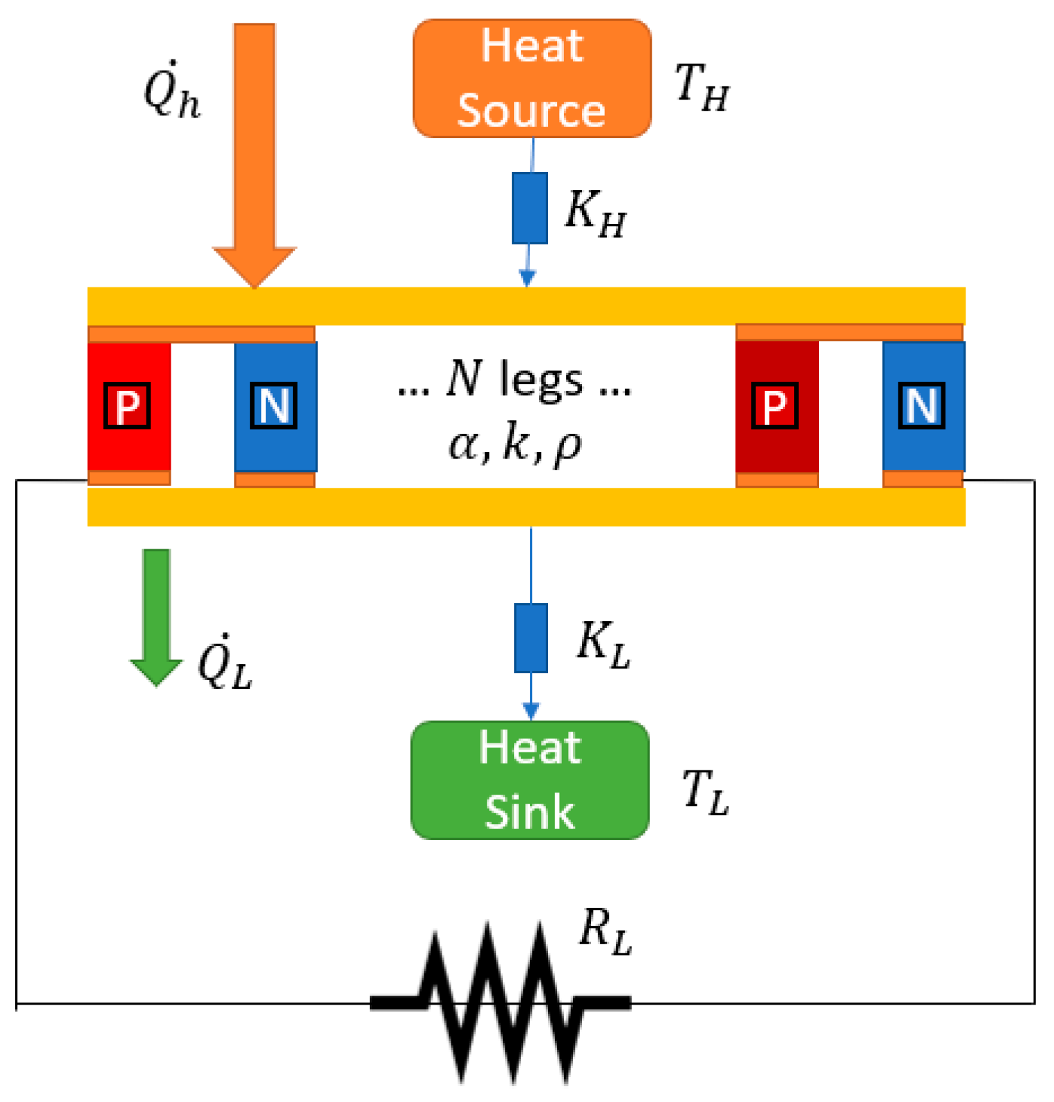
Figure 1. One-dimensional representation of a TEM.
The electrical resistance network presented in Figure 2 shows the connections of N legs (P and N type) in series through conductive material tabs. It shows that a TEG system can be modeled as a voltage source (V) in series with a TEG internal resistance.
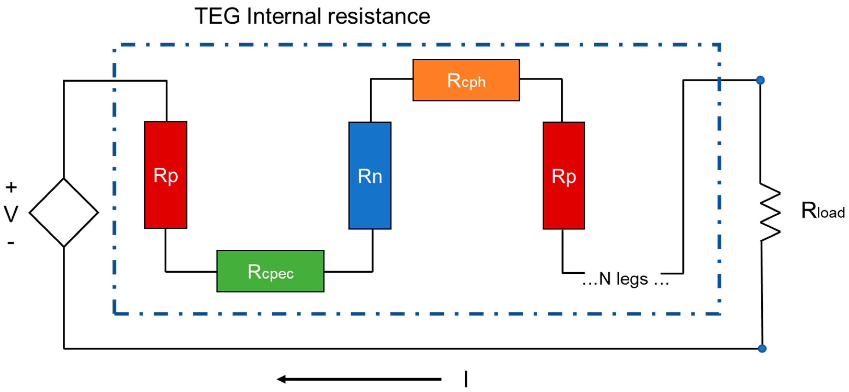
Figure 2. Electrical representation of a TEM.
The Rp and Rn are electrical resistance associated with P and N type semiconductor legs, respectively. Rcpec and Rcph are the electrical resistance of material-conductive strips on the hot side, the electrical resistance of material-conductive strips on the cold side, respectively, and RLoad correspond to the external load resistance.
Figure 3 shows a 3D view of a thermoelectric generator in a flat plate geometry; the filler and the thermal interface layer (TIL) could vary according to the application (this is just a general representation of a TEG module).
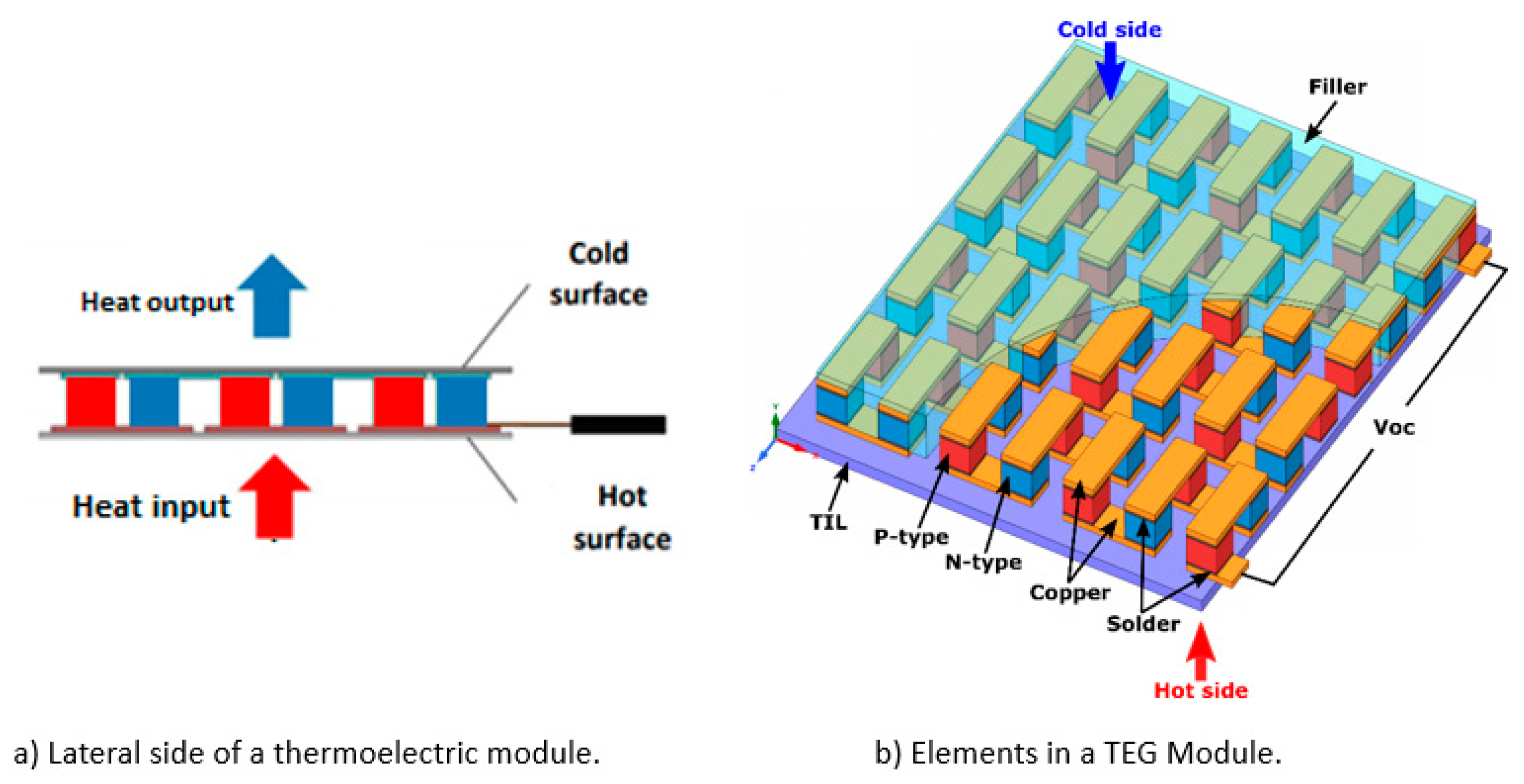
Figure 3. Typical element configuration in a flat thermoelectrical module (TEM). (a) Lateral view of the thermoelectric module; (b) Material elements on thermoelectric modules.
The module in Figure 3 consists of two types of semiconductors: positive (P-type) and negative (N-type), where the P-type has surplus holes, and the N-type is carried by negative charges (electrons) to carry the thermoelectric current. The electrons move from one leg to another when the heat flows from the hot surface to the low-temperature surface; this movement converts the heat flux into electrical energy and produces power to interact with an electrical load.
2. The Onsager Relationships
In 1930, Lars Onsager published his famous work “Reciprocal relations in irreversible processes” [9], which was one of the most ingenious ways to describe the interference of two (or more) irreversible and simultaneous transport processes (i.e., heat and electrical conduction). When two different materials are coupled and an electric current pass through the junction, absorption of heat occurs and it is called the Peltier Effect. On the contrary, if two opposite junctions are maintained at different temperatures, an electromotive force (voltage) will appear in the circuit. Onsager presented a practical way to understand, in general, the coupled effect under the hypothesis of a linear response between the fluxes and forces responsible for the simultaneous transport phenomena. Equation (1) is presented as follows:
where Jk represents the flux, Fj is the driven forces, and Ljk are the phenomenological coefficients. According to the Curie principle [10], for isotropic systems, symmetries concerning the phenomenological coefficients lead to fluxes that will not be dependent on all the possible forces, i.e., currents and forces of differing tensorial order will not interact with each other. The Onsager’s reciprocity relations present symmetry among thermodynamic cross-effects, the j-th general force takes place in the creation of the k-th flux just with the same weighting factor as the k-th force. Mathematically, it is easy to show according to Equation (2):
Jk = ∑j Ljk Fj (1)
Ljk = Lkj (2)
3. The Seebeck Effect
The principle of a TEG module is the Seebeck effect. When a thermoelectric coupled has a heat source, and it applies heat energy to create a temperature difference between both sides of the P–N couple, an electrical current is induced in the circuit, and that electric current indicates that a voltage is created due to the movement of heat. In 1794, Alessandro Volta discovered this phenomenon, but thanks to T.J. Seebeck’s works on thermoelectric forces, the effect adopted his name [11]. The Seebeck coefficient, α(T), can be expressed according to Equation (3):
α(T) = −grad(φ)/grad(T) (3)
Here, φ represent the voltage, T temperature, and α(T) is the combined coefficient related to material Seebeck properties used in P–N coupled. Usually, α(T) of the junction between two materials is the difference between the two absolute parameters properties of each material.
4. The Peltier Effect
The principle of a TEG Opposite to the Seebeck effect, the junction of two different isothermal materials with an electron current flow across them, produces a heat rejection or absorption according to the current direction. Usually, the Peltier effect is explained by the change in the average kinetic energy of a charge carrier (the electron) when the junction is crossed [12]. Equation (4) shows the Peltier coefficient (π) as the relation between the heat transfer rate from the union (Q) and the current flowing through them (I).
π = Q/T (4)
5. The Thomson Effect
In 1854, William Thomson (Lord Kelvin) discovered that there is an extra reversible heat flux in excess of the Joule dissipation heat when a homogeneous material is exposed simultaneously to a thermal gradient and an electric current flow. The thermodynamic analysis for TEG, including this effect, has been widely presented. Zhang et al. [13] analyzed the influences of the Thomson effect on the power output of a thermoelectric generator; they found the difference between the conversion efficiencies with the Thomson effect, and, without the Thomson effect, it increases fast with the temperature difference between the hot and cold ends. This effect has also been studied in different leg geometries [14][15]; the authors concluded the Thomson effect lowers the performance of a thermoelectric generator. The Thomson coefficient can be related to the Seebeck coefficient through Equation (5).
τ(T) = T (δα/δT) (5)
References
- Wang, X.D.; Huang, Y.X.; Cheng, C.H.; Lin, D.T.; Kang, C.H. A three-dimensional numerical modeling of ther-moelectric device with consideration of coupling of temperature field and electric potential field. Energy 2012, 47, 488–497.
- Enn Velmre, Thomas Johann Seebeck (1770–1831). Est. J. Eng. 2007, 13, 276–282.
- Stockolm, J. Générateurs Thermo-Électriques. Journées Electrotechniques du Club EEA. 2003, pp. 15–21. Available online: https://www.researchgate.net/publication/228925386_GENERATION_THERMOELECTRIQUE (accessed on 15 November 2022).
- Elsheikh, M.H.; Shnawah, D.A.; Sabri, M.F.M.; Said, S.B.M.; Hassan, M.H.; Bashir, M.B.A.; Mohamad, M. A review on thermoelectric renewable energy: Principle parameters that affect their performance. Renew. Sustain. Energy Rev. 2014, 30, 337–355.
- Söylemez, E.; Alpman, E.; Onat, A. Experimental analysis of hybrid household refrigerators including thermoelectric and vapour compression cooling systems. Int. J. Refrig. 2018, 95, 93–107.
- Wang, Y.; Zhang, H.; Hao, H.; Li, H. Performance assessment and parametric study of a hybrid system consisting of an alkali metal thermoelectric converter and an absorption refrigerator. Energy Convers. Manag. 2019, 188, 346–353.
- Zheng, X.; Liu, C.; Yan, Y.; Wang, Q. A review of thermoelectrics research—Recent developments and potentials for sustainable and renewable energy applications. Renew. Sustain. Energy Rev. 2014, 32, 486–503.
- Champier, D. Thermoelectric generators: A review of applications. Energy Convers. Manag. 2017, 140, 167–181.
- Onsager, L. Irreversible Processes. Phys. Rev. 1931, 37–38, 183–196.
- Kirschner, I.; Molnár, P. Relation between Curie’s principle and Onsager’s reciprocity. Acta Phys. Hung. 1989, 66, 277–287.
- Beretta, D.; Neophytou, N.; Hodges, J.M.; Kanatzidis, M.G.; Narducci, D.; Martin-Gonzalez, M.; Beekman, M.; Balke, B.; Cerretti, G.; Tremel, W.; et al. Thermoelectrics: From history, a window to the future. Mater. Sci. Eng. R Rep. 2019, 138, 100501.
- Munera, F. Desarrollo de un Modelo Matemático Fenomenológico que Permita Simular el Comportamiento de Sistemas Termoeléctricos. 2012, p. 98. Available online: https://repositorio.unal.edu.co/handle/unal/11246?show=full (accessed on 15 November 2022).
- Zhang, M.; Tian, Y.; Xie, H.; Wu, Z.; Wang, Y. Influence of Thomson effect on the thermoelectric generator. Int. J. Heat Mass Transf. 2019, 137, 1183–1190.
- Kaushik, S.C.; Manikandan, S. The influence of Thomson effect in the energy and exergy efficiency of an annular ther-moelectric generator. Energy Convers. Manag. 2015, 103, 200–207.
- Lamba, R.; Kaushik, S. Thermodynamic analysis of thermoelectric generator including influence of Thomson effect and leg geometry configuration. Energy Convers. Manag. 2017, 144, 388–398.
More
Information
Subjects:
Engineering, Electrical & Electronic
Contributor
MDPI registered users' name will be linked to their SciProfiles pages. To register with us, please refer to https://encyclopedia.pub/register
:
View Times:
1.7K
Revisions:
5 times
(View History)
Update Date:
20 Jan 2023
Table of Contents


Notice
You are not a member of the advisory board for this topic. If you want to update advisory board member profile, please contact office@encyclopedia.pub.
OK
Confirm
Only members of the Encyclopedia advisory board for this topic are allowed to note entries. Would you like to become an advisory board member of the Encyclopedia?
Yes
No
${ textCharacter }/${ maxCharacter }
Submit
Cancel
Back
Comments
${ item }
|
${ item.createdUser.fullName }
${ item.createdAt }
${ item.vote }
${ item.reply }
Delete
${ reply.createdUser.fullName }
${ reply.createdAt }
${ reply.vote }
Delete
There is no reply to this comment~
${ item.replyTextCharacter }/${ item.replyMaxCharacter }
Submit
Cancel
More
No more~
There is no comment~
${ textCharacter }/${ maxCharacter }
Submit
Cancel
${ selectedItem.replyTextCharacter }/${ selectedItem.replyMaxCharacter }
Submit
Cancel
Confirm
Are you sure to Delete?
Yes
No