Your browser does not fully support modern features. Please upgrade for a smoother experience.

Submitted Successfully!
Thank you for your contribution! You can also upload a video entry or images related to this topic.
For video creation, please contact our Academic Video Service.
| Version | Summary | Created by | Modification | Content Size | Created at | Operation |
|---|---|---|---|---|---|---|
| 1 | André Pereira | -- | 1386 | 2023-01-09 23:00:50 | | | |
| 2 | Conner Chen | + 9 word(s) | 1395 | 2023-01-10 07:59:10 | | |
Video Upload Options
We provide professional Academic Video Service to translate complex research into visually appealing presentations. Would you like to try it?
Cite
If you have any further questions, please contact Encyclopedia Editorial Office.
Pereira, A.F.C.; Sousa, J.M.M. Types of Airborne Wind Energy Systems. Encyclopedia. Available online: https://encyclopedia.pub/entry/39928 (accessed on 08 February 2026).
Pereira AFC, Sousa JMM. Types of Airborne Wind Energy Systems. Encyclopedia. Available at: https://encyclopedia.pub/entry/39928. Accessed February 08, 2026.
Pereira, André F. C., João M. M. Sousa. "Types of Airborne Wind Energy Systems" Encyclopedia, https://encyclopedia.pub/entry/39928 (accessed February 08, 2026).
Pereira, A.F.C., & Sousa, J.M.M. (2023, January 09). Types of Airborne Wind Energy Systems. In Encyclopedia. https://encyclopedia.pub/entry/39928
Pereira, André F. C. and João M. M. Sousa. "Types of Airborne Wind Energy Systems." Encyclopedia. Web. 09 January, 2023.
Copy Citation
Airborne wind energy (AWE) has received increasing attention, with the goal of achieving electricity generation solutions that may be used as a complement or even an alternative to conventional wind turbines. There are several ways to classify AWE systems, e.g., with respect to the means of electricity generation, the flight principles and operation, or the type of flying wing, to name a few.
airborne wind energy
crosswind systems
design choice factors
1. Introduction
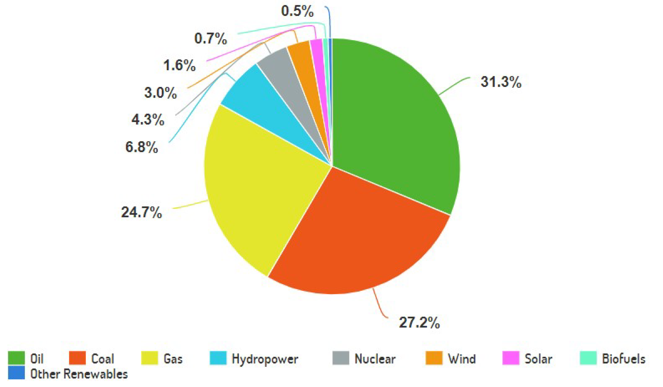
During the last decades, the global energy consumption has been growing, mainly driven by the growth of the industry sector in several countries in the Middle East, Asia, and Africa [1]. The total energy consumption is expected to keep increasing up to 22% by the end of 2050 [2]. Although this increase embodies a worldwide technological development, it also represents one of the most urgent challenges faced nowadays by humankind. This is mainly due to the fact that, with the current distribution of energy production among the different sources, costs to human health and the environment are becoming unbearable. To date, fossil fuels (coal, natural gas, and oil) account for more than 80% of the global primary energy demand [3], as illustrated in Figure 1.

Figure 1. Global primary energy demand.
The combustion of these fuels releases chemical compounds as sulfur (SOx) and nitrogen oxides (NOx), as well as carbon dioxide (CO2). On one hand, the first two are major air pollutants that cause adverse human health effects, reduction of agricultural yields, damage to forests and fisheries (acid rain), and damage to buildings and infrastructure. On the other hand, the increase of the CO2 concentration in the atmosphere is the main cause of global warming and its ensuing detrimental effects—climate change, biodiversity reduction, and increase of mean sea level, to name a few [4].
In order to address these problems, it is imperative to pursue the usage of a suitable combination of alternative and sustainable energy sources. One of such alternatives is the exploitation of wind energy for electricity production. Nowadays, this resource is mostly explored by using wind turbines (WTs) both on- and offshore. Their main components are the tower (for elevation), the blades (typically three), the nacelle which contains the electric generator, the gearbox, and the control systems. The land occupation of the present wind farms is about 7–8 and 2–3 turbines per km2, respectively, for onshore and offshore, considering 2–4 MW, 90–120 m diameter turbines. The corresponding power output density is about 7 W/m2 onshore and 3 W/m2 offshore, which is 100–300 times lower than that of large thermal plants [5]. Moreover, due to wind intermittency, a wind farm is able to produce an average power that is only a fraction of its rated power (capacity factor). All these issues make current wind energy production not competitive with respect to fossil energies.
According to an assessment carried out by Archer and Caldeira [6], the higher the altitude, the stronger and more consistent the winds are, both on- and offshore. This allows not only increasing rated powers but achieving higher capacity factors as well. For example, in the land mass and coastal areas of Europe at a variable height up to 500 m, the wind power density, which is available 95% of the time, doubles when comparing to that at a fixed height of a conventional WT [7]. Marvel et al. [8] showed that the extraction of “only” 18 TW (i.e., a quantity comparable with the world power demand at today’sdate) of 1800 TW, possible in the whole atmospheric layer, would not produce significant damaging effects at a global scale. Hence, the geophysical potential is huge. Nevertheless, taking advantage of high-altitude wind with the conventional technology would be financially very costly, since higher and structurally more resistant towers would be needed as well as more reliable foundations (the tallest wind turbine is Haliade-X, at 260 m [9]). Additionally, only part of the blades contributes efficiently to power production: the outer 30% of the blades account for more than half of the production [10]. Hence, most of the components serve only as structural support.
Thereby, the scenario of finding a technology capable of harvesting the power from winds at higher altitudes than conventional wind turbines (300 m to 10 km), allowing for larger capacity factors while increasing the productivity of all system constituents, presented itself. Accordingly, the concept of airborne wind energy (AWE) arose, first introduced by [11] in the eighties. Roughly speaking, AWE systems are formed by a flying energy harvesting system, connected to a ground station through a tether, which replaces the conventional WT’s tower and inner part of the blades. This idea represents a substantially smaller material investment per unit of usable power than most other renewable energy sources (90% saving as compared to conventional WTs [12]). However, that comes at a cost: while a conventional wind turbine is a stationary construction on the ground, an AWE system operates while flying and, whenever a malfunction occurs, the prospect of a total system destruction comes to light. As a consequence, there are several aspects that must be taken into account in the choice and design of these systems. In addition, despite the high power-to-mass ratio promised by AWE, there is still no mature technology available in the market to enable the large-scale deployment of this technology at comparably low costs. Only in the most recent years have companies such as Kitepower and SkySails commercially deployed systems in the Caribbean [13] and Mauritius islands [14], respectively.
2. Types of Airborne Wind Energy Systems
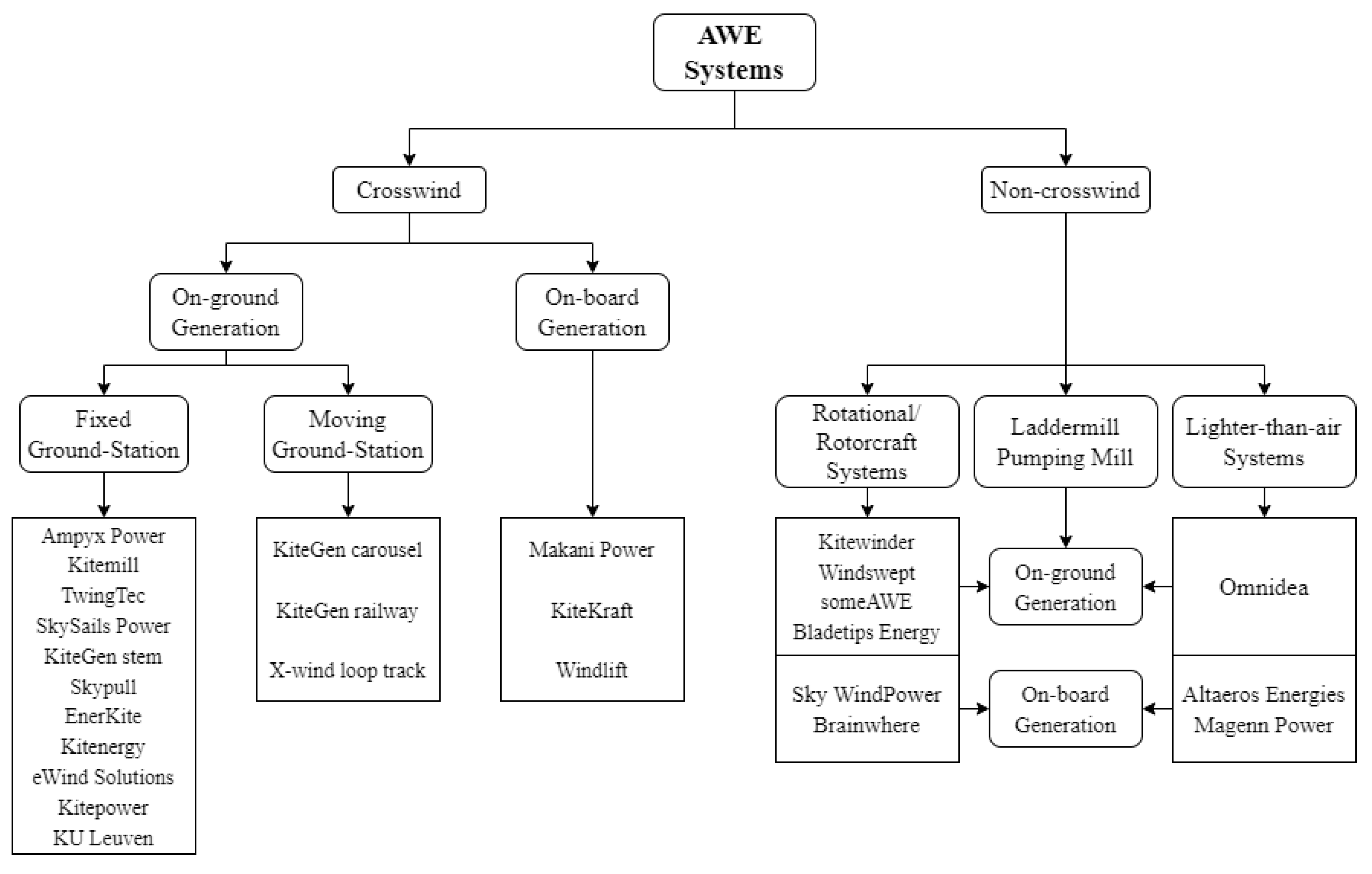
There are several ways to classify AWE systems, e.g., with respect to the means of electricity generation, the flight principles and operation, or the type of flying wing, to name a few. The aim of this section is to present a general description of the existing systems, and categorize them. This classification is summarized in Figure 2, where a list of companies/research institutions with accomplished work in prototypes of each category is also provided.

Figure 2. Classification of AWE systems, with list of institutions and developed prototypes.
In the first sublevel, these systems are separated according to their in-flight behavior, i.e., if they are subjected to crosswind motion or not. The benefits of flying in crosswind were introduced by Loyd [11]. It basically consists of flying in a transverse direction (or close to it) with respect to the wind flow, which can be implemented through reciprocating patterns, such as figure eights, or returning patterns, such as circles. Usually, the former pattern is preferred since it avoids the twisting of the tether [15]. This kind of motion also allows an increase of the relative velocity of the flying wing.
Crosswind systems are then divided into two groups in line with the location of their electricity generators, which also coincides with the distinction between lift-mode and drag-mode given by Loyd. Power production can be achieved either in a ground station or on-board of the flying wing. Here, the flying wing carries on-board generators and sends down the electric current through the tether.
Despite belonging to the same categories, all the systems show certain singularities distinguishing them, such as wing rigidity, flight control, take-off and landing operations, and more.
It is noteworthy that the Alphabet’s subsidiary Makani Power, the main pursuer of on-board generation systems, was shut down in February 2020. The reason given for this outcome was the fact that “the road to commercialization is longer and riskier than hoped”, and that those risks would “outweigh the potential upsides” [16]. In addition, Ampyx Power, explorer of the lift-mode concept, failed to find financial investment and went bankrupt [17].
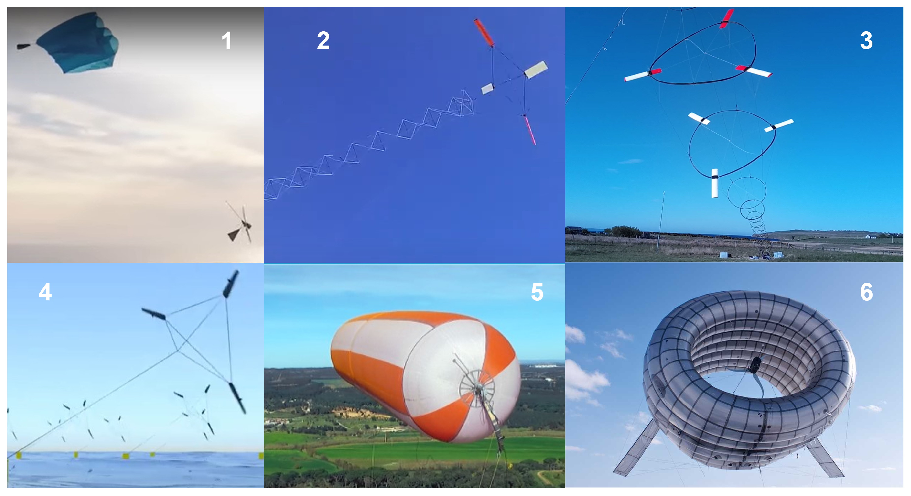
With respect to noncrosswind systems, a separation of concepts is performed based on the flight operation along with the aircraft configuration. One distinguishes between systems that are fully in rotation (circular flight path) or use rotorcrafts to produce electricity, and systems that use the buoyancy flying principle (meaning that a lighter-than-air gas is utilized). Illustrations of some of these kind of systems, per institution, are showcased in Figure 3. Systems only requiring aerostatic lift are also mentioned, such as the ladder and pumping mill [18]. In addition, it is also possible to establish the distinction between on-ground and on-board generation.

Based on the number of institutions with developed technology in each category, a clear preference for crosswind systems may be identified. In fact, Loyd [11] showed that the power output was larger in these systems due to the increase in relative velocity of the flying wing.
References
- Enerdata. Total Energy Consumption. Available online: https://rb.gy/kxsbv8 (accessed on 15 March 2022).
- Enerdata. Total Primary Energy Consumption. Available online: https://rb.gy/taiw22 (accessed on 15 March 2022).
- Ritchie, H.; Roser, M. Energy. Available online: https://rb.gy/xzrx9v (accessed on 15 March 2022).
- Markandya, A.; Saygin, D.; Miketa, A.; Gielen, D.; Wagner, N. The True Cost of Fossil Fuels: Saving on the Externalities of Air Pollution and Climate Change; Technical Report; International Renewable Energy Agency: Abu Dhabi, United Arab Emirates, 2016; ISBN 978-92-95111-87-5.
- Enevoldsen, P.; Jacobson, M.Z. Data investigation of installed and output power densities of onshore and offshore wind turbines worldwide. Energy Sustain. Dev. 2020, 60, 40–51.
- Archer, C.L.; Caldeira, K. Global Assessment of High-Altitude Wind Power. Energies 2009, 2, 307–319.
- Bechtle, P.; Schelbergen, M.; Schmehl, R.; Zillmann, U.; Watson, S. Airborne wind energy resource analysis. Renew. Energy 2019, 141, 1103–1116.
- Marvel, K.; Caldeira, K.; Kravitz, B. Geophysical limits to global wind power. Nat. Clim. Chang. 2013, 3, 118–121.
- GE Renewable Energy. Meet the Haliade-X-Powering 16,000 Homes. Available online: https://www.ge.com/renewableenergy/stories/new-wind-turbine-to-increase-efficiency-in-offshore-wind-farms (accessed on 16 March 2022).
- Burton, T.; Jenkins, N.; Sharpe, D.; Bossanyi, E. Wind Energy Handbook, 2nd ed.; John Wiley & Sons: Hoboken, NJ, USA, 2011.
- Loyd, M.L. Crosswind Kite Power. J. Energy 1980, 4, 106–111.
- Khan, Z.; Rehan, M. Harnessing Airborne Wind Energy: Prospects and Challenges. J. Control. Autom. Electr. Syst. 2016, 27, 728–740.
- PR.com. Airborne Wind Energy Takes Off in the Caribbean with Kitepower. Available online: https://www.pr.com/press-release/846763 (accessed on 23 March 2022).
- SkySails Power. Kitepower for Mauritius. Available online: https:://skysails-poer.com/kite-power-for-mauritius (accessed on 23 March 2022).
- Fechner, U.; Schmehl, R. Model-Based Efficiency Analysis of Wind Power Conversion by a Pumping Kite Power System. In Airborne Wind Energy, 1st ed.; Ahrens, U., Diehl, M., Schmehl, R., Eds.; Green Energy Technology; Springer: Berlin/Heidelberg, Germany, 2014; Chapter 14; pp. 248–269.
- Insider. Google’s Parent Company Is Shutting Down Power-Generating Kite Subsidiary Makani: ‘The Road to Commercialization Is Longer and Riskier Than Hoped’. Available online: https://www.businessinsider.com/makani-power-generating-kite-shutting-down-2020-2 (accessed on 23 March 2022).
- Silicon Canals. The Hague-Based Ampyx Power Goes Bankrupt; Fails to Find Investors for Its Airborne Wind Energy Technology. Available online: https://siliconcanals.com/news/startups/ampyx-power-bankrupt-wind-energy-technology/ (accessed on 23 June 2022).
- Ockels, W.J.; Lansdorp, B. Comparison of concepts for high-altitude wind energy generation with ground based generator. In Proceedings of the 2nd China International Renewable Energy Equipment & Technology Exhibition and Conference, Beijing, China, 7–8 November 2005.
- Kitewinder. Available online: https://kitewinder.fr/ (accessed on 28 March 2022).
- Some Airborne Wind Energy How to MAKE the MAR3 Airborne Wind Energy System. Available online: https://someawe.org/ (accessed on 28 March 2022).
- Windswept & Interesting Ltd Kite Turbines. Available online: https://windswept-and-interesting.co.uk/ (accessed on 28 March 2022).
- Brainwhere. Available online: https://www.brainwhere.com/ (accessed on 28 March 2022).
- Omnidea Aerial Plataforms. Available online: https://www.omnidea.net/aerial-platforms.html (accessed on 28 March 2022).
More
Information
Subjects:
Energy & Fuels
Contributors
MDPI registered users' name will be linked to their SciProfiles pages. To register with us, please refer to https://encyclopedia.pub/register
:
View Times:
2.0K
Revisions:
2 times
(View History)
Update Date:
10 Jan 2023
Notice
You are not a member of the advisory board for this topic. If you want to update advisory board member profile, please contact office@encyclopedia.pub.
OK
Confirm
Only members of the Encyclopedia advisory board for this topic are allowed to note entries. Would you like to become an advisory board member of the Encyclopedia?
Yes
No
${ textCharacter }/${ maxCharacter }
Submit
Cancel
Back
Comments
${ item }
|
More
No more~
There is no comment~
${ textCharacter }/${ maxCharacter }
Submit
Cancel
${ selectedItem.replyTextCharacter }/${ selectedItem.replyMaxCharacter }
Submit
Cancel
Confirm
Are you sure to Delete?
Yes
No


