Submitted Successfully!
To reward your contribution, here is a gift for you: A free trial for our video production service.
Thank you for your contribution! You can also upload a video entry or images related to this topic.
Version Summary Created by Modification Content Size Created at Operation
1 -- 4189 2023-01-06 07:24:01 |
2 update references and layout -84 word(s) 4105 2023-01-06 09:27:00 |

Video Upload Options

Do you have a full video?

Confirm

Are you sure to Delete?
Cite
If you have any further questions, please contact Encyclopedia Editorial Office.
Khedr, M.;  Hamada, A.;  Järvenpää, A.;  Elkatatny, S.;  Abd-Elaziem, W. Solid-State Welding of Steels. Encyclopedia. Available online: https://encyclopedia.pub/entry/39820 (accessed on 18 April 2024).
Khedr M,  Hamada A,  Järvenpää A,  Elkatatny S,  Abd-Elaziem W. Solid-State Welding of Steels. Encyclopedia. Available at: https://encyclopedia.pub/entry/39820. Accessed April 18, 2024.
Khedr, Mahmoud, Atef Hamada, Antti Järvenpää, Sally Elkatatny, Walaa Abd-Elaziem. "Solid-State Welding of Steels" Encyclopedia, https://encyclopedia.pub/entry/39820 (accessed April 18, 2024).
Khedr, M.,  Hamada, A.,  Järvenpää, A.,  Elkatatny, S., & Abd-Elaziem, W. (2023, January 06). Solid-State Welding of Steels. In Encyclopedia. https://encyclopedia.pub/entry/39820
Khedr, Mahmoud, et al. "Solid-State Welding of Steels." Encyclopedia. Web. 06 January, 2023.
Solid-State Welding of Steels
Edit

Welding is a joining process that permanently connects solid parts and forms components that cannot be divided without causing damage. Furthermore, welding is the most efficient and economical way to join similar or dissimilar materials with or without using filler material, heat, or external pressure. Welding can be processed in a variety of environments, including outdoors, inside, underwater, and even in outer space. The two main categories of welding methods, solid-state welding (SSW) and fusion welding, are processes to join metals. Fusion welding can be defined as the melting process of parent materials on facing surfaces with a filler material to form a weld bead. The fusion welding process comprises gas welding, arc welding, and intense-energy beam welding.

solid-state welding diffusion bonding friction stir processing steel

1. Solid-State Welding (SSW)

SSW can be defined as welding processes in which welding is performed through coalescence at a lesser temperature than the base material’s melting temperature and without using filler metal. In some SSW processes, pressure can be used. The advantages of SSW joints can be summarized as follows: SSW techniques are typically free of several solidification defects, such as hot cracking, gas porosity, and nonmetallic inclusions, which may be present throughout fusion-welding processes [1][2][3]. The welded materials’ bonding is due to their interface atoms [4]. Thus, processes of SSW may alternatively be referred to as “solid-state bonding” [1]. Additionally, the welded zone’s mechanical properties are nearly identical to or very close to those of the base metals. Solid-state welding techniques can easily weld dissimilar joints such as Al/Steel alloys, Al/Cu alloys, Cu/Ti alloys, Al/Mg alloys, and W-Cu/Cu alloys, among others [5][6][7][8]. However, SSW has some limitations. To improve the contact between the two base metals, SSW usually requires careful surface preparation before welding, such as oxide removal, degreasing, brushing, and/or sandblasting [9][10][11]. Additionally, most SSW equipment is expensive compared to ordinary fusion welding techniques.

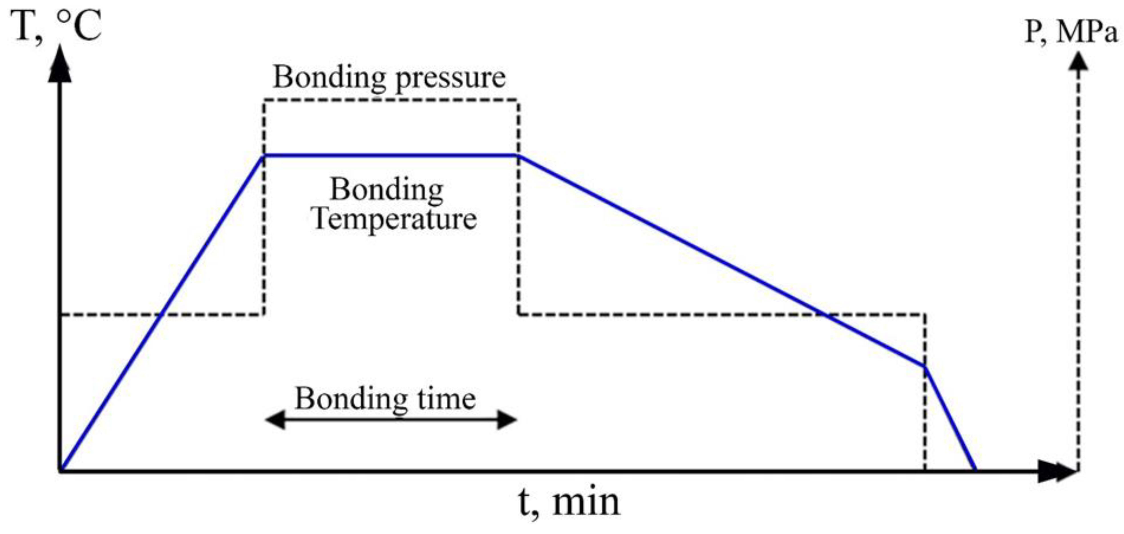
2. Diffusion Bonding (DB)
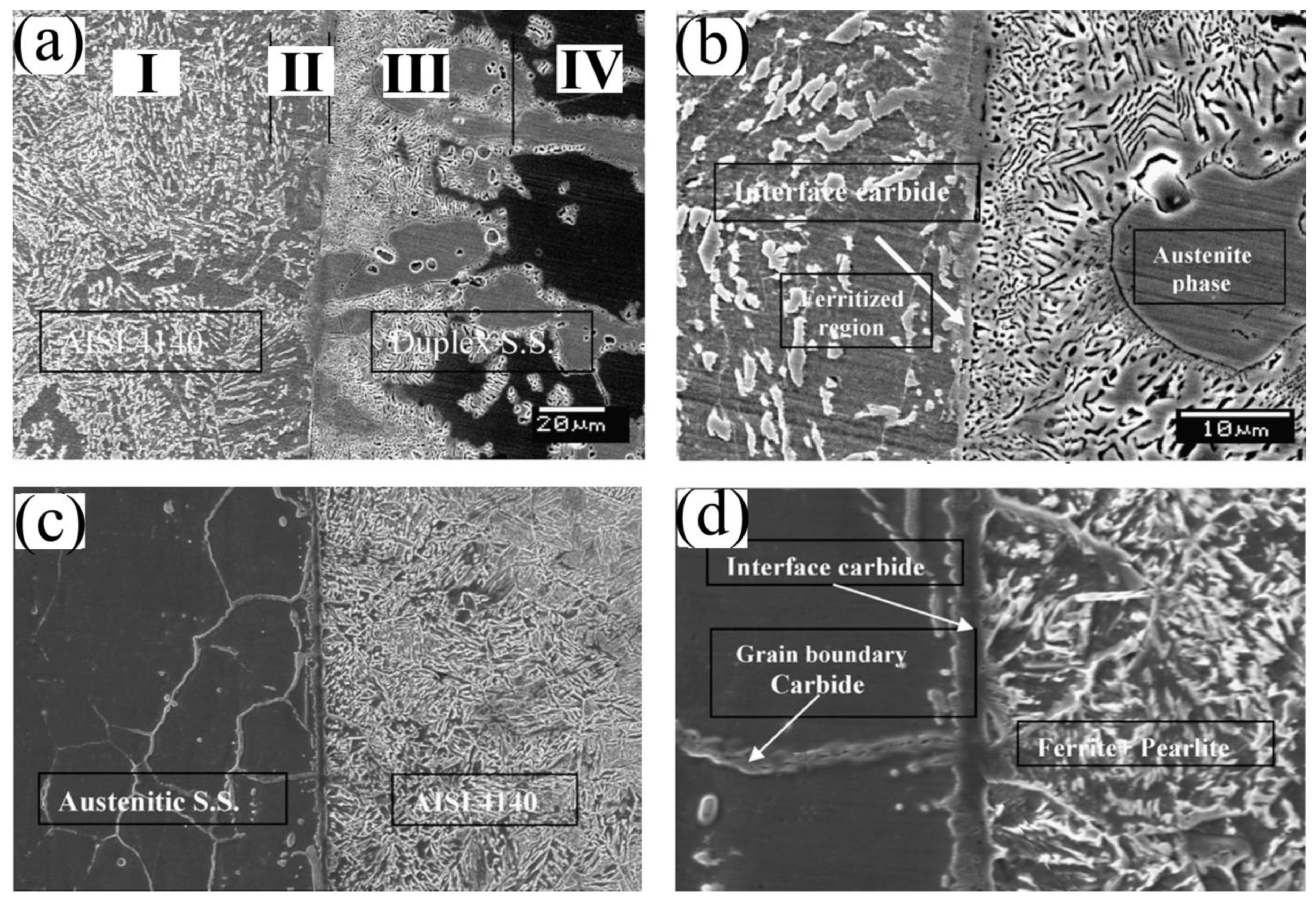
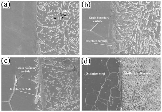
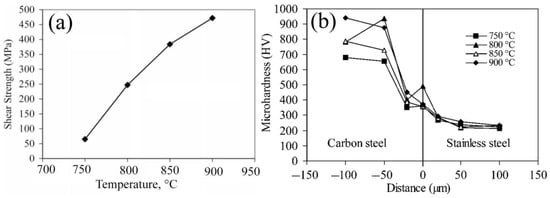
DB is a solid-state joining technique that can be achieved with no need for a liquid interface, brazing, or cast product creation through melting and solidification [12]. DB can produce a solid-state bond between similar and different materials under a certain load at temperatures less than the melting temperature of the welded materials. An inert atmosphere or vacuum (a nonoxidizing environment) is required to protect the faying surface from oxidation. DB is based on the solid-state diffusion principle, in which the atoms of the solid materials intersperse themselves over time at high temperatures and pressure to form a high-quality bond between the base materials. DB can eliminate defects, segregation problems, distortion stresses, and cracking that are usually formed in liquid-phase welding techniques [13]. However, DB is generally associated with a certain deformation at the interface of the joined components [14][15]. This deformation mainly depends on three crucial parameters: bonding temperature, bearing pressure, and bonding time, as illustrated in Figure 1. Therefore, predicting the deformation of a new design is quite challenging because of the non-linear impact of both bearing pressure and temperature [16][17]. In the DB process, the components are fixed and heated to reach the desired bonding temperature. Then, the pressure is applied and raised to the bonding pressure. Both the welding temperature and bonding pressure are maintained at a constant level throughout the holding time of the bonding process. Following the holding time, the pressure is typically lowered to its initial value to fix the samples (see Figure 1), and the temperature is reduced gradually to room temperature. The bonding temperature, time, and applied pressure have been illustrated in various literature works [14][15][16][17][18][19][20][21][22]. Fick’s first law [23] can be implemented to describe the DB process as follows:
where D, Do, R, and Q are the diffusivity at temperature T, the frequency factor, the gas constant, and the activation energy, respectively.
Figure 1. Overview of the reported parameters of the diffusion bonding process: bonding temperature, bonding pressure, and bonding time [23].
Atomic diffusion usually occurs between faying surfaces before the DB temperature is reached and similarly still occurs as the sample cools.
It is well established that the mechanism of solid-state bonding of alloys is divided into six stages, as illustrated in Figure 2. In the first stage (A), the two surfaces are in contact since better direct contact between two surfaces depends on the physical parameters related to the contact surfaces, such as irregularity, clearness, roughness, and surface treatment. In the second stage (B), DB is induced by applying microplastic deformation at the interface. Consequently, voids will form and align at the interface. At subsequent stage (C), the temperature increases to absorb the gas inside voids. The fourth stage (D) includes void shrinkage at the interface due to diffusion creep. In the fifth stage (E), the voids smaller than the critical size are unstable and will disappear rapidly. In the final stage (F), a free-void interface without discontinuity at the bonding interface is promoted. Interestingly, the bonding interface can be microscopically distinguished as a straight line.
During the last two stages, the interfacial grain boundaries migrate out of the joint plane to the lower-energy equilibrium. As the boundaries move, the remaining voids are absorbed within the grains, where they are no longer in contact with a grain boundary. Diffusion processes and creep/super-plasticity move atoms from adjacent areas to the void surfaces, decreasing the volume of interfacial voids.
Eventually, if satisfactory time is permitted, the voids will be eliminated through volume diffusion, and the atom-to-atom bond across the original interface will form during the third stage. However, the bonding does not contain melting or gross macroscopic interface distortion; thus, the bond area microstructure is like that of the areas remote from the joint and has the properties of the parent metal [24][25].
Figure 2. Schematic illustration of the solid-state diffusion bonding stages: (A) the first stage: surface contact, (B) the second stage: onset of diffusion bonding, (C) the third stage: evacuation of gases from the voids, (D) the fourth stage: voids shrinkage, (E) the fifth stage: voids elimination, and (F) the sixth stage: formation of a voids-free interface [25].

2.1. DB of Steels

Duplex stainless steel is utilized in numerous industries, including gas and oil, petrochemicals, paper and pulp, and pollution control. Austenite stainless steel is utilized in severe and mildly corrosive environments. The fusion welding of austenitic stainless steel is typically a part of a system with low-temperature toughness and reduced corrosion resistance; consequently, it represents a limiting factor in material applications. The heat of fusion welding can cause grain coarsening in the heat-affected zone (HAZ), in addition to solidification cracking in the stainless-steel welded metal.
Compared to previous challenges, DB does not involve melting or gross macroscopic interface distortion. In addition, the lack of a fused zone in DB welding is attractive to alloys prone to segregation effects.
Kurt [12] investigated the DB of austenitic and duplex stainless steel to medium-carbon steel. Figure 3a shows the microstructure of the bonding interface between the medium-carbon steel AISI 4140 and duplex stainless steel, which displays good bonding along the interface without discontinuities or microcracks. Four distinct zones could be observed in the microstructure of the bonded dissimilar joint. Zone (I) shows the microstructure of the base metal carbon steel AISI 4140 that exhibits a ferrite-pearlite structure, Zone (II) is a ferrite stabilized region on the carbon steel side, Zone (III) shows a carbide network in the stainless-steel side, and zone (IV) displays the microstructure of the other base metal duplex stainless steel, ferrite-austenite.
Figure 3. Microstructure of the bonding interface of medium-carbon steel AISI 4140 with a duplex stainless steel (a,b) and 304 austenitic stainless steel (c,d) showing: (a) defect-free interface, (b) carbide network in the stainless-steel side and carbide in the interface, (c) sound bounding interface, and (d) carbide forming on the interface [12].
Figure 3b reveals a network of carbide on the stainless-steel side and a layer of chromium-carbide on the interface. The diffusion of carbon into duplex stainless steel caused the formation of chromium-carbide around austenite grains in the ferrite phase. Carbon diffused more slowly in austenite than in the ferrite phase. Thus, carbon diffused longer in the ferrite phase, and the carbon atoms left the ferritic structure and bonded to Cr when it cooled. The Cr in carbon steel stabilized the ferrite phase and resulted in the formation of ferrite and spheroidized cementite, as depicted in Figure 3c. It was reported that adding Cr by only 0.4 wt.% of Cr to steel stabilized the ferrite in the two-phase region [26].
On the other hand, regarding the interface microstructure of the bonded medium-carbon steel and austenitic stainless-steel joint, Figure 3c,d also exhibit respectable bonding along the bonded joint’s interface. Moreover, the interface was free of micro-voids and discontinuities. However, at the grain boundaries and interface region of austenitic stainless steel, the chromium carbide formed by diffusing C from the medium-carbon steel side. The shear strength of the bonded duplex stainless steel/medium-carbon steel was 767 MPa; however, the austenitic stainless steel/-medium-carbon steel joint recorded 475 MPa. Such variation can be attributed to the interface carbide amount and the ferritized zone width toward the medium-carbon steel side. As can be seen in Figure 3, the interface carbide width in the medium-carbon steel/austenitic stainless-steel joint is higher than that in the medium-carbon steel joint.
Zhang et al. [27] studied the bonding time effect on the martensitic stainless-steel joint quality. It was found that as time increases, the large voids in the bonding interface become smaller, resulting in an increase in the interface bonding ratio.
Huo et al. [28] studied the effect of the post-weld heat-treatment process and DB time on the microstructural and mechanical properties of the diffusion-affected zone by carrying out a DB test in a vacuum between dissimilar materials: TP347H austenitic heat-resistant steel and high-Cr ferrite heat-resistant steel. It was revealed that the interfacial bonding rate increased progressively when the DB time was increased. In addition, dynamic recrystallization occurred because of the interaction between the deformation storage energy difference and dislocation slip and the fine grains generated at the diffused bonding interface, which formed a serrated interface.
Moreover, Noh and Kasada [29] investigated the solid-state DB at temperatures ranging from 950 °C to 1300 °C and under a pressure of 25 MPa through a high-vacuum hot press of high Cr-ODS ferritic steel. The results showed that a defect-free joint could be obtained at a temperature of 1200 °C and a bonding time of 1 h. The bonding proved ineffective below 1200 °C due to the presence of chromium carbide and micro-voids. When bonding times were less than one hour, a creep-deformed layer and chromium carbide inclusions were detected at the bonded interface.
For simplicity, in the DB process, macroscopic deformations on the order of a few percent may occur due to high compression stress and testing temperatures. The three stages of the DB process can be used to explain how surface evolutions affect bond conditions. In the first stage, the rough surface can deform under stress before heating, resulting in an increase in the contact area. Thus, the deformation processes lead to the collapse of the surface asperities producing a network of sealed pores at the interface before the bonding continues via diffusion-controlled mechanisms such as grain boundary diffusion and power law creep [30].
The second stage involves the softer steel interface experiencing substantial deformation as the temperature increases, resulting in the voids disappearing as well as the initial asperity collapsing, thus resulting in fully intimate contact of the surfaces. It is worth noting that the final structure of the bond line depends on the composition of the surface of the pore and its interior environment. Clean, oxide-free surfaces could produce an ideal line-type bond [30]. Eventually, the final stage involves atomic diffusion at a constant temperature, and this diffusion mechanism is in line with Derby’s theoretical model [31]. Possible mechanisms for DB were identified by this model, which includes: (1) plastic deformation of surface asperities, (2) power law creep deformation of the surface, and (3) diffusion of matter from interfacial void surfaces/bonded regions to growing necks [30].
Wang and Xiu [32] investigated the welding temperature impact of vacuum DB on the evolution of microstructure, interfacial morphology, and mechanical properties of AISI 304 austenite stainless steel and Q235A mild steel. Their results demonstrated that the carbon-enriched and single ferrite layers were formed near the bonding interface of AISI 304 austenite stainless steel and Q235A mild steel. In addition, on both sides of the interface, a heterogeneous microstructure was detected, and common grain boundaries were formed by diffusion. Moreover, the peak toughness and strength of the bonded joint were revealed at an approximate 850 °C welding temperature, 10 MPa welding pressure, and 60 min of welding time, which was higher than the Q235A mild-steel layer. They also demonstrated that the Cr23C6 carbide formed easily at a moderately low temperature (800 °C), whereas the intermetallic compounds and secondary carbide phases formed at a higher temperature (900 °C). Thus, in both cases, forming such a carbide dramatically reduced the bonded joint’s strength and toughness. Thus, in their study, they proposed to effectively avoid the formation of brittle precipitate phases by keeping the welding temperature around 850 °C, thereby ensuring the bonded joint’s performance.
Kurt et al. [33] investigated the influence of the bonding temperature on the microstructural features and shear strength of austenitic stainless steel (AISI 304) and medium-carbon steel (AISI 4140) joined by DB. Figure 4 shows the SEM graphs of the diffusion-coupled interface microstructures at four different temperatures: 750, 800, 850, and 900 °C. The SEM graphs demonstrated good bonding along the bonded joint’s interface at all temperatures. However, there was no considerable microstructural change at 750 °C, as there was no significant diffusion of elements, and only faying surface asperities were flattened. At 850 °C, the chromium carbides were formed at the interface zone because of the diffusion of C from the AISI 4140 side. Furthermore, martensite and partially spheroidized cementite on the AISI 4140 side could be observed. Moreover, increasing the test temperature to 900 °C resulted in a higher diffusion of C, which enlarged the chromium carbide layer in the grain boundary and interface zone; see Figure 4d.
Figure 4. Microstructures of the bonding interface of the joints between AISI 304 austenitic stainless steel and AISI 4140 medium-carbon steel at different temperatures: (a) 750 °C, (b) 800 °C, (c) 850 °C, and (d) 900 °C [33].
Grain boundaries are considered a high-diffusion path. As a result, C diffuses into stainless steel over grain boundaries, so the carbide grain boundaries were formed, as seen in the EDS analysis (Figure 4d). As revealed by EDS analysis, the chemistry of these zones comprises of 5.9 Ni, 10.8 C, 20.8 Cr, and 62.3 Fe (in wt.%). It is well established that Cr and Fe have a significant tendency to form M3C carbides in steel as predicted by the Isopleth equilibrium phase diagram of the system Fe–Cr–C [34]. Figure 5 displays the bonding temperature effect on both the shear strength and hardness of the joints. The joint shear strength increased with the increase in temperature because of the higher mutual diffusion of the constituents to reach its maximum value of 475 MPa at a temperature of 900 °C; see Figure 5a. However, the martensite absence at the interface resulted in a decrease in hardness at the interface zone between AISI 4140 and AISI 304 steel, as seen in the microhardness profiles; see Figure 5b. The hardness decreased in the interface region of the carbon steel side at all temperatures, which is attributed to the diffused chromium, as shown in Figure 4d. Cr develops a ferrite-stabilized zone, thus inhibiting martensite formation.
Figure 5. (a) The effect of bonding temperatures on compressive shear strength of the bonds, and (b) microhardness profiles of diffusion bonded interface [33].

2.2. Defects in Diffusion Bonding

Two-Dimensional Defects

Two-dimensional defects of the metallic lattice include phases and grain boundaries. These defects can affect the DB. Firstly, the dislocation movement is restricted by the grain size; therefore, the grain boundaries are considered obstacles for dislocations to move through the lattice. Consequently, at constant strain, the deformation caused by the dislocation movement is slighter for the material with a small grain size. In the DB process, the applied temperature experienced by the interface region can cause a coarsening of the grain, resulting in softening behavior at the faying surfaces. Second, deformation at high temperatures is characterized by grain boundary sliding, coble creep, or vacancy flow through the volume (Nabarro–Herring creep) [35][36]. Thus, the coarse-grained material will experience a larger deformation through DB due to fewer obstacles to dislocation movement and the tendency of grains to slide against each other. Therefore, the grain size and the applied temperature are two important factors that can govern the deformation degree and the creep rate during DB.

Three-Dimensional Defects (Precipitation)

Dissimilar metal welds of steels represent a model for local precipitation and coupled long-range diffusion occurring during DB. The most extensively investigated dissimilar metal welds are those among two ferrite steels [37][38] with dissimilar chromium contents, in addition to those between austenite stainless steel and low-alloy ferrite steel [39][40]. Moreover, it was revealed that in the similar carbon content of both steels, carbon was diffused to the high-alloyed side from the low-alloyed side [41]. Therefore, in steel metallurgy, carbon is essential, and its distribution has an essential influence on their mechanical properties. In all these cases, the driving force of carbon diffusion is the activity gradient of carbon between both steels, and it cannot be defined by the concentration of carbon only. Moreover, this type of diffusion often causes substantial changes in the microstructure around the interface bonding. In addition, carbide precipitation always occurs faster in ferritic stainless steels than in austenitic ones because of the significant carbon contents; therefore, carbon solubility in the ferritic matrix becomes much lower [42].

3. Friction Stir Welding (FSW) of Steels

FSW is a technique for metal joining in the solid state (in butt or lap positions) via a rotating friction tool. The heat generated between the tool and the material leads to an extremely soft area along the interface of the joints and the friction tool. FSW was broadly applied to non-ferrous alloys, mainly aluminum alloys. Researchers were fascinated by the ability of the FSW of steels to overcome welding defects generated during fusion welding methods of steels. FSW was introduced in 1991 [43]. Later, FSW was considered an optimum choice for welding different grades of steel that possess high melting points and/or suffer from crack formation when welded by conventional fusion methods [44][45][46]. Furthermore, FSW is considered a clean welding technique that provides environmentally friendly joints [47], free of volumetric defects [48].
It is well known that the weld joints produced by FSW have four different zones, specifically the stirring zone (SZ); the thermo-mechanically affected zone (TMAZ), which is caused by the higher temperature and lower strain that occurs during FSW processing; the heat affected zone (HAZ); and the unaffected zone, which is known as the parent metal (PM) or base metal (BM). Specimens welded by the FSW process have HAZs smaller than the specimens joined by fusion welding. For instance, tungsten arc welding was reported to produce HAZs with great widths due to the relatively high heat input [49][50], which may result in the failure of joints created by fusion welding [51]. Comparatively, FSW generates lower heat in the HAZ. Therefore, FSW is preferred for joining steel grades sensitive to thermal cycles rather than fusion welding techniques [52]. Moreover, FSW refines the grain size in the SZ because of the severe plastic deformation carried out by the stirring tool [53], which significantly affects the strength, ductility, and toughness of the FSW joints [54]. On the one hand, during the FSW processes, C and Cr atoms were diffused through the weld metal; consequently, C/Cr-rich regions and depleted zones were formed. This may negatively affect the mechanical properties of the welded joints due to the inhomogeneous distribution of the chemical composition [55][56]. On the other hand, because of the tempered martensite formation and the refined austenite in the SZ, FSW specimens showed higher tensile strength than the specimens joined by activated-gas tungsten arc welding of 9Cr–1Mo and 316LN stainless steel [50].
The FSW process is carried out by a stirring tool that rotates between two fixed sheets or plates as butt or lap joints [57][58]. The circular tool is a non-consumable tool that rotates against the sheet/plate surface under the effect of an axial load. The tool contains a shoulder and a solid surface or threaded cylindrical pin that heats the workpiece [54]. The rotating tool is fixed in a chuck on the headstock of a milling machine or any indigenously built FSW machine. The tool geometry, travel speed, and rotational speed of the tool during FSW, therefore, directly affect the physical, mechanical, and microstructural properties of joints. Thus, increasing the tool travel speed led to lower peak temperatures and a higher strain rate in the WZ [58]. Increasing the rotational speed resulted in a substantial increase in the SZ peak temperature [49][59]. The maximum peak temperature (T) caused in the SZ during FSW of steels can be estimated by using Equation (1) [50].
where ω, ϑ, and Tm are the tool rotational speed (rpm), weld travel velocity (mm.min−1), and melting temperature of BM, respectively; K and α are constants (K = 0.64 and α = 0.04).
Furthermore, Wang et al. [60][61] presented a deeply analytical and comprehensive study of the bonding behavior under various operating conditions of the FSW process. Their model was completely different from other solid-state bonding models as they relied on the well-established knowledge of the grain boundary creep fracture of high-temperature polycrystalline materials rather than rough surface contact and volumetric inter-diffusion for interfacial gap closure (other models).
It was supposed that the interfacial cavities would shrink under the combined action of sintering and applied compressive stresses under the creep-controlled deformation or according to the Hull–Rimmer diffusive process [31]. Their model demonstrated that the solid-state bonding under FSW depends principally on the creep strain rate in the adjourning workpieces, weakly on stress triaxiality, and negligibly on interfacial diffusion. Moreover, the bonding extent increased with the increase in the tool rotational speed and plunging depth or with a decrease in the tool welding speed. The maximum bonding extent in the FSW process, as well as the maximum cladding thickness that can achieve full bonding in the FSW cladding process, was about half of the tool radius.
In the following sections, it is reported the microstructure evolution and mechanical properties of SZ, TMAZ, and HAZ, as well as welding defects accompanying FSW of similar and dissimilar steels. However, the tool design, material selection, and wear behavior are not included here.
The dynamic recrystallization in the SZ occurred because of the significant plastic deformation; thus, the Widmanstatten ferrite structure generated a moderately low dislocation density. Shear bands of subgrains were perpendicularly oriented to the Widmanstatten ferrite plates because of intensive plastic deformation, as shown in Figure 6a. Figure 6b reveals the ferrite-cementite aggregates. The lamellae cementite in the initial microstructure, perlite, is fragmented by the rotating pin stirring effect. Additionally, the SZ hardness rose from 140 to approximately 230 Hv0.3. Moreover, the SZ yield strength increased from 256 to 435 MPa, whereas the tensile strength rose from 457 to 585 mPa without significantly decreasing the ductility.
Figure 6. TEM micrographs at the SZ of the joint structure. (a) Widmanstatten ferrite with shear bands and (b) ferrite-cementite aggregates (FC) with sub-grains formed by dislocations [62].
Kamaraj et al. [63] joined HSLA steel sheets (3mm thickness each) through FSW. The FSW was carried out by a tungsten-rhenium tool at 500 rpm. The traverse speed was diverse from 57 to 97 mm/min with 10 mm/min in step. In their work, the PM microstructure showed the existence of pearlite and ferrite. During FSW, the peak temperature was greater than the allotropic transformation temperature (A3) at the different traverse speeds (57, 67, and 77 mm/min), while it was lower than 600 °C at 87 and 97 mm/min. Furthermore, the weld nugget microstructure exposed the upper bainite phase and the presence of fine ferrite. The traverse speed reduced the amount of upper bainite, as revealed by EBSD, which can be attributed to the peak temperature decrease and the rapid cooling rate. In addition, the grain size decreased with the transverse speed increase.
The weld nugget exhibited higher hardness than the refined ferrite and bainite phases. However, the hardness decreased with the faster traverse speed, which can be attributed to the bainite structure formation reduction and the soft ferrite phase increase.
Furthermore, the strength of the joint at 57 mm/min was 540 MPa, and at 97 mm/min was 407 MPa. A traverse speed below 78 mm/min resulted in a higher strength because of the hard weld nugget. However, an additional increase in the traverse speed led to lower joint strength, which can be attributed to macroscopic defects and poor consolidation. The macroscopic defect-forming tendency increased with the increase in traverse speed; this resulted in a tensile strength reduction. Groove defects and root flaws were detected at a 97 mm/min traverse speed. In addition, using 97 mm/min as the traverse speed did not pass the root bend test.

References

  1. Akca, E.; Gürsel, A. Solid state welding and application in aeronautical industry. Period. Eng. Nat. Sci. PEN 2016, 4, 1–8.
  2. Coronado, J.; Cerón, C. Fracture mechanisms of CTOD samples of submerged and flux cored arc welding. Theor. Appl. Fract. Mech. 2010, 53, 145–151.
  3. Brothers, D.G. The Origin of Acicular Ferrite in Gas Metal Arc and Submerged Arc Welds. Master’s Thesis, Naval Postgraduate School, Monterey, CA, USA, 1994.
  4. Kreye, H. Melting phenomena in solid state welding processes. Weld. J. 1977, 56, 154–158.
  5. Yildirim, S.; Kelestemur, M.H. A study on the solid-state welding of boron-doped Ni3Al–AISI 304 stainless steel couple. Mater. Lett. 2005, 59, 1134–1137.
  6. Al-Sabur, R.K.; Jassim, A.K. Friction stir spot welding applied to weld dissimilar metals of AA1100 Al-alloy and C11000 Copper. In IOP Conference Series: Materials Science and Engineering; IOP Publishing: Philadelphia, PA, USA, 2018.
  7. Reddy, M.G.; Rao, S.A.; Mohandas, T. Role of electroplated interlayer in continuous drive friction welding of AA6061 to AISI 304 dissimilar metals. Sci. Technol. Weld. Join. 2008, 13, 619–628.
  8. Miyashita, Y.; Mutoh, Y.; Akahori, M.; Okumura, H.; Nakagawa, I.; Jin-Quan, X. Laser welding of dissimilar metals aided by unsteady thermal conduction boundary element method analysis. Weld. Int. 2005, 19, 687–696.
  9. El Mahallawy, N.; Fathy, A.; Abdelaziem, W.; Hassan, M. Microstructure evolution and mechanical properties of Al/Al–12% Si multilayer processed by accumulative roll bonding (ARB). Mater. Sci. Eng. A 2015, 647, 127–135.
  10. Mahallawy, N.E.; Fathy, A.; Hassan, M.; Abdelaziem, W. Evaluation of mechanical properties and microstructure of Al/Al–12% Si multilayer via warm accumulative roll bonding process. J. Compos. Mater. 2017, 0021998317692141.
  11. Abdelaziem, W.; ElMahalawy, N.; Hassan, M.; Fathy, A. Effect of wire brushing on cold roll bonding of Al 1050 sheets. Egyptian J. Eng. Sci. Technol. 2015, 18, 3–4.
  12. Kurt, B. The interface morphology of diffusion bonded dissimilar stainless steel and medium carbon steel couples. J. Mater. Process. Technol. 2007, 190, 138–141.
  13. Yılmaz, O. Effect of welding parameters on diffusion bonding of type 304 stainless steel–copper bimetal. Mater. Sci. Technol. 2001, 17, 989–994.
  14. Akhter, J.; Ahmad, M.; Iqbal, M.; Akhtar, M.; Shaikh, M. Formation of dendritic structure in the diffusion zone of the bonded Zircaloy-4 and stainless steel 316L in the presence of Ti interlayer. J. Alloy. Compd. 2005, 399, 96–100.
  15. AlHazaa, A.; Haneklaus, N.; Almutairi, Z. Impulse pressure-assisted diffusion bonding (IPADB): Review and outlook. Metals 2021, 11, 323.
  16. Azizi, A.; Alimardan, H. Effect of welding temperature and duration on properties of 7075 Al to AZ31B Mg diffusion bonded joint. Trans. Nonferrous Met. Soc. China 2016, 26, 85–92.
  17. Li, P.; Wang, L.; Yan, S.; Meng, M.; Xue, K. Temperature effect on the diffusion welding process and mechanism of B2–O interface in the Ti2AlNb-based alloy: A molecular dynamics simulation. Vacuum 2020, 173, 109118.
  18. Akca, E.; Gursel, A. The effect of diffusion welding parameters on the mechanical properties of titanium alloy and aluminum couples. Metals 2017, 7, 22.
  19. Cooke, K.O.; Atieh, A.M. Current trends in dissimilar diffusion bonding of titanium alloys to stainless steels, aluminium and magnesium. J. Manuf. Mater. Process. 2020, 4, 39.
  20. Wang, J.; Li, Y.; Huang, W. Interface microstructure and diffusion kinetics in diffusion bonded Mg/Al joint. React. Kinet. Catal. Lett. 2008, 95, 71–79.
  21. Song, T.; Jiang, X.; Shao, Z.; Fang, Y.; Mo, D.; Zhu, D.; Zhu, M. Microstructure and mechanical properties of vacuum diffusion bonded joints between Ti-6Al-4V titanium alloy and AISI316L stainless steel using Cu/Nb multi-interlayer. Vacuum 2017, 145, 68–76.
  22. Fang, Y.; Jiang, X.; Mo, D.; Song, T.; Luo, Z. Microstructure and mechanical properties of the vacuum diffusion bonding joints of 4J29 kovar alloy and 316L stainless steel using pure cobalt interlayer. Vacuum 2019, 168, 108847.
  23. AlHazaa, A.; Haneklaus, N. Diffusion bonding and transient liquid phase (TLP) bonding of type 304 and 316 austenitic stainless steel—A review of similar and dissimilar material joints. Metals 2020, 10, 613.
  24. Islam, M.; Ridlev, N. Isostatic diffusion bonding of a microduplex stainless steel. Scr. Mater. 1998, 38, 1187–1193.
  25. Lee, H.-S. Diffusion bonding of metal alloys in aerospace and other applications. In Welding and Joining of Aerospace Materials, 2nd ed.; Chaturvedi, M., Ed.; Woodhead Publishing Series Elsevier Ltd.: Cambridge, UK, 2021.
  26. Kim, S.-J.; Gil Lee, C.; Lee, T.-H.; Oh, C.-S. Effect of Cu, Cr and Ni on mechanical properties of 0.15 wt.% C TRIP-aided cold rolled steels. Scr. Mater. 2003, 48, 539–544.
  27. Zhang, C.; Li, H.; Li, M. Formation mechanisms of high quality diffusion bonded martensitic stainless steel joints. Sci. Technol. Weld. Join. 2015, 20, 115–122.
  28. Hua, Y.; Chen, J.; Yu, L.; Si, Y.; Liu, C.; Li, H.; Liu, Y. Microstructure evolution and mechanical properties of dissimilar material diffusion-bonded joint for high Cr ferrite heat resistant steel and austenitic heat resistant steel. Acta Metall. Sin. 2021, 58, 141–154.
  29. Noh, S.; Kasada, R.; Kimura, A. Solid-state diffusion bonding of high-Cr ODS ferritic steel. Acta Mater. 2011, 59, 3196–3204.
  30. Shi, Y.; Liu, J.; Yan, Y.; Xia, Z.; Lei, Y.; Guo, F.; Li, X. Creep properties of composite solders reinforced with nano-and microsized particles. J. Electron. Mater. 2008, 37, 507–514.
  31. Hull, D.; Rimmer, D. The growth of grain-boundary voids under stress. Philos. Mag. 1959, 4, 673–687.
  32. Wang, D.; Xiu, S. Effect of bonding temperature on the interfacial micro-structure and performance of mild steel/austenite stainless steel diffusion-bonded joint. Acta Metall. Sin. 2017, 53, 567–574.
  33. Kurt, B.; Orhan, N.; Ozel, S. Interface microstructure of diffusion bonded austenitic stainless steel and medium carbon steel couple. Sci. Technol. Weld. Join. 2007, 12, 197–201.
  34. Raynor, G.V.; Rivlin, V.G. Phase Equilibria in Iron Ternar Alloys—A Critical Assessment of the Experimental Literature; The Institute of Metals: London, UK, 1988.
  35. Frost, H.J.; Ashby, M.F. Deformation Mechanism Maps: The Plasticity and Creep of Metals and Ceramics; Pergamon press: Elmsford, NY, USA, 1982.
  36. Trapp, J.; Semenov, A.; Nöthe, M.; Wallmersperger, T.; Kieback, B. Fundamental principles of spark plasma sintering of metals: Part III–densification by plasticity and creep deformation. Powder Metall. 2020, 63, 329–337.
  37. Sopoušek, J.; Foret, R.; Jan, V. Simulation of dissimilar weld joints of steel P91. Sci. Technol. Weld. Join. 2004, 9, 59–64.
  38. Race, J.; Bhadeshia, H. Carbon migration across dissimilar steel welds. In International Trends in Welding Science and Technology; ASM International: Almere, The Netherlands, 1993; pp. 1–5.
  39. Gomez, X.; Echeberria, J. Microstructure and mechanical properties of low alloy steel T11–austenitic stainless steel 347H bimetallic tubes. Mater. Sci. Technol. 2000, 16, 187–193.
  40. Silva, C.C.; Miranda, H.C.; de Sant’Ana, H.B.; Farias, J.P. Austenitic and ferritic stainless steel dissimilar weld metal evaluation for the applications as-coating in the petroleum processing equipment. Mater. Des. 2013, 47, 1–8.
  41. Mas, F.; Tassin, C.; Valle, N.; Robaut, F.; Charlot, F.; Yescas, M.; Roch, F.; Todeschini, P.; Bréchet, Y. Metallurgical characterization of coupled carbon diffusion and precipitation in dissimilar steel welds. J. Mater. Sci. 2016, 51, 4864–4879.
  42. Lippold, J.C.; Kotecki, D.J. Welding Metallurgy and Weldability of Stainless Steels; Wiley-Interscience: New York, NY, USA, 2005.
  43. Thomas, W.M.; Nicholas, E.D.; Needham, J.C.; Murch, M.G.; Temple-Smith, P.; Dawes, C.J. International Patent Application PCT/GB92/02203 and GB Patent Application 9125978.8; UK Patent Office: London, UK, 1991; p. 6.
  44. Wang, Y.; Tsutsumi, S.; Kawakubo, T.; Fujii, H. Microstructure and mechanical properties of weathering mild steel joined by friction stir welding. Mater. Sci. Eng. A 2021, 823, 141715.
  45. Ibrahim, I.R.; Khedr, M.; Mahmoud, T.S.; Abdel-Aleem, H.A.; Hamada, A. Study on the mechanical performance of dissimilar butt joints between low Ni medium-Mn and Ni-Cr austenitic stainless steels processed by gas tungsten arc welding. Metals 2021, 11, 1439.
  46. Suman, S.; Biswas, P. Comparative study on SAW welding induced distortion and residual stresses of CSEF steel considering solid state phase transformation and preheating. J. Manuf. Process. 2020, 51, 19–30.
  47. Meng, X.; Huang, Y.; Cao, J.; Shen, J.; dos Santos, J.F. Recent progress on control strategies for inherent issues in friction stir welding. Prog. Mater. Sci. 2021, 115, 100706.
  48. Meng, X.; Xie, Y.; Ma, X.; Liang, M.; Peng, X.; Han, S.; Kan, L.; Wang, X.; Chen, S.; Huang, Y. Towards friction stir remanufacturing of high-strength aluminum components. Acta Metall. Sin. Engl. Lett. 2022, 1–12.
  49. Sunilkumar, D.; Muthukumaran, S.; Vasudevan, M.; Reddy, G.M. Microstructure and mechanical properties relationship of friction stir-and A-GTA-welded 9Cr-1Mo to 2.25 Cr-1Mo steel. J. Mater. Eng. Perform. 2021, 30, 1221–1233.
  50. Sunilkumar, D.; Muthukumaran, S.; Vasudevan, M.; Reddy, M.G. Effect of friction stir and activated-GTA welding processes on the 9Cr–1Mo steel to 316LN stainless steel dissimilar weld joints. Sci. Technol. Weld. Join. 2020, 25, 311–319.
  51. Abd-Elaziem, W.; Khedr, M.; Newishy, M.; Abdel-Aleem, H. Metallurgical characterization of a failed A106 Gr-B carbon steel welded condensate pipeline in a petroleum refinery. Int. J. Press. Vessel. Pip. 2022, 200, 104843.
  52. Wang, Z.W.; Xie, G.M.; Wang, D.; Zhang, H.; Ni, D.R.; Xue, P.; Xiao, B.L.; Ma, Z.Y. Microstructural evolution and mechanical behavior of friction-stir-welded DP1180 advanced ultrahigh strength steel. Acta Metall. Sin. Engl. Lett. 2020, 33, 58–66.
  53. Sekban, S.M.; Xue, P.; Ma, Z.Y.; Purcek, G. Shipbuilding. Mater. Sci. Eng. A 2016, 672, 40–48.
  54. Venkatakrishna, A.; Lakshminarayanan, A.; Vasantharaja, P.; Vasudevan, M. Decisive impact of Filler-free joining processes on the Microstructural evolution, tensile and impact properties of 9Cr-1Mo-V-Nb to 316 L (N) dissimilar joints. Proc. Inst. Mech. Eng. Part C J. Mech. Eng. Sci. 2022, 236, 2408–2427.
  55. Sunilkumar, D.; Muthukumaran, S.; Vasudevan, M.; Reddy, M. Tool rotational speed variant response on the evolution of microstructure and its significance on mechanical properties of friction stir welded 9Cr-1Mo steel. J. Mater. Process. Technol. 2020, 278, 116536.
  56. Wang, H.; Wang, K.; Wang, W.; Huang, L.; Peng, P.; Yu, H. Microstructure and mechanical properties of dissimilar friction stir welded type 304 austenitic stainless steel to Q235 low carbon steel. Mater. Charact. 2019, 155, 109803.
  57. Rai, R.; De, A.; Bhadeshia, H.K.D.H.; Debroy, T. Review: Friction stir welding tools. Sci. Technol. Weld. Join. 2011, 16, 325–342.
  58. Ghosh, M.; Kumar, K.; Mishra, R. Friction stir lap welded advanced high strength steels: Microstructure and mechanical properties. Mater. Sci. Eng. A 2011, 528, 8111–8119.
  59. Sunilkumar, D.; Muthukumaran, S.; Vasudevan, M.; Selvi, S.P.; Reddy, M.G. Effect of tool rotation speed on microstructure and hardness of friction-stir-welded 9Cr-1Mo steel. Trans. Indian Inst. Met. 2019, 72, 1537–1540.
  60. Wang, X.; Gao, Y.; McDonnell, M.; Feng, Z. Determination of the friction stir welding window from the solid-state-bonding mechanics under severe thermomechanical conditions. Materialia 2022, 21, 101350.
  61. Wang, X.; Gao, Y.; Liu, X.; McDonnell, M.; Feng, Z. Tool-workpiece stick-slip conditions and their effects on torque and heat generation rate in the friction stir welding. Acta Mater. 2021, 213, 116969.
  62. Sekban, D.; Aktarer, S.; Purcek, G. Friction stir welding of low-carbon shipbuilding steel plates: Microstructure, mechanical properties, and corrosion behavior. Metall. Mater. Trans. A 2019, 50, 4127–4140.
  63. Ramesh, R.; Dinaharan, I.; Kumar, R.; Akinlabi, E. Microstructure and mechanical characterization of friction stir welded high strength low alloy steels. Mater. Sci. Eng. A 2017, 687, 39–46.
More
Information
Contributors MDPI registered users' name will be linked to their SciProfiles pages. To register with us, please refer to https://encyclopedia.pub/register : , , , ,
View Times: 568
Revisions: 2 times (View History)
Update Date: 06 Jan 2023
1000/1000