Your browser does not fully support modern features. Please upgrade for a smoother experience.

Submitted Successfully!
Thank you for your contribution! You can also upload a video entry or images related to this topic.
For video creation, please contact our Academic Video Service.
| Version | Summary | Created by | Modification | Content Size | Created at | Operation |
|---|---|---|---|---|---|---|
| 1 | Weixiong Chen | -- | 1919 | 2022-12-28 11:05:12 | | | |
| 2 | Sirius Huang | Meta information modification | 1919 | 2022-12-29 01:59:23 | | |
Video Upload Options
We provide professional Academic Video Service to translate complex research into visually appealing presentations. Would you like to try it?
Cite
If you have any further questions, please contact Encyclopedia Editorial Office.
Zhao, F.; Mei, Y.; Liang, T.; Wang, B.; Jing, H.; Chen, W. Enhanced Heat Transfer Technology for Helium–Xenon Gas Mixtures. Encyclopedia. Available online: https://encyclopedia.pub/entry/39494 (accessed on 07 February 2026).
Zhao F, Mei Y, Liang T, Wang B, Jing H, Chen W. Enhanced Heat Transfer Technology for Helium–Xenon Gas Mixtures. Encyclopedia. Available at: https://encyclopedia.pub/entry/39494. Accessed February 07, 2026.
Zhao, Fulong, Yiguo Mei, Tiebo Liang, Bin Wang, Hao Jing, Weixiong Chen. "Enhanced Heat Transfer Technology for Helium–Xenon Gas Mixtures" Encyclopedia, https://encyclopedia.pub/entry/39494 (accessed February 07, 2026).
Zhao, F., Mei, Y., Liang, T., Wang, B., Jing, H., & Chen, W. (2022, December 28). Enhanced Heat Transfer Technology for Helium–Xenon Gas Mixtures. In Encyclopedia. https://encyclopedia.pub/entry/39494
Zhao, Fulong, et al. "Enhanced Heat Transfer Technology for Helium–Xenon Gas Mixtures." Encyclopedia. Web. 28 December, 2022.
Copy Citation
As one of the most promising working substances for space nuclear power sources, research on the heat transfer characteristics of helium–xenon gas mixtures has become the key issue in focus. The ultimate goal is to improve the heat transfer efficiency of helium–xenon mixture in space nuclear power supply.
helium–xenon gas mixture
heat transfer characteristics
enhanced heat transfer
1. Introduction
As the cause of space exploration continues to advance, the harsh space environment has placed higher demands on space probes. If we want to take space exploration farther and farther, energy supply systems that run longer and can provide more power are in great demand. Currently, the most widely used space power sources on space probes are chemical, solar, and space nuclear power sources. Chemical power sources are low-cost and technically mature, but the service life and energy density cannot meet the requirements. Solar power sources are technically mature, reliable, and do not require fuel; however, the relatively low solar power photovoltaic conversion efficiency demands a huge design area, which is more inconvenient and dangerous in space. In addition, solar power sources must have solar radiation to work, and the working conditions are too demanding to be applied in the dark and complex space environment. Therefore, there is an urgent need to develop nuclear power sources with high energy density, strong space environment adaptability, and mobility [1].
Compared to other nuclear reactor types, high-temperature gas-cooled reactors have a maximum gas temperature of over 1000 K, making them more thermally efficient and lighter in system weight. The closed Brayton thermal cycle system has a compact structure, high operating temperature, and high thermal efficiency. Therefore, a high-temperature gas-cooled reactor combined with a closed Brayton cycle [2][3] is one of the ideal solutions for high-power space nuclear reactor power sources [4][5][6][7][8].
Many working substances are available for space nuclear power sources, among which helium, S-CO2, and binary noble gases are the most promising choice [9]. Helium has relatively stable chemical properties, excellent thermodynamic properties, and a small neutron cross-section. However, its small molecular weight and large specific volume make it difficult to compress, resulting in extended sizes of pipes and heat exchangers, so it is unsuitable for applications in space nuclear reactor power sources [10]. The physical properties of S-CO2 are relatively stable, and almost no phase change occurs. Therefore, in thermal systems using S-CO2, pneumatic equipment such as compressors and turbines are smaller in size and easier to modularize in electric power plants, which is conducive to reducing the construction costs of electric power plants [11][12]. However, systems using S-CO2 need to reach an extremely high temperature to achieve the desired circulation efficiency, which places high demands on the materials of pipes, heat exchangers, and other equipment. The helium–xenon gas mixture has the best overall performance among the binary mixtures of rare gases [13]. If the appropriate mixing ratio is selected, its heat transfer performance is comparable to helium or even slightly higher. In addition, the large molecular weight and small specific volume of xenon gas results in a reduced specific volume of the gas mixture and improved compression performance, which can reduce the number of compressor and turbine stages in the Brayton cycle and meet the requirements of space nuclear reactors for system structure size.
Space nuclear reactor power has the intrinsic property of miniaturization and compactness, and the heat exchanger is the leading equipment of the Brayton cycle. The equipment regenerators and condensers are large, so a compact heat exchanger is the key to realizing the system’s integration and miniaturization. There is an urgent need to study highly efficient compact heat exchangers with high heat transfer capacity and low pressure drop. However, there is a contradiction between the high heat transfer power of the circulation system and the miniaturization requirement for the heat exchanger of space nuclear power sources. Therefore, optimization design studies of heat exchangers are needed to enhance the compactness and efficiency of space Brayton cycle systems. In summary, the heat transfer characteristics of the helium–xenon gas mixture and the structure of the helium–xenon gas mixture heat exchanger have an essential impact on the overall efficiency and performance of the space Brayton cycle.
2. Enhanced Heat Transfer Technologies
The enhanced heat transfer measures can be divided into the following three types: changing the pipe shape, enhancing heat transfer in a single pipe channel, and enhancing heat transfer in a compact heat exchanger.
2.1. Effect of Different Pipe Shapes
The numerical simulation study of Yu [9] obtained the heat transfer characteristics of the three structural single channels and compared the obtained data. The model plots of these three structural single channels are shown in Figure 1.

Figure 1. Three models for the numerical simulation of Yu [9].
As shown in Figure 2, the pressure drop of the helium–xenon gas mixture in the circular coolant channel is much smaller than that in the other two shapes of the channels, with the lowest flow losses and the best flow performance, but its convective heat transfer coefficient is also much smaller than that in the other two channels, with the worst heat transfer performance. The bar bundle coolant channel has the most adequate heat transfer due to its very uneven structure, strong disturbance, intense turbulence, and poor control of radial velocity, but the flow loss is also larger. The heat transfer performance of the annular coolant channel is slightly worse than that of the bar coolant channel, and the pressure drop inside the channel is also higher than that of the bar coolant channel. Therefore, the overall flow heat transfer performance of the annular coolant channel is slightly worse than that of the bar coolant channel.
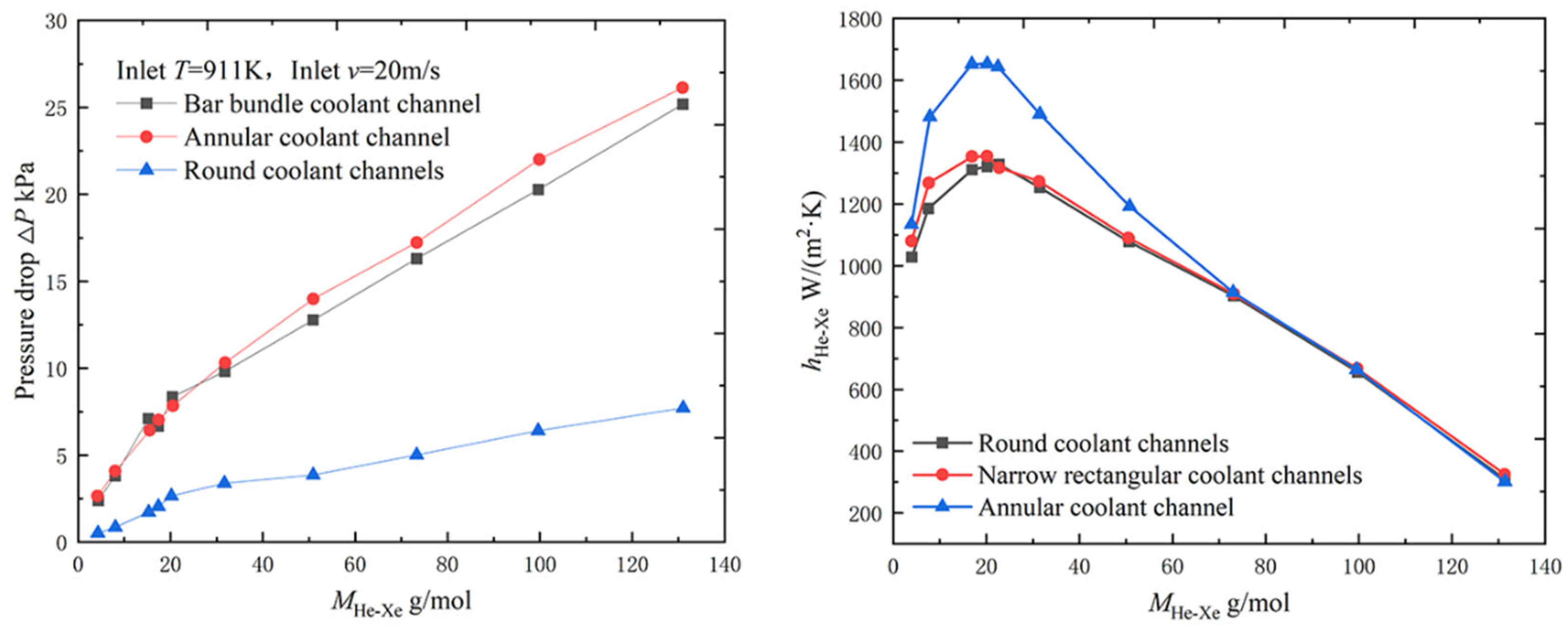
Figure 2. Pressure drop and heat transfer coefficient of the helium–xenon gas mixture in channels of different shapes [9].
Huang et al. [14] also performed a numerical simulation of the heat transfer characteristics of a helium–xenon gas mixture in different core coolant channels. The model and related parameters used in the study are shown in Figure 3 and Table 1.
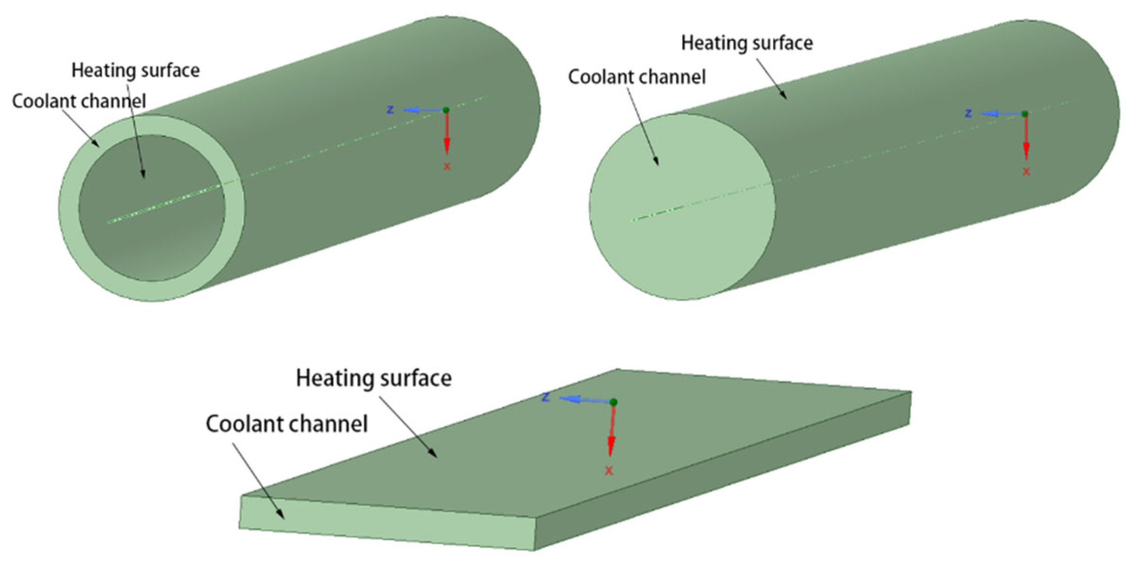
Figure 3. The model used in the numerical simulation study by Huang et al. [14].
Table 1. Parameters of the annular coolant channel model [14].
| Parameter | Value |
|---|---|
| dout/mm | 19.65 |
| δ/mm | 2.16 |
| L/mm | 1118 |
| Tin/K | 882 |
| Tout/K | 1125 |
| vin/m/s | 20 |
| Pin/MPa | 2 |
| Pout/MPa | 1.991 |
The parameters of the circular coolant channel and the narrow rectangular coolant channel are basically the same as those of the annular channel. The treatment of the different cross-sectional shapes is to control the flow area of the helium–xenon gas mixture to be the same, from which the cross-sectional dimensions of the narrow rectangular channel and the circular channel can be determined.
As shown in Figure 4, the numerical simulation study by Huang et al. [14] obtained the same conclusion, that the heat transfer coefficient of circular coolant channels is worse than that of annular coolant channels. Numerical simulation studies of narrow rectangular coolant channels resulted in heat transfer performance that was not much different from circular channels. Both were much worse than the annular coolant channels. In addition, Huang et al. [14] also calculated the equivalent diameters of these three shapes of coolant channels, as shown in Table 2. The smaller the equivalent diameter of the channel type, the larger the convective heat transfer coefficient of the helium–xenon gas mixture inside the channel, so using a channel with a smaller equivalent diameter can improve the heat transfer performance of the helium–xenon gas mixture inside the channel.
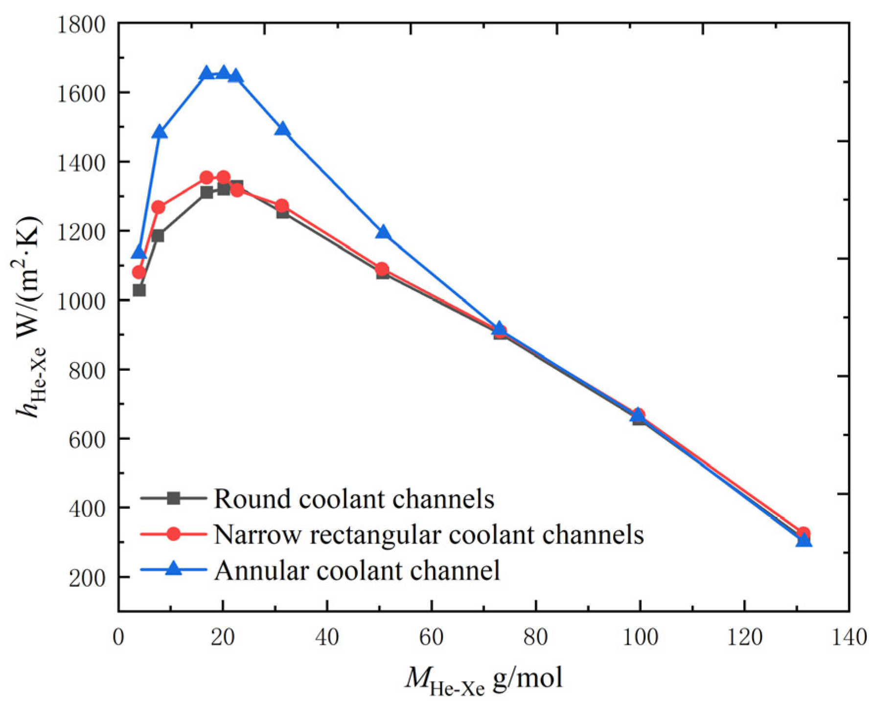
Figure 4. Variation of convective heat transfer coefficient with channel shape in the coolant channel for helium–xenon gas mixture [14].
Table 2. Comparison of the equivalent diameters (de) of the three coolant channels [14].
| Types of Coolant Channels | S/10−4 m2 | de/mm |
|---|---|---|
| Annular coolant channel | 1.48 | 4.32 |
| Circular coolant channels | 1.48 | 13.39 |
| Narrow rectangular coolant channels | 1.48 | 7.22 |
2.2. Enhanced Heat Transfer in Single Tube Channel
Chen et al. [15] investigated the effect of setting the filament winding structure inside the core circular coolant channel and its different parameters on the heat transfer characteristics of the helium–xenon gas mixture by numerical simulation. The physical model, boundary conditions, and experimental working conditions are shown in Figure 5 and Table 3 and Table 4.
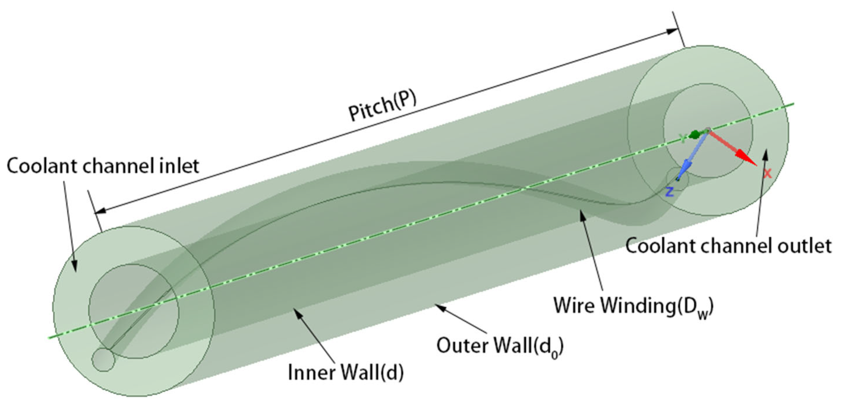
Figure 5. Physical model for numerical simulation of Chen et al. [15].
Table 3. Boundary conditions for the numerical simulation of Chen et al. [15].
| Parameter | Value |
|---|---|
| Tout/K | <1200 |
| Tw/K | <1800 |
| q/kW/m2 | 60 |
| vin/m/s | 10~27 |
| p/MPa | 1.5~2.5 |
Table 4. Working conditions of the numerical simulation of Chen et al. [15].
| Conditions | P/d | Dw/d | d0/d |
|---|---|---|---|
| Condition 1 | 30.30 | 0.3 | 1.8 |
| Condition 2 | 18.18 | 0.3 | 1.8 |
| Condition 3 | 9.09 | 0.3 | 1.8 |
| Condition 4 | 30.30 | 0.25 | 1.8 |
| Condition 5 | 30.30 | 0.15 | 1.8 |
As shown in Figure 6, with the filament winding structure, the Fanning friction factor and the frictional resistance of the helium–xenon gas mixture in the channel both increase. The increase in Reynolds number, which is also an increase in velocity, leads to a decrease in the Fanning friction factor. The larger the filament diameter and the smaller the pitch, the higher the Fanning friction factor due to the more intense disturbance. As shown in Figure 7, the filament winding structure could enhance the convective heat transfer of the helium–xenon gas mixture only under certain conditions. The larger the filament winding pitch and the larger the diameter, the worse the heat transfer characteristics. Under certain filament winding structure conditions, the presence of filament winding will lead to the deterioration of heat transfer characteristics. In the above analysis, smaller diameter and moderate pitch filament winding can fix the fuel rod with filament winding; at the same time, the flow characteristics do not deteriorate too much, and the heat transfer characteristics are slightly enhanced.
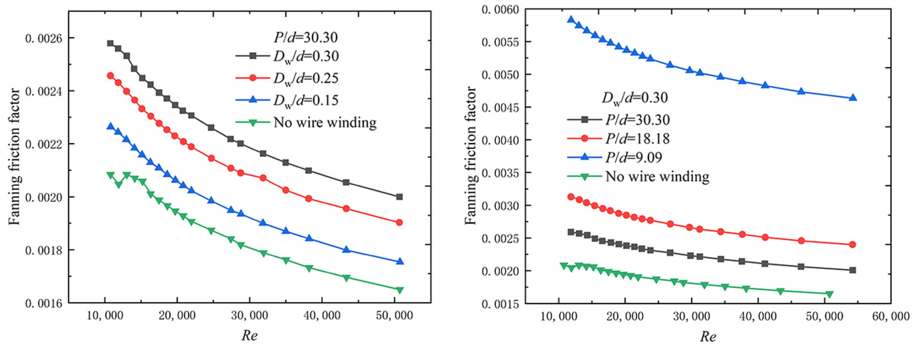
Figure 6. Variation of Fanning friction factor with filament winding parameters [15].
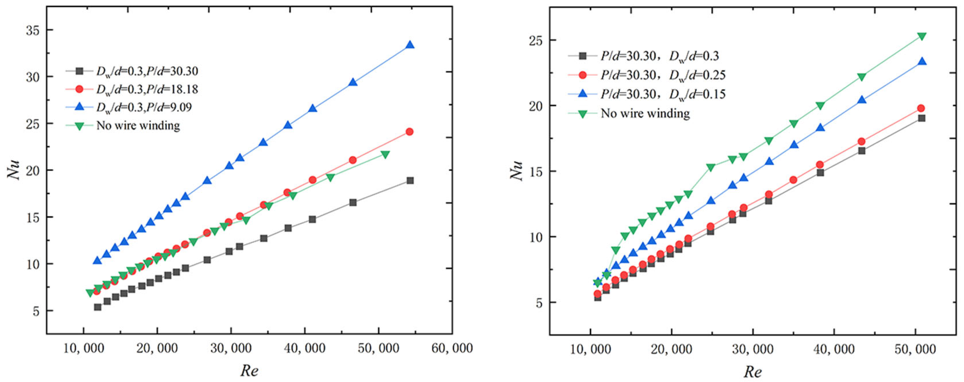
Figure 7. Variation of Nusselt number with wire winding parameters [15].
2.3. Enhanced Heat Transfer in Compact Heat Exchanger
Yang and Huo [16] studied the heat transfer characteristics of high-temperature helium–xenon gas flow in the PCHE (Printed Circuit Heat Exchanger) microchannel using numerical simulations, with a maximum working temperature of about 1000 K. The study showed that the helium–xenon gas mixture has approximately the same heat transfer characteristics in the rectangular cross-section flow channel designed for the fine engraving process and the semicircular cross-section flow channel designed for the etching process. However, the pressure drop of the workpiece in the flow channel of the fine engraving process is 40% smaller than that of the etching process. The mass of the heat return heat exchanger is also reduced by 17%, so the overall performance of the fine engraving process design is better than the etching process. The physical model, initial boundary conditions, and calculation results calculated in the literature are shown in Figure 8 and Table 5 and Table 6. In addition, the literature also investigates the effect of setting up interconnecting channels on the heat transfer characteristics, and the results show that setting up interconnecting channels does not enhance heat transfer.
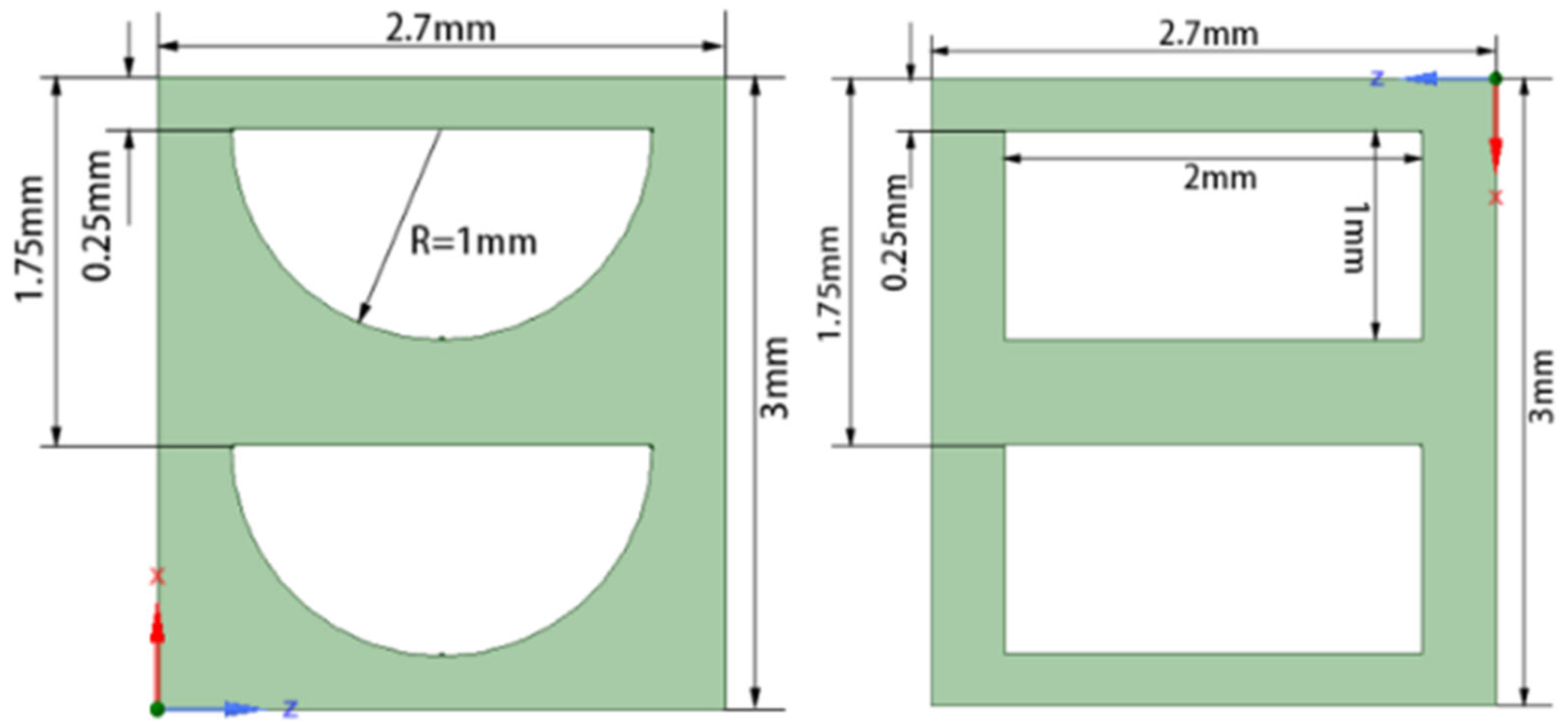
Figure 8. PCHE model for numerical simulation of the fine engraving process and etching process by Yang and Huo [16].
Table 5. Boundary conditions for single-channel heat transfer calculations by Yang and Huo [16].
| Parameter | Value |
|---|---|
| G/g/s | 0.2125 |
| Thot,in/K | 961 |
| Tcold,in/K | 516 |
| Phot,in/MPa | 1.15 |
| Pcold,in/MPa | 2.1 |
| L/mm | 390 |
Table 6. Results for single-channel heat transfer calculations by Yang and Huo [16].
| Parameter | Fine Engraving Process | Etching Process |
|---|---|---|
| Thot,out/K | 572.2 | 571.6 |
| Tcold,out/K | 905 | 905.8 |
| vhot,in/m/s | 18.3 | 23.2 |
| vcold,in/m/s | 11.0 | 14.1 |
| ΔPhot/Pa | 7508 | 12,574.8 |
| ΔPcold/Pa | 4491 | 7472 |
In summary, there are few studies on the enhanced heat transfer technology for helium–xenon gas mixtures, and the research content is not systematic and in-depth enough to provide a reference for the enhanced heat transfer technology for helium–xenon gas mixtures. In order to promote the research progress, we can refer to more literature related to heat transfer structure to obtain more research ideas [17][18][19].
References
- Wang, Z. Research on Brayton Cycle Properties of Helium-Xenon Mixed Working Fluid Based on Space Nuclear Power System. Master’s Thesis, Harbin Institute of Technology, Harbin, China, 2021.
- El-Genk, M.S.; Parlos, A.G.; McGhee, J.M.; Lapin, S.; Buden, D.; Mims, J. System design optimization for multimegawatt space nuclear power applications. J. Propuls. Power 1990, 6, 194–202.
- El-Genk, M.S. Space nuclear reactor power system concepts with static and dynamic energy conversion. Energy Convers. Manag. 2008, 49, 402–411.
- El-Genk, M.S. Deployment history and design considerations for space reactor power systems. Acta Astronaut. 2009, 64, 833–849.
- Bennett, G.; Hemler, R.; Schock, A. Space nuclear power: An overview. J. Propuls. Power 1996, 12, 901–910.
- Ren, Y. The good space electric power—Space nuclear power reactor. Nucl. Power Eng. 1993, 14, 269–273.
- Yang, Q.; Lu, H. Research and application of space nuclear reactor power. Spacecr. Eng. 1995, 4, 11–20.
- Yang, X.; Shi, L. Analysis of Helium-Xenon Mixture Property Influence on Brayton Cycle. At. Energy Sci. Technol. 2018, 52, 1407–1414.
- Yu, L. Effect of Proportion of Helium-Xenon Mixtures on the Flow and Heat Transfer Tharacteristics in the Coolant Channel of the Reactor. Master’s Thesis, Harbin Engineering University, Harbin, China, 2020.
- Long, Y. Aerodynamic Design and Performance Research on the High-Loaded Helium Compressor. Master’s Thesis, Harbin Engineering University, Harbin, China, 2012.
- Dostal, V.; Driscoll, M.J.; Hejzlar, P. A Supercritical Carbon Dioxide Cycle for Next Generation Nuclear Reactors. Mass. Inst. Technol. 2004, 154, 265–282.
- Bejan, A.; Lorente, S.; Yilbas, B.; Sahin, A. The effect of size on efficiency: Power plants and vascular designs. Int. J. Heat Mass Transf. 2011, 54, 1475–1481.
- Gnielinski, V. Neue Gleichungen für den Wärme- und den Stoffübergang in turbulent durchströmten Rohren und Kanälen. Forsch. Im Ing. A 1975, 41, 8–16.
- Huang, D.; Li, Z.; Yu, L.; He, X.; Zhao, F.; Tan, S. Influence of helium-xenon mixing ratio on flow heat transfer characteristics of reactor channels. J. Harbin Eng. Univ. 2021, 42, 745–750.
- Chen, S.; Qin, H.; Wang, C.; Zhang, Y.; Zhang, D.; Qiu, S.; Tian, W.; Su, G. Flow and Heat Transfer Characteristic of He-Xe Gas Mixture with Helical Wire Structure. At. Energy Sci. Technol. 2021, 55, 991–999.
- Yang, Y.; Huo, H. Analysis of Heat Transfer and Flow Characteristic for High Temperature Helium-xenon Gas Microchannel Regenerator. At. Energy Sci. Technol. 2018, 52, 2156–2163.
- Huang, Y.; Xiao, X.; Kang, H.; Lv, J.; Zeng, R.; Shen, J. Thermal management of polymer electrolyte membrane fuel cells: A critical review of heat transfer mechanisms, cooling approaches, and advanced cooling techniques analysis. Energy Convers. Manag. 2022, 254, 115–221.
- Chen, H.; Ruan, X.-H.; Peng, Y.-H.; Wang, Y.-L.; Yu, C.-K. Application status and prospect of spray cooling in electronics and energy conversion industries. Sustain. Energy Technol. Assess. 2022, 52, 102–181.
- Bhandari, P.; Prajapati, Y. Influences of tip clearance on flow and heat transfer characteristics of open type micro pin fin heat sink. Int. J. Therm. Sci. 2022, 179, 107–714.
More
Information
Subjects:
Energy & Fuels
Contributors
MDPI registered users' name will be linked to their SciProfiles pages. To register with us, please refer to https://encyclopedia.pub/register
:
View Times:
1.4K
Revisions:
2 times
(View History)
Update Date:
29 Dec 2022
Notice
You are not a member of the advisory board for this topic. If you want to update advisory board member profile, please contact office@encyclopedia.pub.
OK
Confirm
Only members of the Encyclopedia advisory board for this topic are allowed to note entries. Would you like to become an advisory board member of the Encyclopedia?
Yes
No
${ textCharacter }/${ maxCharacter }
Submit
Cancel
Back
Comments
${ item }
|
More
No more~
There is no comment~
${ textCharacter }/${ maxCharacter }
Submit
Cancel
${ selectedItem.replyTextCharacter }/${ selectedItem.replyMaxCharacter }
Submit
Cancel
Confirm
Are you sure to Delete?
Yes
No


