 +1 credit
| Version | Summary | Created by | Modification | Content Size | Created at | Operation |
|---|---|---|---|---|---|---|
| 1 | Eric Chappel | + 2477 word(s) | 2477 | 2020-12-16 09:11:15 |
Video Upload Options
Passive flow control regulators, also known as passive flow control or autoregulated or pressure-compensated valves, deliver, without external control and energy consumption, a constant flow rate regardless of pressure variations.
1. Introduction
Passive constant flow regulators are widely used in industry for water treatment, process water control (limiting peak flow rate), water authorities (flow limiting, boost mains pressure), centrifugal pump protection, water-saving (domestic showers, drinking fountains), irrigation, etc. These valves are compact, reliable, maintenance-free, and require no energy. Manufacturers provide passive valves dedicated to high flow rate (from a few hundred ml/min to 10,000L/min and more) and large pressure differential (from 1 bar to several hundreds of bar). More recently, microvalves have been developed for microfluidic applications, including drug delivery, flow chemistry, point-of-care tests, hydrocephalus treatment, microdialysis, etc. These passive constant flow regulators fall into two main categories: the mechanical regulators having moving parts (a membrane in silicon or elastomer, a piston, a collapsible tubing, or a flap), and non-mechanical regulators without moving parts (fixed geometry), wherein the rheological properties of the fluid are exploited to achieve a constant flow rate. Most of the regulator designs belong to the first category. The automatic adjustment of the flow rate with varying pressure conditions is therefore obtained by an automatic change of the fluidic pathway dimensions[1].
2. Working Principle
The passive constant flow regulators considered in this entry are related to microfluidics, which refers to the manipulation of fluids in channels or structures with dimensions of tens of micrometers[2]. By contrast to macroscopic fluids, viscosity is more important than inertia, and the Reynolds number (Re) that characterizes the ratio of inertial to viscous forces on the fluid is usually lower than 2000 in most microfluidic systems. The flow in such microstructures is in the laminar regime with highly predictable fluid dynamics. The estimation of the hydraulic resistances along the fluid pathway is done using the governing equations of laminar viscous fluid flow (see, e.g., References [3][4]). A constant passive flow regulator is intended to deliver a constant flow rate, 


At a given temperature, the flow rate 
|
|
(1) |

where 


|
|
(2) |
and thus:
|
|
(3) |
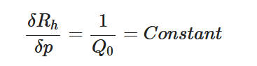
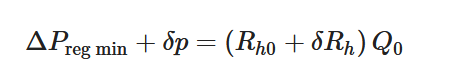
To maintain the flow rate constant in the gradient pressure range 


The change of slope in the 
The profile shown in Figure 1 is, therefore, representative of a three-stage valve:
- Stage I—low-pressure stage, with low hydraulic resistance for
- Stage II—flow regulation stage, for
- Stage III—high-pressure stage, with a low or high hydraulic resistance for

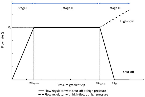
Figure 1. Ideal flow rate versus pressure gradient characteristic of a three-stage passive constant flow regulator. At low pressure (stage I), the regulator has a constant and low hydraulic resistance. In stage II, the flow is regulated at 

The passive constant flow regulator is intended to be placed into a fluidic circuit. To keep the functioning point of the device onto the plateau of the
An alternative method to maintain the flow rate at 

The combination of a pressurized reservoir and a passive constant flow regulator is recommended to avoid startup overflow and the constant decrease of the infusion rate over time as well. The infusion duration is better controlled and a flow rate error less than 
3. Working Fluid
Except for the device developed by Groisman et al.[12], almost all passive constant flow regulators dedicated to microfluidic applications were designed to work with water, cerebrospinal fluid (CSF), or other Newtonian fluids like viscous mixes of water and glycerol. In principle, the constant passive flow regulators are also compatible with gas. The modeling of a gas flow regulator can still be based on the standard continuum approach, which is still valid if no-slip boundary conditions apply, typically for Knudsen number 

In the laminar regime, a change of temperature induces a change of fluid viscosity which, in turn, leads to flow rate variability as for standard flow restrictors. Since the hydraulic resistance is proportional to the fluid dynamic viscosity 

|
|
(4) |
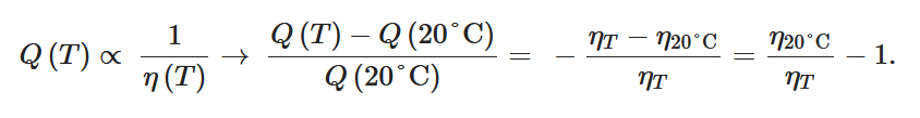
Table 1 shows, at selected temperatures, the relative flow rate error due to dynamic viscosity change. The values are derived from the empirical formula proposed by Kestin et al. for the dynamic viscosity of water in the range 


Table 1. Effect of dynamic viscosity change with temperature on relative flow rate accuracy of passive constant flow regulators. The reference temperature is
|
Temperature (°C) |
5 |
10 |
15 |
20 |
25 |
30 |
35 |
40 |
|
Water dynamic viscosity (mPa.s) |
1.520 |
1.308 |
1.139 |
1.002 |
0.890 |
0.797 |
0.719 |
0.653 |
|
Relative water flow rate error ( |
−34.1% |
−23.4% |
−12.0% |
0.0% |
12.6% |
25.7% |
39.3% |
53.5% |
 )
)4. Materials
Silicon, glass, and poly(dimethylsiloxane) (PDMS) are the most common materials in contact with the working fluid in the passive constant flow regulators reported here. Titanium[5][15] was also considered for implantable devices. Early microfluidic and Micro Total Analysis Systems (µTAS) were made in glass and silicon due to the availability of process equipment and etching recipes. Since the Whitesides’ group manufactured, in 1998, microfluidic devices in PDMS by soft lithography, PDMS became the preferred material for rapid prototyping of microchannel systems for use with biological samples [16][17][18]. Indeed, PDMS is an inexpensive, optically transparent, gas and vapor permeable, hydrophobic, relatively inert, and biocompatible polymer that, moreover, cures at low temperatures. PDMS is soft and facilitates removal from Si molds for micron-scale feature replication. The surface energy of PDMS can be tuned to increase its wettability. Also, PDMS can be sealed reversibly to itself or other materials. Last but not least, the elasticity of PDMS has been widely exploited to create membrane pumps and check valves in active microfluidic devices for cell sorting and biochemical assays[19]. PDMS was also considered to make passive flow regulators because this material enables the rapid prototyping of complex three-dimensional (3D) structures. On the other hand, PDMS presents, compared to Si and glass, some disadvantages that can preterite its use as raw material for specific microfluidic applications that require long-term stability, reproducibility, well-controlled surface chemistry, high accuracy, stiffness, high temperature, compatibility with organic solvents, or low gas/vapor permeability. Si/glass biomedical electromechanical systems (BioMEMS ) are more expensive to produce at low volume and require interconnections to the other parts of the fluidic systems. Silicon is a rigid material with a well-defined Young’s modulus by contrast to the hyperelastic PDMS, whose mechanical properties are highly dependent on its degree of cross-linking and stretching. Si membranes exhibit a highly reproducible displacement and no fatigue, and the electronic properties of silicon enable the smart integration of reliable sensors[20]. Also, the negative charge surface of glass and silicon support electroosmotic flow (EOF).
5. Modeling
The modeling of the passive constant flow regulator can be based on analytical models[5][21][22], but in a general way, 3D simulations using finite element methods are required to model the fluid–structure interactions (FSI) and the nonlinear behavior of membranes or flaps under large deformations. Numerical simulations are also useful to investigate the impact of machining tolerances on flow rate accuracy[8]. Specific tools using a genetic algorithm have been made to increase the yield in production by design optimization. This method was used to design a regulator with a flexible Si membrane that deflects against pillars. In addition to standard machining tolerances, other non-idealities have been introduced into the model, like wafer misalignment or valve tilt (due to particle contamination for instance) to increase the design robustness[21][23].
A passive flow regulator is usually part of a complex microfluidic system. In addition to these quasi-static analyses of the fluid flow in fixed pressure conditions, further simulations shall be carried out to calculate the fluid dynamics in a system that can include microchannels, check valves, micropumps, pressure sources, etc. As a passive flow regulator induces nonlinear effects, the equations governing the fluidic behavior of such systems generally have no analytical solutions. A classical approach consists of building an electrical equivalent network based on a subdivision of the system into lumped elements and the analogy between fluidic, mechanical, and electrical parameters[24][25]. The impedance of each element is estimated beforehand. For a passive flow regulator with an integrated check-valve, its electrical analog is a diode in series with a variable resistor. The analysis of the dynamics of complex systems can then be carried out very quickly with an electrical simulation tool. This method was chosen to simulate the dynamics of a hydrocephalus shunt comprising a passive flow regulator to divert CSF from the brain ventricles to the peritoneal cavity[26]. The ventricles are equivalent to a constant current source that produces about 20 mL of CSF every hour. The numerical model allowed the determination of the time evolution of intracranial pressure during patient postural changes, changes in the CSF formation rate, oscillations due to the vasogenic system, etc., together with a direct comparison with other shunt designs. Dynamic simulations based on electrical equivalent networks are particularly useful during the design phase to determine the behavior of the passive flow regulator. For a complex system such as the hydrocephalus flow control valve, the model can be further refined by the introduction of experimental data[27].
6. Recent trends and future prospects
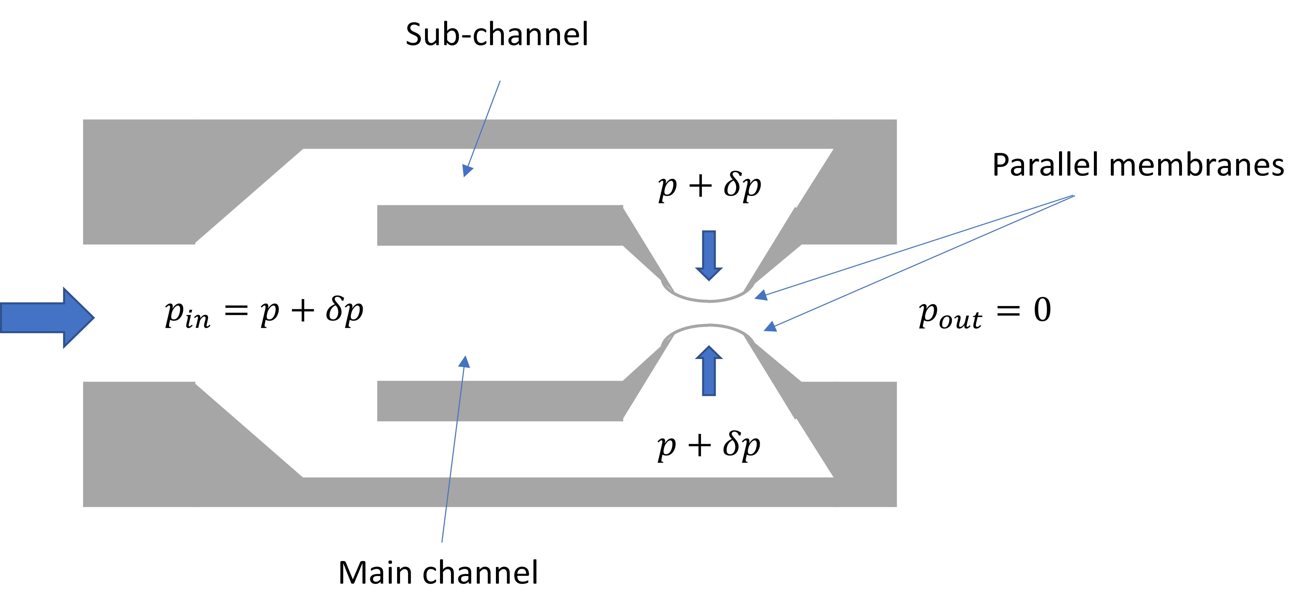
Active fluid control poses numerous problems of integration and miniaturization, and the development of microvalves and micropumps, which are two important building blocks of a microfluidic platform, was stimulated by recent advances in lab-on-a-chip for diagnostics applications, drug delivery, flow chemistry, point-of-care testing, etc. Compared to active microvalves[28], passive constant flow control valves provide a simpler way to regulate fluid flows without external control and energy consumption. A comprehensive design review of the passive constant flow regulators developed over the last three decades can be found in Reference[1]. The designs of typical passive constant flow regulators made using MEMS technology and PDMS are shown in Figures 2 and 3 respectively.
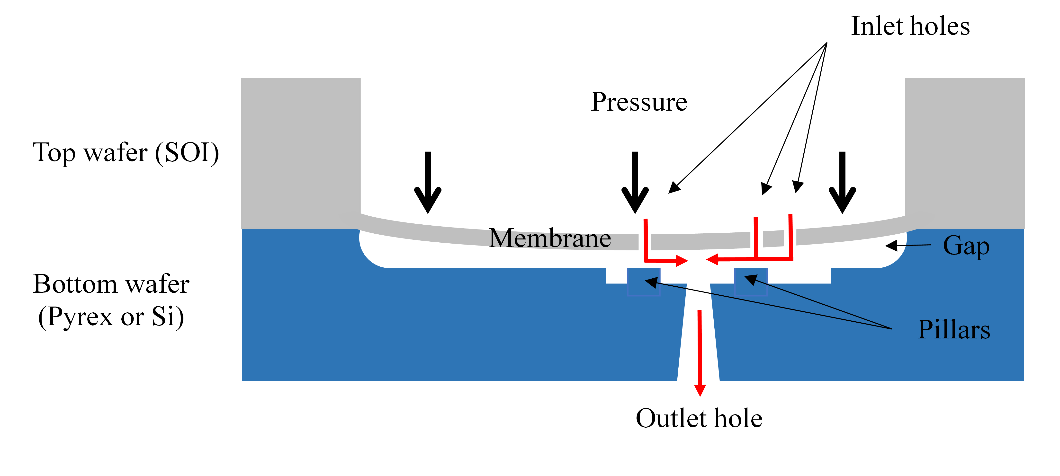
Figure 2. Cross-section of a passive flow regulator with a top Silicon-On-Insulator (SOI) wafer (membrane) and a bottom wafer (substrate) made of Pyrex or silicon (Si). The fluid flows through the inlet holes of the membrane, the radial diffuser (annular restriction between the membrane and the pillar), and the outlet hole of the substrate. As the pressure increases, the deflection of the membrane induces an increase in the hydraulic resistance of the radial diffuser to keep the flow rate constant. The flow direction is indicated by red arrows[21].
The modeling, the fabrication methods, and the resulting performance of these passive microvalves have been constantly improved. Table 2 summarizes the principal pros and cons of each category of passive flow regulators.
Table 2: Comparative table of the different categories of passive constant flow regulators
|
|
Pressure Range |
Flow Rate Range |
Accuracy/Reproducibility |
Connectivity |
Fabrication Cost |
Prototyping Complexity |
Aqueous Solution |
|
MECHANICAL |
|
|
|
|
|
|
|
|
Si membrane(s) |
Very large |
Very large |
High/Very High |
Medium |
Low*/High |
High |
Yes |
|
Elastomeric membrane(s) |
Large |
Very large |
High/Medium** |
High |
Low/Medium |
Low/Medium |
Yes |
|
Tube with lateral aperture |
Small |
Small |
Low/Low |
Medium |
Low |
Low |
Yes |
|
Piston |
Large |
Large |
High/Medium** |
Medium |
Medium |
Medium |
Yes |
|
Flap |
Large |
Large |
High/Medium** |
High |
Low/Medium |
Low/Medium |
Yes |
|
NON-MECHANICAL |
|
|
|
|
|
|
|
|
Rheological |
Small |
Small |
Low/Medium** |
High |
Low |
Low |
No |
*At large volumes only; ** Estimation.
Hysteresis was not included in this comparative table because this effect should be better characterized. Besides, considerations relative to the manufacturing reproducibility of the passive flow regulators made in PDMS are still speculative and have yet to be demonstrated. Recent advances in the development of these devices are promising but Table 2 also suggests that there is still room for further developing the technology and designing passive constant flow regulators that ideally combine the reliability and performance of MEMS-based valves with the ease of production and the large integration capability of their PDMS counterparts.
References
- Eric Chappel; A Review of Passive Constant Flow Regulators for Microfluidic Applications. Applied Sciences 2020, 10, 8858, 10.3390/app10248858.
- George M. Whitesides; The origins and the future of microfluidics. Nature Cell Biology 2006, 442, 368-373, 10.1038/nature05058.
- Frank M. White. Viscous Fluid Flow; McGraw-Hill: New York, NY, USA, 1991; pp. 114-125.
- Jonathan Cottet; Philippe Renaud. Chapter 1 - Introduction to Microfluidics. In book: Drug Delivery Devices and Therapeutic Systems; Chappel, E., Eds.; Academic Press: New-York, NY, USA, 2020; pp. 3-17.
- Eric Chappel; Design and characterization of a passive flow control valve dedicated to the hydrocephalus treatment. Cogent Engineering 2016, 3, 1247612, 10.1080/23311916.2016.1247612.
- Newton Paes; A new self-adjusting flow-regulating device for shunting of CSF. Child's Nervous System 1996, 12, 619-625, 10.1007/bf00261658.
- Eric Chappel. Chapter 7 - Implantable drug delivery devices. In book: Drug delivery systems and therapeutic applications; Chappel, E., Eds.; Academic Press: New-York, NY, USA, 2020; pp. 129-156.
- Dimitry Dumont-Fillon; Damien Lamaison; Eric Chappel; Design and Characterization of 3-Stack MEMS-Based Passive Flow Regulators for Implantable and Ambulatory Infusion Pumps. The Critical Role of Environment in Fatigue Damage Accumulation in Deep-Reactive Ion-Etched Single-Crystal Silicon Structural Films 2020, 29, 170-181, 10.1109/jmems.2019.2962107.
- Elena A. Skryabina; Teresa S. Dunn; Disposable infusion pumps. American Journal of Health-System Pharmacy 2006, 63, 1260-1268, 10.2146/ajhp050408.
- David F. Capes; Donna Asiimwe; Performance of selected flow-restricting infusion devices.. American Journal of Health-System Pharmacy 1998, 55, 351-359, 10.1093/ajhp/55.4.351.
- Brian M. Ilfeld; Timothy E. Morey; F. Kayser Enneking; The Delivery Rate Accuracy of Portable Infusion Pumps Used for Continuous Regional Analgesia. Anesthesia & Analgesia 2002, 95, 1331-1336, 10.1097/00000539-200211000-00043.
- Alex Groisman; Markus Enzelberger; Stephen R. Quake; Microfluidic Memory and Control Devices. Science 2003, 300, 955-958, 10.1126/science.1083694.
- Subrata Roy; Reni Raju; Helen F. Chuang; B.A. Cruden; M. Meyyappan; Modeling gas flow through microchannels and nanopores. Journal of Applied Physics 2003, 93, 4870-4879, 10.1063/1.1559936.
- Joseph Kestin; Mordechai Sokolov; William A. Wakeham; Viscosity of liquid water in the range −8 °C to 150 °C. Journal of Physical and Chemical Reference Data 1978, 7, 941-948, 10.1063/1.555581.
- C. Amacker; Y.-S Leung Ki; V. Pasquier; C. Madore; M. Haller; P. Renaud; N. White; Passive micro-flow regulator for drug delivery system. In Proceedings of the Eurosensors XII Conference, Southampton, UK. 1998, 1-2, 591-594.
- David C. Duffy; J. Cooper McDonald; Olivier J. A. Schueller; George M. Whitesides; Rapid Prototyping of Microfluidic Systems in Poly(dimethylsiloxane). Analytical Chemistry 1998, 70, 4974-4984, 10.1021/ac980656z.
- J. Cooper McDonald; David C. Duffy; Janelle R. Anderson; Daniel T. Chiu; Hongkai Wu; Olivier J. A. Schueller; George M. Whitesides; Fabrication of microfluidic systems in poly(dimethylsiloxane). ELECTROPHORESIS 2000, 21, 27-40, 10.1002/(sici)1522-2683(20000101)21:1<27::aid-elps27>3.0.co;2-c.
- Eric K. Sackmann; Anna L. Fulton; David J. Beebe; The present and future role of microfluidics in biomedical research. Nature Cell Biology 2014, 507, 181-189, 10.1038/nature13118.
- Stephen Quake; From Micro- to Nanofabrication with Soft Materials. Science 2000, 290, 1536-1540, 10.1126/science.290.5496.1536.
- Kurt E Petersen; Silicon as a mechanical material. Proceedings of the IEEE 1982, 70, 420-457, 10.1109/proc.1982.12331.
- Laurent Cornaggia; Luc Conti; Mélanie Hannebelle; Stephan Gamper; Dimitry Dumont-Fillon; Harald Van Lintel; Philippe Renaud; Eric Chappel; Zhongmin Jin; Passive flow control valve for protein delivery. Cogent Engineering 2017, 4, 1413923, 10.1080/23311916.2017.1413923.
- Ayobami Elisha Oseyemi; Xinjie Zhang; Theoretical modeling of the behavior of a parallel membrane passive flow regulator. Sensors and Actuators A: Physical 2020, 315, 112310, 10.1016/j.sna.2020.112310.
- Dimitry Dumont-Fillon; Mélanie Hannebelle; Harald Van Lintel; Eric Chappel; Design of a Passive Flow Regulator Using a Genetic Algorithm. Procedia Engineering 2016, 168, 1016-1019, 10.1016/j.proeng.2016.11.329.
- Roland Zengerle; Martin Richter; Simulation of microfluid systems. Journal of Micromechanics and Microengineering 1994, 4, 192-204, 10.1088/0960-1317/4/4/004.
- Tarik Bourouina; Jean-Paul Grandchamp; Modeling micropumps with electrical equivalent networks. Journal of Micromechanics and Microengineering 1996, 6, 398-404, 10.1088/0960-1317/6/4/006.
- Eric Chappel; Mélanie Hannebelle; Laurent Cornaggia; Dimitry Dumont-Fillon; Shahan Momjian; Duncan Shepherd; Hybrid hydrodynamic characteristic for hydrocephalus valve: A numerical investigation using electrical equivalent networks. Cogent Engineering 2017, 4, 1415103, 10.1080/23311916.2017.1415103.
- Nikolaos Tachatos; Eric Chappel; Dimitry Dumont-Fillon; Mirko Meboldt; Marianne Schmid Daners; Posture related in-vitro characterization of a flow regulated MEMS CSF valve. Biomedical Microdevices 2020, 22, 1-12, 10.1007/s10544-020-0471-0.
- Kwang W Oh; Chong H Ahn; A review of microvalves. Journal of Micromechanics and Microengineering 2006, 16, R13-R39, 10.1088/0960-1317/16/5/r01.
- Il Doh; Young-Ho Cho; Passive flow-rate regulators using pressure-dependent autonomous deflection of parallel membrane valves. Lab on a Chip 2009, 9, 2070-2075, 10.1039/b821524c.

