 +1 credit
| Version | Summary | Created by | Modification | Content Size | Created at | Operation |
|---|---|---|---|---|---|---|
| 1 | Susana Estefany De León- Aldaco | -- | 1559 | 2022-12-13 17:31:47 | | | |
| 2 | Peter Tang | Meta information modification | 1559 | 2022-12-14 07:22:29 | | | | |
| 3 | Peter Tang | Meta information modification | 1559 | 2022-12-15 07:18:25 | | |
Video Upload Options
There are some phenomena that affect electric vehicle performance. One of those phenomena is the torque ripple of electric motors, which interferes with traction and the suspension system (causing vibration that stresses this system), and it can also introduce electric current harmonics into the battery, reducing its life, since torque ripple is partly a consequence of non-sinusoidal back EMF. For those reasons this is a topic worth investigating. The torque ripple of permanent magnets (PM) motors can be reduced in design or through control.
1. Introduction
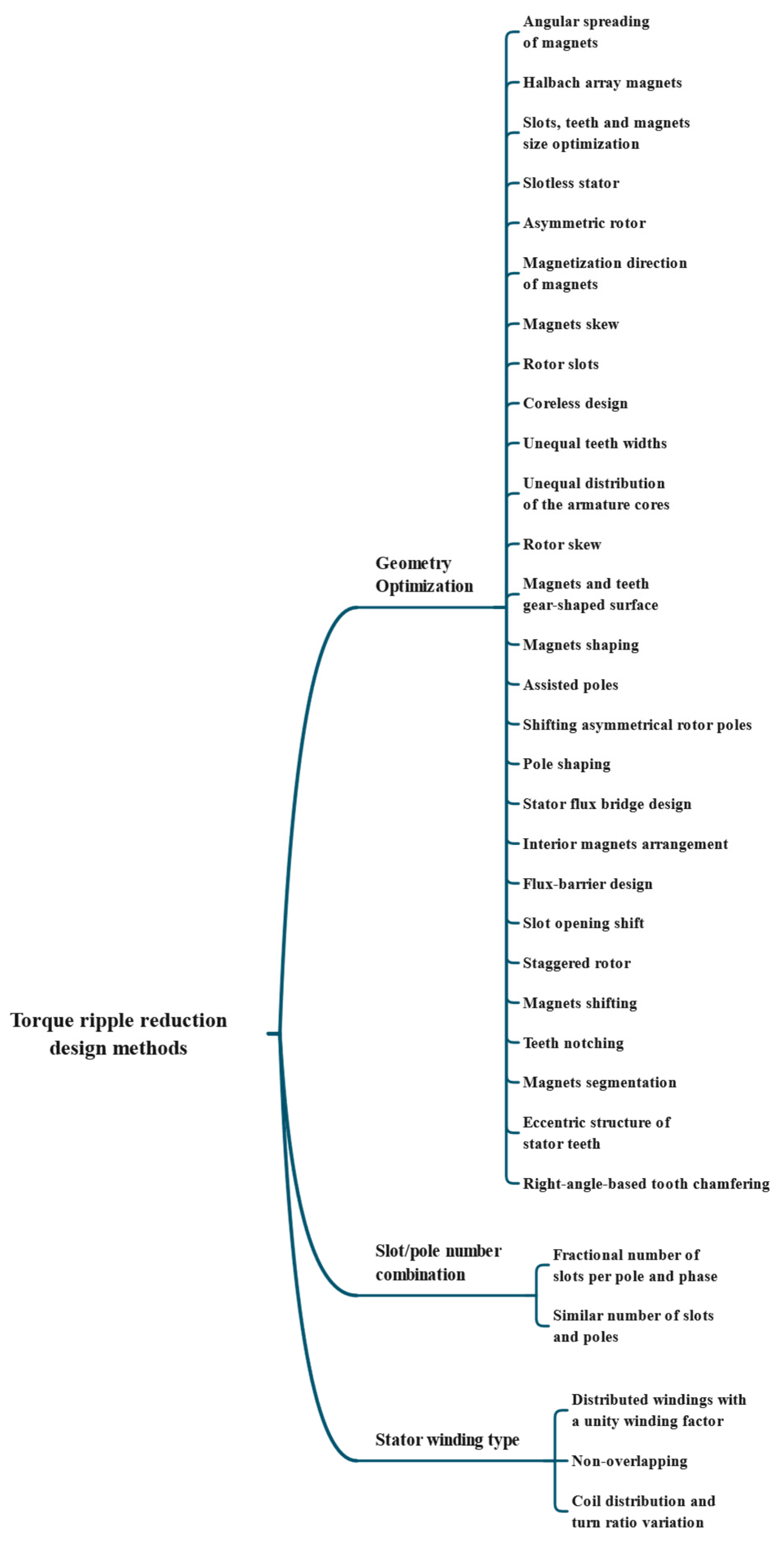
2. Torque Ripple Reduction Design Methods
|
Reference |
Machine Topology |
Design Technique |
Torque Ripple Reduction Ratio (%) |
Slot/Pole Number |
Rated Power (W) |
Average Torque (Nm) |
Rated Speed (rpm) |
|---|---|---|---|---|---|---|---|
|
High Torque Density and Low Torque Ripple-Shaped Magnet Machines Using Sinusoidal Plus Third Harmonic-Shaped Magnets [8] |
Radial flux, surface permanent magnets |
Magnets shaping |
88.50 |
24/8 |
54 |
184 |
2800 |
|
A Dual Notched Design of Radial-Flux Permanent Magnet Motors with Low Cogging Torque and Rare Earth Material [9] |
Radial flux, surface permanent magnets |
Gear-shaping the surfaces of magnets and teeth |
62.8 |
18/12 |
80 |
− |
10,000 |
|
Torque Ripple Reduction of Saliency-Based Sensorless Drive Concentrated Winding IPMSM Using Novel Flux Barrier [10] |
Saliency-based, interior permanent magnets |
Flux barrier design |
28 |
9/6 |
5500 |
45 |
1750 |
|
Reduction of Torque Ripple in Consequent Pole Permanent Magnet Machines Using Staggered Rotor [11] |
Consequent-Pole permanent magnet motor |
Staggered rotor design |
60 |
9/6 |
− |
2.13 |
1500 |
|
Optimal Design to Reduce Torque Ripple of IPM Motor with Radial-Based Function Meta-Model Considering Design Sensitivity Analysis [12] |
Radial flux, interior permanent magnets |
Slots, teeth, and magnet size optimization |
58 |
48/8 |
50,000 |
400 |
1200 |
|
Permanent Magnet Motor Design for Satellite Attitude Control With High Torque Density and Low Torque Ripple [13] |
Radial flux, dual rotor |
Slotless windings and Halbach array magnets |
67 |
9/8 |
11.5 |
32.15 m |
6000 |
|
Optimization of Torque Ripples in an Interior Permanent Magnet Synchronous Motor Based on the Orthogonal Experimental Method and MIGA and RBF Neural Networks [14] |
Radial flux, interior permanent magnets |
Stator, rotor, and magnets sizes optimization |
84 |
24/8 |
5010 |
4.2 |
− |
|
Asymmetric Rotor Design of IPMSM for Vibration Reduction Under Certain Load Condition [15] |
Radial flux, interior permanent magnets |
Asymmetric rotor shape |
33.10 |
12/8 |
5000 |
24 |
2000 |
|
Ferrite PM Optimization of SPM BLDC Motor for Oil-Pump Applications, According to Magnetization Direction [16] |
Brushless DC |
Parallel magnetization direction of permanent magnets |
69.20 |
12/8 |
126 |
0.33 |
3200 |
|
Design and Analysis of Halbach Ironless Flywheel BLDC Motor/Generators [17] |
Brushless DC, outer rotor |
Halbach array magnets |
20 |
6/8 |
− |
800 m |
40,000 |
|
Design Optimisation of an Outer Rotor Permanent Magnet Synchronous Hub Motor for a Low-Speed Campus Patrol EV [18] |
Radial flux, outer rotor |
Similar number of slots and poles |
29 |
51/50 |
− |
94.5 |
600 |
|
Effect Comparison of Zigzag Skew PM Pole and Straight Skew Slot for Vibration Mitigation of PM Brush DC Motors [19] |
Brush DC |
Zigzag skewed magnets |
37.5 |
24/4 |
800 |
2.147 |
2700 |
|
Analytical Prediction and Optimization of Cogging Torque in Surface-Mounted Permanent Magnet Machines With Modified Particle Swarm Optimization [20] |
Radial flux, surface permanent magnets |
Air-gap length and magnet thickness optimization, fractional slot-pole number, and parallel magnetization of permanent magnets |
92.48 |
12/8 |
− |
− |
− |
|
Material-Efficient Permanent Magnet Shape for Torque Pulsation Minimization in SPM Motors for Automotive Applications [21] |
Radial flux, surface permanent magnets |
Magnets shaping and skewing |
86.1 |
6/4 |
264.4 |
0.5053 |
1000 |
|
Modeling of Novel Permanent Magnet Pole Shape SPM Motor for Reducing Torque Pulsation [22] |
Radial flux, surface permanent magnets |
Magnets shaping |
72.08 |
6/4 |
340.48 |
0.6503 |
5000 |
|
Reduction of Torque Ripple Caused by Slot Harmonics in FSCW Spoke-Type FPM Motors by Assisted Poles [23] |
Spoke-type |
Fractional slot concentrated winding and assisted poles |
40 |
12/10 |
− |
6.5 |
1500 |
|
Torque Ripple Reduction in Five-Phase IPM Motors by Lowering Interactional MMF [24] |
Radial flux, interior permanent magnets |
Asymmetrical rotor poles shifting |
− |
40/8 |
− |
10.45 |
1500 |
|
Torque Ripple Reduction of a Salient Pole Permanent Magnet Synchronous Machine, with an Advanced Step-Skewed Rotor Design [25] |
Salient-pole, surface permanent magnets |
Eccentric airgap, advanced step-skewed rotor, and pole shoes skewing |
91 |
36/4 |
1500 |
10.52 |
1500 |
|
Efficient Utilization of Rare Earth Permanent-Magnet Materials and Torque Ripple Reduction in Interior Permanent-Magnet Machines [26] |
Radial flux, interior permanent magnets |
Rotor made by segments arranged in the axial direction, and pole shaping |
50 |
48/8 |
68,000 |
210 |
3080 |
|
Investigation of Short Permanent Magnet and Stator Flux Bridge Effects on Cogging Torque Mitigation in FSPM Machines [27] |
Flux-switching |
Short magnet and stator flux bridge |
32.70 |
12/10 |
500 |
3.05 |
1500 |
|
Reduction of Torque Ripple in Inset Permanent Magnet Synchronous Motor by Magnets Shifting [28] |
Radial flux, interior permanent magnets |
Magnets shifting |
28 |
48/8 |
− |
244 |
− |
− Not reported.
2.1. General Classification
2.2. Slot/Pole Number Combination
2.3. Stator Winding Type
References
- Mahmoudi, A.; Rahim, N.A.; Ping, H.W. Axial-flux permanent-magnet motor design for electric vehicle direct drive using sizing equation and finite element analysis. Prog. Electromagn. Res. 2012, 122, 467–496.
- Hanselman, D.C. Brushless Permanent Magnet Motor Design; The Writers’ Collective: Cranston, RI, USA, 2003.
- Zhu, X.; Fan, D.; Xiang, Z.; Quan, L.; Hua, W.; Cheng, M. Systematic multi-level optimization design and dynamic control of less-rare-earth hybrid permanent magnet motor for all-climatic electric vehicles. Appl. Energy 2019, 253, 113549.
- Feng, S.; Magee, C.L. Technological development of key domains in electric vehicles: Improvement rates, technology trajectories and key assignees. Appl. Energy 2020, 260, 114264.
- Long, G.; Ding, F.; Zhang, N.; Zhang, J.; Qin, A. Regenerative active suspension system with residual energy for in-wheel motor driven electric vehicle. Appl. Energy 2020, 260, 114180.
- Uddin, K.; Moore, A.D.; Barai, A.; Marco, J. The effects of high frequency current ripple on electric vehicle battery performance. Appl. Energy 2016, 178, 142–154.
- Lopez, C.A.; Jensen, W.R.; Hayslett, S.; Foster, S.N.; Strangas, E.G. A Review of Control Methods for PMSM Torque Ripple Reduction. In Proceedings of the 2018 XIII International Conference on Electrical Machines (ICEM), Alexandroupoli, Greece, 3–6 September 2018; pp. 521–526.
- Du, Z.S.; Lipo, T.A. High Torque Density and Low Torque Ripple Shaped-Magnet Machines Using Sinusoidal Plus Third Harmonic Shaped Magnets. IEEE Trans. Ind. Appl. 2019, 55, 2601–2610.
- Yu, H.; Yu, B.; Yu, J.; Lin, C. A Dual Notched Design of Radial-Flux Permanent Magnet Motors with Low Cogging Torque and Rare Earth Material. IEEE Trans. Magn. 2014, 50, 2329139.
- Kano, Y. Torque Ripple Reduction of Saliency-Based Sensorless Drive Concentrated-Winding IPMSM Using Novel Flux Barrier. IEEE Trans. Ind. Appl. 2015, 51, 2905–2916.
- Li, J.; Wang, K.; Li, F. Reduction of Torque Ripple in Consequent-Pole Permanent Magnet Machines Using Staggered Rotor. IEEE Trans. Energy Convers. 2019, 34, 643–651.
- Cho, S.; Lee, D.-C.; Hwang, J.; Kim, K.; Jang, G.U.; Bae, D.-S.; Mok, H.S.; Kim, C.-W. Optimal design to reduce torque ripple of IPM motor with radial based function meta-model considering design sensitivity analysis. J. Mech. Sci. Technol. 2019, 33, 3955–3961.
- Chou, P.-H.; Yang, S.-C.; Jhong, C.-J.; Huang, J.-I.; Chen, J.-Y. Permanent Magnet Motor Design for Satellite Attitude Control with High Torque Density and Low Torque Ripple. IEEE Access 2020, 8, 48587–48598.
- Jinshun, H.; Shuangfu, S.; Yiyong, Y.; Yang, W.; Wenjie, W.; Chen, X. Optimization of Torque Ripples in an Interior Permanent Magnet Synchronous Motor Based on the Orthogonal Experimental Method and MIGA and RBF Neural Networks. IEEE Access 2020, 8, 27202–27209.
- Jung, Y.-H.; Park, M.-R.; Lim, M.-S. Asymmetric Rotor Design of IPMSM for Vibration Reduction under Certain Load Condition. IEEE Trans. Energy Convers. 2020, 35, 928–937.
- Liu, H.-C.; Kim, H.; Jang, H.; Jang, I.-S.; Lee, J. Ferrite PM Optimization of SPM BLDC Motor for Oil-Pump Applications According to Magnetization Direction. IEEE Trans. Appl. Supercond. 2020, 30, 2977615.
- Liu, K.; Yin, M.; Hua, W.; Ma, Z.; Lin, M.; Kong, Y. Design and Analysis of Halbach Ironless Flywheel BLDC Motor/Generators. IEEE Trans. Magn. 2018, 54, 2833958.
- Shi, Z.; Sun, X.; Cai, Y.; Xiang, T.; Chen, L. Design optimisation of an outer-rotor permanent magnet synchronous hub motor for a low-speed campus patrol EV. IET Electr. Power Appl. 2020, 14, 2111–2118.
- Wang, S.; Hong, J.; Sun, Y.; Cao, H. Effect Comparison of Zigzag Skew PM Pole and Straight Skew Slot for Vibration Mitigation of PM Brush DC Motors. IEEE Trans. Ind. Electron. 2020, 67, 4752–4761.
- Xue, Z.-Q.; Li, H.-S.; Zhou, Y.; Ren, N.-N.; Wen, W. Analytical Prediction and Optimization of Cogging Torque in Surface-Mounted Permanent Magnet Machines with Modified Particle Swarm Optimization. IEEE Trans. Ind. Electron. 2017, 64, 9795–9805.
- Zhao, W.; Lipo, T.A.; Kwon, B.-i. Material-Efficient Permanent-Magnet Shape for Torque Pulsation Minimization in SPM Motors for Automotive Applications. IEEE Trans. Ind. Electron. 2014, 61, 5779–5787.
- Shah, S.Q.A.; Lipo, T.A.; Kwon, B.-i. Modeling of Novel Permanent Magnet Pole Shape SPM Motor for Reducing Torque Pulsation. IEEE Trans. Magn. 2012, 48, 4626–4629.
- Chen, Q.; Xu, G.; Liu, G.; Zhai, F.; Eduku, S. Reduction of Torque Ripple Caused by Slot Harmonics in FSCW Spoke-Type FPM Motors by Assisted Poles. IEEE Trans. Ind. Electron. 2020, 67, 9613–9622.
- Chen, Q.; Xu, G.; Liu, G.; Zhao, W.; Liu, L.; Zhipeng, L. Torque Ripple Reduction in Five-Phase IPM Motors by Lowering Interactional MMF. IEEE Trans. Ind. Electron. 2018, 65, 8520–8531.
- Chen, W.; Ma, J.; Wu, G.-c.; Fang, Y. Torque Ripple Reduction of a Salient-Pole Permanent Magnet Synchronous Machine with an Advanced Step-Skewed Rotor Design. IEEE Access 2020, 8, 118989–118999.
- Du, Z.S.; Lipo, T.A. Efficient Utilization of Rare Earth Permanent-Magnet Materials and Torque Ripple Reduction in Interior Permanent-Magnet Machines. IEEE Trans. Ind. Appl. 2017, 53, 3485–3495.
- Gan, C.; Wu, J.; Shen, M.; Kong, W.; Hu, Y.; Cao, W. Investigation of Short Permanent Magnet and Stator Flux Bridge Effects on Cogging Torque Mitigation in FSPM Machines. IEEE Trans. Energy Convers. 2018, 33, 845–855.
- Liu, G.; Du, X.; Zhao, W.; Chen, Q. Reduction of Torque Ripple in Inset Permanent Magnet Synchronous Motor by Magnets Shifting. IEEE Trans. Magn. 2017, 53, 2620422.

