 +1 credit
| Version | Summary | Created by | Modification | Content Size | Created at | Operation |
|---|---|---|---|---|---|---|
| 1 | Sirius Huang | -- | 3336 | 2022-11-30 01:37:20 | | | |
| 2 | Sirius Huang | + 122 word(s) | 3458 | 2022-12-06 08:08:04 | | |
Video Upload Options
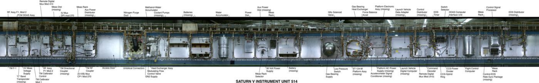
The Saturn V Instrument Unit is a ring-shaped structure fitted to the top of the Saturn V rocket's third stage (S-IVB) and the Saturn IB's second stage (also an S-IVB). It was immediately below the SLA (Spacecraft/Lunar Module Adapter) panels that contained the Lunar Module. The Instrument Unit contains the guidance system for the Saturn V rocket. Some of the electronics contained within the Instrument Unit are a digital computer, analog flight control computer, emergency detection system, inertial guidance platform, control accelerometers and control rate gyros. The instrument unit (IU) for Saturn V was designed by NASA at Marshall Space Flight Center (MSFC) and was developed from the Saturn I IU. NASA's contractor to construct the Saturn V Instrument Unit was International Business Machines (IBM). One of the unused Instrument Units is currently on display at the Steven F. Udvar-Hazy Center in Chantilly, Virginia. The plaque for the Unit has the following inscription: The Saturn V rocket, which sent astronauts to the Moon, used inertial guidance, a self-contained system that guided the rocket's trajectory. The rocket booster had a guidance system separate from those on the command and lunar modules. It was contained in an instrument unit like this one, a ring located between the rocket's third stage and the command and lunar modules. The ring contained the basic guidance system components—a stable platform, accelerometers, a digital computer, and control electronics—as well as radar, telemetry, and other units. The instrument unit's stable platform was based on an experimental unit for the German V-2 rocket of World War II. The Bendix Corporation produced the platform, while IBM designed and built the unit's digital computer.
1. Instrument Unit Specifications
- Diameter: 260 inches (6.6 m)
- Height: 36 inches (914 mm)
- Weight at launch: ~4,400 lb (1996 kg)
2. Mission History
There was no Instrument Unit for Saturn I Block I boosters (SA-1 to SA-4). Guidance and control equipment was carried in canisters on top of the S-I first stage, and included the ST-90 stabilized platform, made by Ford Instrument Company and used in the Jupiter missile.[1]
The IU made its debut with SA-5, the first Saturn I Block II launch. The first version of the IU was 154 inches (3,900 mm) in diameter and 58 inches (1,500 mm) high, and was both designed and built by MSFC. Guidance, telemetry, tracking and power components were contained in four pressurized, cylindrical containers attached like spokes to a central hub.[2]
MSFC flew version 2 of the IU on SA-8, 9 and 10. Version 2 was the same diameter as version 1, but only 34 inches (860 mm) high. Instead of pressurized containers, the components were hung on the inside of the cylindrical wall, achieving a reduction in weight.[3]
The last version, number 3, was 260 inches (6,600 mm) in diameter and 36 inches (910 mm) tall. It was designed by MSFC but manufactured by IBM in their factory at Huntsville, and flew on all Saturn IB and Saturn V launches. This is the version that is on display in Washington, Huntsville, Houston, and the Apollo/Saturn V Center.
| Program | Vehicle | Mission | Launch date | Pad | IU version |
|---|---|---|---|---|---|
| Saturn I | SA-1 | SA-1 | 27 Oct 1961 | 34 | - |
| Saturn I | SA-2 | SA-2 | 25 Apr 1962 | 34 | - |
| Saturn I | SA-3 | SA-3 | 16 Nov 1962 | 34 | - |
| Saturn I | SA-4 | SA-4 | 28 Mar 1963 | 34 | - |
| Saturn I | SA-5 | SA-5 | 29 Jan 1964 | 37B | 1 |
| Saturn I | SA-6 | AS-101 | 28 May 1964 | 37B | 1 |
| Saturn I | SA-7 | AS-102 | 18 Sep 1964 | 37B | 1 |
| Saturn I | SA-9 | AS-103 | 16 Feb 1965 | 37B | 2 |
| Saturn I | SA-8 | AS-104 | 25 May 1965 | 37B | 2 |
| Saturn I | SA-10 | AS-105 | 30 Jul 1965 | 37B | 2 |
| Saturn IB | SA-201 | AS-201 | 26 Feb 1966 | 34 | 3 |
| Saturn IB | SA-203 | AS-203 | 5 Jul 1966 | 37B | 3 |
| Saturn IB | SA-202 | AS-202 | 25 Aug 1966 | 34 | 3 |
| Saturn V | SA-501 | Apollo 4 | 9 Nov 1967 | 39A | 3 |
| Saturn IB | SA-204 | Apollo 5 | 22 Jan 1968 | 37B | 3 |
| Saturn V | SA-502 | Apollo 6 | 4 Apr 1968 | 39A | 3 |
| Saturn IB | SA-205 | Apollo 7 | 11 Oct 1968 | 34 | 3 |
| Saturn V | SA-503 | Apollo 8 | 21 Dec 1968 | 39A | 3 |
| Saturn V | SA-504 | Apollo 9 | 3 Mar 1969 | 39A | 3 |
| Saturn V | SA-505 | Apollo 10 | 18 May 1969 | 39B | 3 |
| Saturn V | SA-506 | Apollo 11 | 16 Jul 1969 | 39A | 3 |
| Saturn V | SA-507 | Apollo 12 | 14 Nov 1969 | 39A | 3 |
| Saturn V | SA-508 | Apollo 13 | 11 Apr 1970 | 39A | 3 |
| Saturn V | SA-509 | Apollo 14 | 31 Jan 1971 | 39A | 3 |
| Saturn V | SA-510 | Apollo 15 | 26 Jul 1971 | 39A | 3 |
| Saturn V | SA-511 | Apollo 16 | 16 Apr 1972 | 39A | 3 |
| Saturn V | SA-512 | Apollo 17 | 7 Dec 1972 | 39A | 3 |
| Saturn V | SA-513 | Skylab 1 | 14 May 1973 | 39A | 3 |
| Saturn IB | SA-206 | Skylab 2 | 25 May 1973 | 39B | 3 |
| Saturn IB | SA-207 | Skylab 3 | 28 Jul 1973 | 39B | 3 |
| Saturn IB | SA-208 | Skylab 4 | 16 Nov 1973 | 39B | 3 |
| Saturn IB | SA-210 | ASTP | 15 Jul 1975 | 39B | 3 |
3. Mission Profile
Saturn Apollo flight profiles varied considerably by mission.[5][6][7] All missions began, however, with liftoff under power of the first stage. To more smoothly control engine ignition, thrust buildup and liftoff of the vehicle, restraining arms provided support and hold down at four points around the base of the S-IC stage. A gradual controlled release was accomplished during the first six inches of vertical motion.
After clearing the launch tower, a flight program stored in the launch vehicle digital computer (LVDC) commanded a roll of the vehicle to orient it so that the subsequent pitch maneuver pointed the vehicle in the desired azimuth. The roll and pitch commands were controlled by the stored program, and were not affected by navigation measurements. Until the end of the S-IC burn, guidance commands were functions only of time.
First stage cutoff and stage separation were commanded when the IU received a signal that the tank's fuel level had reached a predetermined point. Guidance during the second and third stage burns depended both on time and navigation measurements, in order to achieve the target orbit using the minimum fuel.
Second stage engine cutoff was commanded by the IU at a pre-determined fuel level, and the stage was separated. By this time, the vehicle had reached its approximate orbital altitude, and the third stage burn was just long enough to reach a circular parking orbit.
During manned Apollo missions, the vehicle coasted in Earth orbit for 2-4 passes as the crew performed checks of systems status and other tasks, and as ground stations tracked the vehicle. During the hour and a half after launch, tracking stations around the world had refined estimates of the vehicle's position and velocity, collectively known as its state vector. The latest estimates were relayed to the guidance systems in the IU, and to the Command Module Computer in the spacecraft. When the Moon, Earth, and vehicle were in the optimum geometrical configuration, the third stage was reignited to put the vehicle into a translunar orbit. For Apollo 15, for example, this burn lasted 5 minutes 55 seconds.
After translunar injection came the maneuver called transposition, docking, and extraction. This was under crew control, but the IU held the S-IVB/IU vehicle steady while the Command/Service Module (CSM) first separated from the vehicle, rotated 180 degrees, and returned to dock with the Lunar Module (LM). When the CSM and LM had "hard docked" (connected by a dozen latches), the rearranged spacecraft separated from the S-IVB/IU.
The last function of the IU was to command the very small maneuver necessary to keep the S-IVB/IU out of the way of the spacecraft. On some missions the S-IVB/IU went into high Earth or Solar orbit, while on others it was crashed into the Moon; seismometers were left on the Moon during Apollo 11, 12, 14, 15, and 16, and the S-IVB/IUs of Apollo 13, 14, 15, 16, and 17 were directed to crash. These impacts provided impulses that were recorded by the seismometer network to yield information about the geological structure of the Moon.
4. Subsystems
The IU consists of six subsystems: structure, guidance and control, environmental control, emergency detection, radio communications (for telemetry, tracking, and command), and power.
4.1. Structure
The basic IU structure is a short cylinder, 36 inches high and 260 inches (6,600 mm) in diameter, fabricated of an aluminum alloy honeycomb sandwich material 0.95 inches (24 mm) thick. The cylinder is manufactured in three 120-degree segments, which are joined by splice plates into an integral structure. The top and bottom edges are made from extruded aluminum channels bonded to the honeycomb sandwich. This type of construction was selected for its high strength to weight ratio, acoustical insulation, and thermal conductivity properties. The IU supported the components mounted on its inner wall and the weight of the Apollo spacecraft above (the Lunar Module, the Command Module, the Service Module, and the Launch Escape Tower). To facilitate handling the IU before it was assembled into the Saturn, the fore and aft protective rings, 6 inches tall and painted blue, were bolted to the top and bottom channels. These were removed in the course of stacking the IU into the Saturn vehicle. The structure was manufactured by North American Rockwell in Tulsa, Oklahoma. Edward A. Beasley was the I.U. Program Manager.
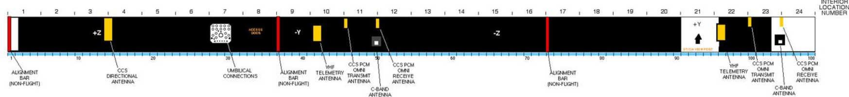
The IU is divided into 24 locations, which are marked on the interior by numbers 1-24 on the aluminum surface just above the blue flange.
4.2. Guidance and Control
The Saturn V launch vehicle was guided by navigation, guidance, and control equipment located in the IU. A space stabilized platform (the ST-124-M3 inertial platform at location 21) measured acceleration and attitude. A launch vehicle digital computer (LVDC at location 19) solved guidance equations, and an analog flight control computer (location 16) issued commands to steer the vehicle.
The attitude of the vehicle was defined in terms of three axes:
- The roll axis (X) runs from tail to nose and was vertical at time of launch.
- The pitch axis (Y) is at right angles to the roll axis, and is marked on the exterior of the IU by +Y above the viewport, outside location 21.
- The yaw axis (Z) is at right angles to both the pitch and roll axis, and is marked by +Z outside location 3.[8]
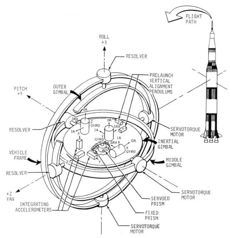
The ST-124-M3 inertial platform contains three gimbals: the outer gimbal (which can rotate 360° about the roll or X axis of the vehicle), the middle gimbal (which can rotate ±45° about the yaw or Z axis of the vehicle), and the inner or inertial gimbal (which can rotate 360° about the pitch or Y axis of the vehicle). The inner gimbal is a platform to which are fixed several components:
- Two vertical alignment pendulums sent signals before launch to ground support equipment, which generated signals to the platform gyro torque generators to level the inner gimbal. The vertical alignment system levelled the platform to an accuracy of ±2.5 arc seconds.
- Two prisms, one fixed and one servo-driven, were used with an external theodolite which sighted through the viewport outside location 21 to set the azimuth of the inner gimbal before launch. The azimuth could be set to an accuracy of ±5 arc seconds.
- Three single-degree-of-freedom gyroscopes have their input axes aligned along an orthogonal inertial coordinate system. Three signal generators, fixed to the output axis of each gyro, generated electrical signals proportional to the torque disturbances. The signals were transmitted through the servo electronics which terminated in the gimbal pivot servotorque motors. The servoloops maintained the inner gimbal rotationally fixed in inertial space. That is, while the vehicle rolled, pitched, and yawed, the inner gimbal remained in the same attitude to which it was set just before launch. Though it was being translated during the launch and orbit process, it was rotationally fixed.
- Three integrating accelerometers measured the three components of velocity resulting from vehicle propulsion. The accelerometer measurements were sent through the launch vehicle data adapter (LDVA at location 19) to the LVDC. In the LVDC the accelerometer measurements were combined with the computed gravitational acceleration to obtain velocity and position of the vehicle.
The angular positions of gimbals on their axes were measured by resolvers, which sent their signals to the LVDA. The LVDA was the input/output device for the LVDC. It performed the necessary processing of signals to make these signals acceptable to the LVDC.
The instantaneous attitude of the vehicle was compared with the desired vehicle attitude in the LVDC. Attitude correction signals from the LVDC were converted into control commands by the flight control computer. The required thrust direction was obtained by gimbaling the engines in the propelling stage to change the thrust direction of the vehicle. Gimbaling of these engines was accomplished through hydraulic actuators. In the first and second stages (S-IC and S-II), the four outboard engines were gimbaled to control roll, pitch, and yaw. Since the third (S-IVB) stage has only one engine, an auxiliary propulsion system was used for roll control during powered flight. The auxiliary propulsion system provides complete attitude control during coast flight of the S-IVB/IU stage.
4.3. Environmental Control
The environmental control system (ECS) maintains an acceptable operating environment for the IU equipment during preflight and flight operations. The ECS is composed of the following:
- The thermal conditioning system (TCS), which maintains a circulating coolant temperature to the electronic equipment of 59° ± 1 °F (15 ± 5/9 °C).
- Preflight purging system, which maintains a supply of temperature- and pressure-regulated mixture of air and gaseous nitrogen (air/GN2) in the IU/S-IVB equipment area.
- Gas bearing supply system, which furnishes GN2 to the ST-124-M3 inertial platform gas bearings.
- Hazardous gas detection sampling equipment which monitors the IU/S-IVB forward interstage area for the presence of hazardous vapors
Thermal conditioning
Thermal conditioning panels, also called cold plates, were located in both the IU and S-IVB stage (up to sixteen in each stage). Each cold plate contains tapped bolt holes in a grid pattern which provides flexibility of component mounting.
The cooling fluid circulated through the TCS was a mixture of 60 percent methanol and 40 percent demineralized water by weight. Each cold plate was capable of dissipating at least 420 watts.
During flight, heat generated by equipment mounted on the cold plates was dissipated to space by a sublimation heat exchanger. Water from a reservoir (water accumulator) was exposed to the low temperature and pressure environment of space, where it first freezes and then sublimates, taking heat from the heat exchanger and transferring it to the water molecules which escape to space in gaseous state. Water/methanol was cooled by circulation through the heat exchanger.
Preflight air/GN2 purge system
Before flight, ground support equipment (GSE) supplies cooled, filtered ventilating air to the IU, entering via the large duct in the middle of the umbilical panel (location 7), and branching into two ducts at the top that are carried around the IU in the cable rack. Downward pointing vents from these ducts release ventilating air to the interior of the IU. During fueling, gaseous nitrogen was supplied instead of air, to purge any propellant gases that might otherwise accumulate in the IU.
Gas bearing supply
To reduce errors in sensing attitude and velocity, designers cut friction to a minimum in the platform gyros and accelerometers by floating the bearings on a thin film of dry nitrogen. The nitrogen was supplied from a sphere holding 2 cu ft (56.6 l) of gas at 3,000 psig (pounds per square inch gauge, i.e. psi above one atmosphere) (20,7 MPa). This sphere is 21 inches (0,53 m) in diameter and is mounted at location 22, to the left of the ST-124-M3. Gas from the supply sphere passes through a filter, a pressure regulator, and a heat exchanger before flowing through the bearings in the stable platform.
Hazardous gas detection
The hazardous gas detection system monitors the presence of hazardous gases in the IU and S-IVB stage forward compartments during vehicle fueling. Gas was sampled at four locations: between panels 1 and 2, 7 and 8, 13 and 14, and 19 and 20. Tubes lead from these locations to location 7, where they were connected to ground support equipment (external to the IU) which can detect hazardous gases.
4.4. Emergency Detection
The emergency detection system (EDS) sensed initial development of conditions in the flight vehicle during the boost phases of flight which could cause vehicle failure. The EDS reacted to these emergency situations in one of two ways. If breakup of the vehicle were imminent, an automatic abort sequence would be initiated. If, however, the emergency condition were developing slowly enough or were of such a nature that the flight crew can evaluate it and take action, only visual indications were provided to the flight crew. Once an abort sequence had been initiated, either automatically or manually, it was irrevocable and ran to completion.
The EDS was distributed throughout the vehicle and includes some components in the IU. There were nine EDS rate gyros installed at location 15 in the IU. Three gyros monitored each of the three axes (pitch, roll and yaw), providing triple redundancy. The control signal processor (location 15) provided power to and received inputs from the nine EDS rate gyros. These inputs were processed and sent to the EDS distributor (location 14) and to the flight control computer (location 16). The EDS distributor served as a junction box and switching device to furnish the spacecraft display panels with emergency signals if emergency conditions existed. It also contained relay and diode logic for the automatic abort sequence. An electronic timer (location 17) was activated at liftoff and 30 seconds later energized relays in the EDS distributor which allowed multiple engine shutdown. This function was inhibited during the first 30 seconds of launch, to preclude the vehicle falling back into the launch area. While the automatic abort was inhibited, the flight crew can initiate a manual abort if an angular-overrate or two-engine-out condition arose.
4.5. Radio Communications
The IU communicated by radio continually to ground for several purposes. The measurement and telemetry system communicated data about internal processes and conditions on the Saturn V. The tracking system communicated data used by the Mission Ground Station (MGS) to determine vehicle location. The radio command system allowed the MGS to send commands up to the IU.
Measuring and telemetry
Approximately 200 parameters were measured on the IU and transmitted to the ground, in order to
- Assist in the checkout of the launch vehicle prior to launch,
- Determine vehicle condition and to verify received commands during flight, and
- Facilitate postflight analysis of the mission.
Parameters measured include acceleration, angular velocity, flow rate, position, pressure, temperature, voltage, current, frequency, and others. Sensor signals were conditioned by amplifiers or converters located in measuring racks. There are four measuring racks in the IU at locations 1, 9, and 15 and twenty signal conditioning modules in each. Conditioned signals were routed to their assigned telemetry channel by the measuring distributor at location 10. There were two telemetry links. In order for the two IU telemetry links to handle approximately 200 separate measurements, these links must be shared. Both frequency sharing and time sharing multiplexing techniques were used to accomplish this. The two modulation techniques used were pulse code modulation/frequency modulation (PCM/FM) and frequency modulation/frequency modulation (FM/FM).
Two Model 270 time sharing multiplexers (MUX-270) were used in the IU telemetry system, mounted at locations 9 and 10. Each one operates as a 30×120 multiplexer (30 primary channels, each sampled 120 times per second) with provisions for submultiplexing individual primary channels to form 10 subchannels each sampled at 12 times per second. Outputs from the MUX-270 go to the PCM/DDAS assembly model 301 at location 12, which in turn drives the 245.3 MHz PCM VHF transmitter.
The FM/FM signals were carried in 28 subcarrier channels and transmitted by a 250.7 MHz FM transmitter.
Both the FM/FM and the PCM/FM channels were coupled to the two telemetry antennas on opposite sides of the IU outside locations 10 and 22.
Tracking
C-band radar transponders carried by the IU provided tracking data to the ground which were used to determine the vehicle's trajectory. The transponder received coded or single pulse interrogation from ground stations and transmitted a single-pulse reply in the same frequency band (5.4 to 5.9 GHz). A common antenna was used for receiving and transmitting. The C-band transponder antennas are outside locations 11 and 23, immediately below CCS PCM omni receive antennas.
Radio command
The command communications system (CCS) provided for digital data transmission from ground stations to the LVDC. This communications link was used to update guidance information or command certain other functions through the LVDC. Command data originated in the Mission Control Center, Houston, and was sent to remote stations for transmission to the launch vehicle. Command messages were transmitted from the ground at 2101.8 MHz. The received message was passed to the command decoder (location 18), where it was checked for authenticity before being passed to the LVDC. Verification of message receipt was accomplished through the IU PCM telemetry system. The CCS system used five antennas:
- A single directional antenna outside location 3-4,
- Two omni transmit antennas outside locations 11 and 23, and
- Two omni receive antennas outside locations 12 and 24.
4.6. Power
Power during flight originated with four silver-zinc batteries with a nominal voltage of 28±2 vdc. Battery D10 sat on a shelf at location 5, batteries D30 and D40 were on shelves in location 4, and battery D20 was at location 24. Two power supplies converted the unregulated battery power to regulated 56 vdc and 5 vdc. The 56 vdc power supply was at location 1 and provided power to the ST-124-M3 platform electronic assembly and the accelerometer signal conditioner. The 5 vdc power supply at location 12 provided 5 ±.005 vdc to the IU measuring system.
References
- ‘’Stages To Saturn’’ Chapter 8.
- The Apollo "A"/Saturn C-1 Launch Vehicle System
- Saturn I Summary PDF p. 36
- ‘’Saturn Illustrated Chronology’’, Appendix H. Moonport, Appendix A. Apollo Program Summary Report, Appendix A.
- "Astrionics System Handbook", 1 November 1968, MSFC No. IV-4-401-1. IBM No. 68-966-0002. Section 1.3. Saturn V Mission Profile.
- " Instrument Unit Fact Sheet. Saturn V News Reference." Changed December 1968. Pp. 5-6.
- "Saturn V Flight Manual SA-507." MSFC-MAN-507. Changed 5 October 1969. P. 2-1 (PDF page 15). Section II. Performance. Flight Sequence.
- "Astrionics System Handbook", 1 November 1968, MSFC No. IV-4-401-1. IBM No. 68-966-0002. P. 1.2-1 (PDF p. 15): The old and new coordinate systems are described. The new standard became effective for vehicles 204 and 502 (and subsequent).


