Your browser does not fully support modern features. Please upgrade for a smoother experience.
Submitted Successfully!
 +1 credit
Thank you for your contribution! You can also upload a video entry or images related to this topic.
For video creation, please contact our Academic Video Service.
Video Upload Options
We provide professional Academic Video Service to translate complex research into visually appealing presentations. Would you like to try it?
Cite
If you have any further questions, please contact Encyclopedia Editorial Office.
Wu, J.; Li, Q.; Chen, Q.; Peng, G.; Wang, J.; Fu, Q.; Yang, B. Fault Types and Effects of HVDC Transmission Systems. Encyclopedia. Available online: https://encyclopedia.pub/entry/33894 (accessed on 23 July 2026).
Wu J, Li Q, Chen Q, Peng G, Wang J, Fu Q, et al. Fault Types and Effects of HVDC Transmission Systems. Encyclopedia. Available at: https://encyclopedia.pub/entry/33894. Accessed July 23, 2026.
Wu, Jiyang, Qiang Li, Qian Chen, Guangqiang Peng, Jinyu Wang, Qiang Fu, Bo Yang. "Fault Types and Effects of HVDC Transmission Systems" Encyclopedia, https://encyclopedia.pub/entry/33894 (accessed July 23, 2026).
Wu, J., Li, Q., Chen, Q., Peng, G., Wang, J., Fu, Q., & Yang, B. (2022, November 10). Fault Types and Effects of HVDC Transmission Systems. In Encyclopedia. https://encyclopedia.pub/entry/33894
Wu, Jiyang, et al. "Fault Types and Effects of HVDC Transmission Systems." Encyclopedia. Web. 10 November, 2022.
Copy Citation
High voltage direct current (HVDC) transmission systems play a critical role to optimize resource allocation and stabilize power grid operation in the current power grid thanks to their asynchronous networking and large transmission capacity. To ensure the operation reliability of the power grid and reduce the outage time, it is imperative to realize fault diagnosis of HVDC transmission systems in a short time.
high voltage direct current
fault diagnosis
knowledge graph
1. Development of High Voltage Direct Current (HVDC) Transmission Technology
High voltage direct current (HVDC) transmission technology has been widely used in the world as a powerful complement to alternating current (AC) transmission because of its outstanding strengths in long-distance transmission, high-capacity transmission, asynchronous networking, and submarine cable transmission. According to the different stages of commutator development, the development of direct current (DC) transmission technology can be divided into three stages: mercury arc valve, thyristor commutator, and voltage source commutator. The mercury arc valve was successfully developed in 1928. Relying on its features of rectifying and inverting, large-capacity DC power transmission was successfully realized. In 1954, the first 20 MW, 100 kV DC single-wire submarine cable was used for power transmission. However, mercury arc valves are complicated, have low reliability, and are difficult to maintain, so they have not been widely used [1].
Since the 1970s, HVDC transmission technology based on phased thyristors has become the main method of large-scale and long-distance power transmission. Compared with mercury arc valves, thyristors have a smaller volume, lower cost, and no reverse arc fault. They are simpler and more convenient to manufacture and maintain than mercury arc valves. Nowadays, most HVDC transmission systems are constructed with commutators. The commutator is intended to transfer the current flowing through the commutator from one current path to another by opening and closing the commutator valve. Line-commutated Converter HVDC (LCC HVDC) is not only the most mature HVDC transmission technology at present but also the mode mainly used in UHVDC transmission. The main converter device of LCC HVDC is the thyristor. LCC HVDC systems are mainly composed of a rectifying station, DC transmission lines, and inverter stations, where the converter, converter transformers, flat wave reactors, reactive power compensation devices, filters, DC grounding, and AC-DC switching equipment are located in the converter stations on both sides [2]. However, the operation of the LCC HVDC system requires the AC system to provide commutation support, which is limited by the system ratio [3].
In the 1990s, with the application of insulated gate bipolar transistors as converters and voltage source converters in power systems, voltage source converter-based HVDC (VSC-HVDC) technology was developed and promoted. Compared with the LCC-HVDC system, the VSC-HVDC system does not depend on the AC system and can control the active and reactive power independently and quickly. LCC-HVDC as the third generation of DC transmission technology combines a procession of power electronics, power systems, automatic control, and so on. It combines various advantages of advanced technology, which has good controllability and adaptability, a flexible operation mode, and applicable range. It plays a significant role in large-scale renewable energy integration in new power systems and digital power grid construction [4].
2. Fault Types of HVDC Transmission Systems
According to the different faulty devices, HVDC transmission system faults can be classified into DC faults and AC faults. DC faults [5] include converter faults, DC line faults, ground pole faults and so on. The converter is the core component of HVDC transmission systems, which controllability and single conduction characteristics constitute the important characteristics of faulty behavior of HVDC transmission systems. Generally, converter faults include control system faults and main circuit faults. The main circuit faults mainly include reversing faults and short circuits inside the converter station. Control system fault mainly refers to the valve being closed and opened by mistake [6]. The main failure points of a typical HVDC transmission system are shown in Figure 1 and Table 2.
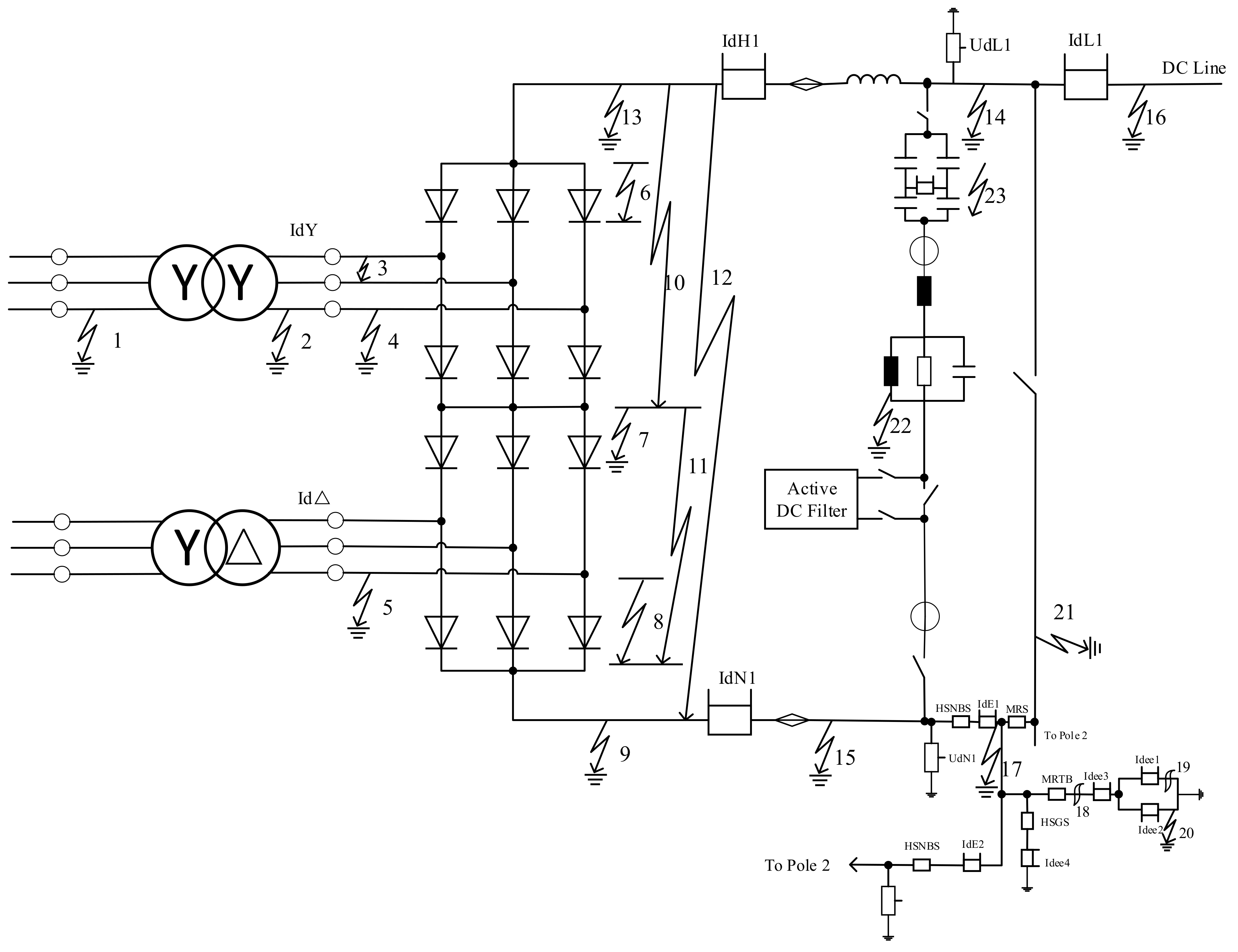
Figure 1. Major fault points of a typical HVDC system.
Table 2. Major fault points of a typical HVDC system.
| Fault Point | Number | Fault Type |
|---|---|---|
| AC side | 1 | Converter transformer inlet failure |
| 2 | Converter transformer outlet failure | |
| 3 | Converter valve AC side phase to phase failure | |
| 4 | Single-phase grounding fault on the AC side of the commutation valve | |
| 5 | Low voltage fault on the AC side of the converter valve | |
| Converter valve | 6, 7, 8, 10, 11, 12 | Short circuit fault of converter valve |
| 9, 13 | Ground fault of converter valve | |
| DC side | 14, 15, 17 | DC line ground fault |
| 16 | DC line positive grounding fault | |
| 18, 19 | Break-line fault | |
| 20 | Ground fault | |
| 21 | DC grounding electrode failure | |
| 22 | DC filter ground fault | |
| 23 | Capacitor fault |
The most serious fault of the converter is the short circuit fault; the short circuit will make the valve lose shut-off ability or the external insulation between the two ends of the valve is destroyed. When the reverse voltage peak has a large jump, the reversing valve is likely to reverse arc, resulting in a short circuit of the valve arm. In addition, when the lightning arrester short circuits or valve insulation is damaged due to cooling system leakage and gasification, this may also cause a short circuit of the valve [7]. In addition, the inverter valve arm during the blocking period is mostly under the forward voltage; if the voltage is too high or voltage rise rate is too fast, it will affect the insulation of the valve arm and make it damaged, and valve insulation damage after the valve arm will cause a short circuit.
The DC outlet short circuit of the converter is also a common fault, which is a short circuit fault between DC terminals on the converter. The main distinction between the short circuit at the DC side of the rectifier and the short circuit at the valve end is that the valve end of the converter can maintain single-lead connectivity after the short circuit occurs at the outlet of the DC side. After the short circuit at the outlet of the DC side of the rectifier, the current on the conduction valve and converter transformer increases sharply, and it needs to withstand a much higher current value than normal. In addition, the fault point of the DC outlet short circuit of the inverter is similar to that of the DC outlet short circuit of the rectifier. However, under the action of the DC line and the flat wave reactor, the fault current of the DC line and the rising speed of the current are small, and the current on each bridge valve of the inverter will be reduced to zero in a short time, so the fault will not cause harm to the inverter and converter transformer. In addition to the above fault types, the converter faults also include the alternating short circuit of the converter and single-phase ground short circuit of the converter and so on.
HVDC transmission is mainly used for long-distance transmission, so the failure rate of transmission lines is high. The transmission line fault is a serious fault type that must be considered in the design process of HVDC transmission systems. It has an important impact on equipment parameters, control strategy, and protection configuration [8]. The control system of actual HVDC transmission projects adopts a hierarchical structure, including master control stage, station control stage, pole control stage, and valve control stage. The control system not only controls the transmission power during normal operation but can also reduce the impact of faults and quickly isolate faults. For the fast transient process of DC lines, only the functional link of the control system with fast dynamic characteristics can affect it [9]. It is a problem that both LCC-HVDC transmission technology and VSC-HVDC transmission technology need to face. Among the fault types of DC transmission lines, the short circuit faults account for the largest proportion, and most of the faults are from flashover discharge. Usually, the factors that result in transmission line ground flashover include lightning strikes, pollution, DC line air insulation breakdown, tree branches, and other factors leading to the reduction of insulation level. In addition, the fault current of the line is related to the fault type and the distance from the fault point to the rectifying station [10].
The lighting characteristic of the DC line has specific characteristics. The probability of both poles of the system being struck by lightning at the same place at the same time is almost zero. Generally, the DC line is struck by lightning for a short time, and the DC voltage will rise in a short time under the effect of lightning. If the insulation of the DC line cannot withstand the voltage at this time, the phenomenon of flashover discharge of the DC line to the ground will appear.
Meanwhile, if the insulation of the tower is damaged, ground flashover will also occur. After flashover occurs on transmission lines, changes in voltage and current will be transmitted to both ends. According to the traveling wave theory, the voltage and current at both ends are the superposition of forward and backward waves [11]. If a(t) represents the forward wave, b(t) represents the backward travelling wave, and Z represents the wave impedance, then the instantaneous increment is as follows:


Moreover, interruptions in the DC line can bring open-circuit faults to the system. When a high-resistance ground fault such as a tree contact appears on the DC line, there is a current difference between the converter stations due to a DC short circuit, but the voltage and current changes caused by the fault cannot be detected by the traveling wave protection. There are also DC switching fields and ground pole faults and AC side faults of a converter station in the DC transmission system. These faults will also affect the operation of the DC transmission system.
3. Fault Effect of HVDC Transmission Systems
Generally, when a short circuit fault occurs, the DC bus voltage of the rectifier side converter will drop rapidly, even to 0; the current on the faulty valve arm will increase sharply in the opposite direction; the converter valve and transformer are affected by the sharp increase of AC side current, so they need to bear large fault current; and an AC two-phase short circuit and three-phase short circuit occur on the AC side of the rectifier [7].
The commutation faults often occur with the inverter. When commutation faults occur, the extinction angle is less than the time when the switching valve recovers the blocking ability. After the commutation failure, the DC voltage will continue to decrease until it reaches 0. Meanwhile, the DC increases sharply, while the AC side current decreases, and an open circuit occurs in a short time. In addition, DC current continuously flows through the converter transformer to generate magnetic bias. Magnetic bias refers to the presence of a DC component in the transformer excitation current, leading to the increase of excitation current, resulting in the loss and temperature rise, vibration and noise intensification, and other adverse consequences [12]. Generally, the causes of magnetic bias current include the unbalanced triggering angle of a DC converter valve, positive sequence second harmonic voltage of AC bus of the converter, fundamental frequency current induced by nearby AC line on DC line, and DC current flowing through the transformer neutral point when a DC system operates in single-pole earth loop mode. DC bias coefficient Kdc
can describe the magnitude of DC magnetic bias in transformer windings, which is defined as the ratio of peak DC current to peak no-load current, as shown in Equation (4) [13]. For other types of faults and the influence of HVDC transmission systems, see Table 3. 
Table 3. Various faults and effects of HVDC transmission systems.
| Name | Fault Type | Location of Fault | Influence |
|---|---|---|---|
| AC system of rectifier side | One-wire ground | AC line | An asymmetrical drop of AC voltage; the DC voltage and current may decrease accordingly and the non-characteristic harmonics increase. |
| Two-phase ground | AC line | An asymmetrical drop of AC voltage; the DC voltage and current may decrease accordingly and the non-characteristic harmonics increase. | |
| Three-phase ground | AC line | An asymmetrical drop of AC voltage; the DC voltage and current may decrease accordingly. | |
| Rectifier bridge | False firing | Bridge arm | DC voltage slightly rises (type I false firing) or decreases (type II false firing). |
| Not open | Bridge arm | DC voltage drop. | |
| Component failure | Valve element | The voltage applied to the element of the valve increases. | |
| Bridge arm short circuit | Bridge arm | AC increases and DC goes down. | |
| Outlet short circuit | DC bus | AC increases and DC decreases to zero | |
| DC line | One-wire ground | DC line | DC increases and an overvoltage occurs. |
| Two wire short circuit | DC line | DC increases and an overvoltage occurs. | |
| Switching overvoltage | DC line | Overvoltage | |
| Inverter bridge | False firing | Bridge arm | Voltage decreases and current increases. |
| Not open | Bridge arm | Voltage decreases and current increases. | |
| Component failure | Valve element | The voltage applied to the element of the valve increases. | |
| Bridge arm short circuit | Bridge arm | Voltage decreases and current increases. | |
| Outlet short circuit | Bridge arm | Voltage decreases and current increases. | |
| AC system of inverter side | One-wire ground | AC line | When AC voltage drops asymmetrically, the commutation may fail and the non-characteristic harmonics may increase. |
| Two-phase short circuit | AC line | When AC voltage drops asymmetrically, the commutation may fail and the non-characteristic harmonics may increase. | |
| Three-phase short circuit | AC line | When AC voltage drops asymmetrically, the commutation may fail. |
References
- Wang, L.L.; Cao, Y. Review of HVDC transmission technology. Sci. Technol. Innov. 2018, 10, 50–51.
- Tang, G.F.; Pang, H.; He, Z.Y. R&D and application of advanced power transmission technology in China. Proc. CSEE 2016, 36, 1760–1771.
- Ni, X.J.; Zhao, C.Y.; Guo, C.Y.; Liu, Y.C. The effects of VSC-HVDC on the system strength of LCC-HVDC in dual-infeed hybrid HVDC system. Proc. CSEE 2015, 35, 4052–4061.
- Zou, C.Y.; Wei, R.H.; Feng, J.J.; Zhou, Y.B. Development status and application prospect of VSC-HVDC. South. Power Syst. Technol. 2022, 16, 1–7.
- China Southern Grid Ultra High Voltage Transmission Co. Typical Fault Analysis of HVDC Transmission System Equipment; China Electric Power Press: Beijing, China, 2009; Volume 12.
- Li, X.Y. High Voltage Direct Current Transmission System; Science Press: Beijing, China, 2010; Volume 2.
- Qi, Y. The Fault Analysis of HVDC System and the Study of It’s Transmission Line Protection Scheme; East China Jiaotong University: Nanchang, China, 2012.
- Guo, J.M. Research on Fault Analysis and Protection of High-Voltage Direct Current Transmission Lines; South China University of Technology: Guangzhou, China, 2016.
- Li, A.M. A Study on Fault Analysis and Protection of the HVDC Transmission Line; South China University of Technology: Guangzhou, China, 2010.
- Zhang, F.G.; Wen, M.H.; Liu, T.; Wang, X.Z.; Yang, D.X.; Wu, T. Establishment of dynamic physical model of three-terminal UHV DC transmission line. High Volt. Eng. 2020, 46, 2064–2071.
- Zhang, C.H.; Song, G.B.; Dong, X.Z. Principle of non-unit traveling wave protection for VSC-HVDC transmission line using fault current initial traveling wave fitting. Proc. CSEE 2021, 41, 2651–2660.
- Wang, Z.Z.; Liu, K.; Li, M.Y.; Li, B.; Xu, J.W.; Zhao, J.C. Co-simulation and analysis of “Three Transformers” for UHV transformer under DC-bias. High Volt. Eng. 2020, 46, 4097–4105.
- Tong, Y.; Zhu, Q.L.; He, L.; Zhao, X.J. Analysis on DC bias impact on converter transformers operation. High Volt. Eng. 2021, 47, 2206–2213.
More
Information
Subjects:
Engineering, Electrical & Electronic
Contributors
MDPI registered users' name will be linked to their SciProfiles pages. To register with us, please refer to https://encyclopedia.pub/register
:
View Times:
8.8K
Revisions:
2 times
(View History)
Update Date:
11 Nov 2022
Table of Contents


Notice
You are not a member of the advisory board for this topic. If you want to update advisory board member profile, please contact office@encyclopedia.pub.
OK
Confirm
Only members of the Encyclopedia advisory board for this topic are allowed to note entries. Would you like to become an advisory board member of the Encyclopedia?
Yes
No
${ textCharacter }/${ maxCharacter }
Submit
Cancel
Back
Comments
${ item }
|
${ item.createdUser.fullName }
${ item.createdAt }
${ item.vote }
${ item.reply }
Delete
${ reply.createdUser.fullName }
${ reply.createdAt }
${ reply.vote }
Delete
There is no reply to this comment~
${ item.replyTextCharacter }/${ item.replyMaxCharacter }
Submit
Cancel
More
No more~
There is no comment~
${ textCharacter }/${ maxCharacter }
Submit
Cancel
${ selectedItem.replyTextCharacter }/${ selectedItem.replyMaxCharacter }
Submit
Cancel
Confirm
Are you sure to Delete?
Yes
No