Ocean energy is one potential renewable energy alternative to fossil fuels that has a more significant power generation due to its better predictability and availability. In order to harness this source, wave energy converters (WECs) have been devised and used over the past several years to generate as much energy and power as is feasible. While it is possible to install these devices in both nearshore and offshore areas, nearshore sites are more appropriate places since more severe weather occurs offshore. Determining the optimal location might be challenging when dealing with sites along the coast since they often have varying capacities for energy production. Constructing wave farms requires determining the appropriate location for WECs, which may lead us to its correct and optimum design. The WEC size, shape, and layout are factors that must be considered for installing these devices.
1. Introduction
The oil crisis of the 1970s sparked the current studies on wave energy harvesting, despite patents on this strategy from the late 18th century. The emphasis on producing power from renewable sources is a significant field of study, especially with more attention being paid to climate change and the increasing levels of CO
2. The total potential wave power resource is estimated to be 2TW. According to the Renewable 2022 World Status Report
[1], renewable energy sources account for 19.2% of the global energy consumption, traditional biomass (8.9%), and solar and wind power (10.3%) following fossil fuel usage (78.3%). The gap between the market for renewable energy and the consumption of fossil fuels may soon be closed if researchers consider recent improvements in the renewable energy sector. The global market for alternative energy sources increased from 85 GW in 2004 to 560 GW in 2013 (excluding hydropower)
[2][3][4]. With an increase from 48 to 318 GW, the wind industry took the lead in the sector. A number of variables, such as governmental backing, financial incentives, and falling technological prices that made renewable energy affordable, contributed to the revolution in this renewable industry.
The capacity of the global ocean’s sources is immense, considering the wide range of available marine natural resources and massive sea surfaces. Waves, tidal and ocean currents, ocean thermal energy, salinity gradients, marine biomass, and deep ocean geothermal energy are only a few potential energy sources in the ocean. Offshore wind is a practical application of marine ecology. There are now 81 offshore wind farms in Europe with a combined capacity of 12.6 GW, which are owned by 10 different European countries. In 2016, it was estimated that by 2020, the entire capacity would reach almost 24.6 GW
[5][6][7][8][9][10][11]. The average sea depth for an offshore wind farm is 29 m (+12% from 2015), and the spacing to the coast is 44 km. These current technology advancements are used to make this projection. Since 2000, the offshore wind energy industry has been steadily growing, resulting in the construction of wind farms, turbines, and areas of coastline that are bigger and longer. In 2015, investments in transmitting infrastructure and new wind farm projects amounted to ~USD 18 billion
[12].
With regard to maritime energy sources, wave power is still in its infancy. Specific environmental conditions must be present for wave power to be produced. Total wave energy is composed of potential energy, created as water is pushed up and down against gravity, and kinetic energy, created when the water’s velocity changes. To utilize wave energy, a structure must collect and harvest it effectively
[13][14][15]. The structure must also withstand the sea environment, especially during storms when the wave force rises dramatically. A stationary generator with moving components (on the ocean floor or coastline) transforms wave energy into mechanical energy
[16]. In recent decades, floating devices that can be used offshore have been introduced. The floating systems may be built and aimed to benefit from both kinetic and potential energy, either alone or together.
There are two types of waves in the ocean, namely wind seas (locally produced waves) and swells (waves generated by distant winds). Waves are produced by winds that can travel long distances with a minimal loss; hence the wave energy industry might rival offshore wind. Since swell waves often have a more constant energy density, they are more significant to the wave energy converter (WEC) sector
[17][18]. Only a tiny fraction of the ocean’s wave power potential is properly collected at local “hotspots,” which refer to the surrounding shores, islands, and semi-enclosed basins. Hotspots generally represent the optimal trade-off between the wave energy potential and other factors, including the distance from the shore, water depth, and initial investment expenses. The Pico Island facility in Portugal and Islay plant in Scotland are only the two examples of recent onshore and offshore developments. The Land Installed Marine Power Energy Transmitter (LIMPET) plant was built and tested as part of the Islay project. This system, which was installed in 2000 on an island off the west coast of Scotland, is made up of three horizontally inclined concrete water columns. Two turbines in opposing wells, operating at 700–1500 rpm, convert the vertical motion of the water into usable power
[19][20][21]. The Instituto Superior Técnico (IST) in Lisbon, oversaw the 400-kW Pico plant development in the Azores between 1995 and 1998. However, several problems surfaced due to the existing infrastructure and machinery. The project was revised in 2005, and by 2009, its creators claimed it had run without interruption for 265 h. Most of these systems are still in the prototype stage, and only a tiny fraction of generators has undergone extensive testing in maritime environments. All aspects of the systems, including their ability to generate electricity and adapt to unforeseen survival challenges, have been examined and evaluated
[12][22][23][24].
Given the current lack of significant wave farms, the industry’s outlook is growing as new technologies become available. The European wave sector has the capacity to produce 188 GW by 2050, equivalent to 10% of the total European power demand. However, this scenario is contingent on the introduction of a state-of-the-art wave generation system, which is expected to occur between 2022 and 2040. The R&D of a current project has sparked new ideas about how the price of wave technology might be lowered in the future. Specifically, future wave technology developments may reduce the expenses of power take-off (by 22%), installation (by 18%), operation and maintenance (by 17%), foundation and mooring (by 6%), and grid connection (by 5%)
[12][25][26]. Sharing infrastructure between WECs and the preexisting offshore wind farms is an attractive possibility for cost savings. In regions with a modest potential for wave energy, this might help speed up and expand the wave industry. By the end of 2050, it is projected that 7% of the world’s electricity will be produced by renewable energies, such as wave, wind, tidal, and solar power, to combat the unsustainable use of fossil fuels and the environmental damage that results from their excessive usage. Wave energy is a preferred alternative among these renewable energy sources due to its high energy density and environmentally acceptable characteristics.
2. Wave Energy Resource and the WEC Mechanism
2.1. Wave Energy Characteristics
In recent years, renewable energy sources have been hailed for their potential to lessen the environmental damage caused by the extraction of fossil fuels. In particular, Glendenning (1977)
[27] reported that wave energy is blossoming into a viable alternative power source and should be taken into account, due to its greater energy density and reliability than other sources. In order to make the most of this resource and to maximize energy harvesting, it is important to thoroughly study the temporal and spatial wave changes on the nearshore, as suggested by Neil and Hashemi (2013)
[28]. Over the last several years, many wave resource evaluations in various coastal regions across the globe have been conducted using the established approaches, such as the numerical modeling of the nearshore wave conditions
[13][29][30][31][32].
WECs are designed to operate in certain wave climates, and the peculiarities of the sea states also affect how much power they can produce
[33][34]. Therefore, the differences in the power range of WECs, based on the wave conditions should be evaluated along with the available energy resource to select the best locations for a wave energy plant. However, the majority of the analyses of wave energy resources are restricted to assessing the wave energy resources in a specific coastal region and identifying the sites with the maximum transformation
[35][36]. In light of these considerations, the innovative approaches for the wave energy evaluation must be created in order to pinpoint more precisely the locations with the most significant potential for collecting wave energy.
The different hydrodynamic modeling methods, such as Delft3D-Wave
[37], XBeach
[38], WaveWatch III
[39], and the standalone Simulating WAve Nearshore (SWAN)
[40][41][42], are well-verified wind-wave models that may be used to analyze the wave energy resource and identify the nearshore hotspots. The best locations for harvesting wave energy are those where the wave energy is concentrated due to the combined effects of refraction and shoaling. The model inputs include offshore wave characteristics collected at a wave buoy and coastal bathymetry. The nearshore wave simulations using the SWAN model have been performed for some time and are anticipated to improve further.
The Delft University of Technology developed the spectral model SWAN
[42], based on third-generation wind-wave modeling, which forecasts the wave characteristics in shallow water. The wave action balancing equation is solved by SWAN using sources and sinks as follows:
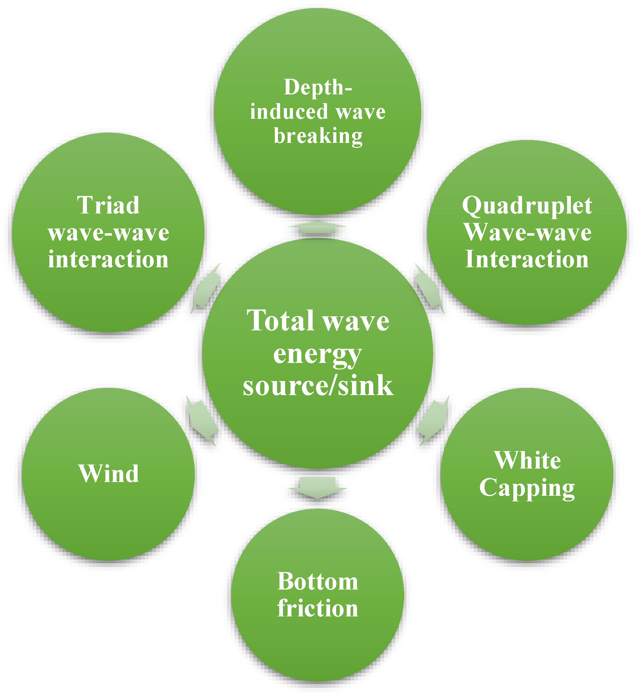
where N=N(σ,θ;x,y,t) denotes the action density; σ is the relative radian frequency; θ is the wave direction; x and y are the space variables; t is the time; cg,x, cg,y, cθ and cσ are the group velocities in the geographical space and in the spectral space (σ, θ), respectively. Stot=Stot(σ,θ;x,y,t) is the sum of the physical processes of the wave energy generation, dissipation, and redistribution:
The parameters of Equation (2) are graphically illustrated in Figure 1.
Figure 1. Source terms of wind-wave models.
2.2. Wave Energy Converter Types
The first WECs were installed in 1973 by Salter
[43], who investigated the feasibility of wave power.
The amount of literature in this area has grown exponentially since the turn of the century. At present, there are at least six widely recognized categories of conversions, each of which is based on a different combination of factors, including the installation site, the PTO system type, the working regulations, whether the conversion is floating or submerged, and the number of degrees of freedom (DOFs) it possesses. These devices are categorized into different types, such as floating, fully submerged, partly submerged, and devices located on the sea floor. Six DOFs can be broken down into two sections. The first component includes the translational movement, such as heave, sway, and surge, while the second part carries the rotational degrees, such as roll, pitch, and yaw DOFs. WECs may be categorized based on the number of DOFs. The installation site for the conversions is divided into three sections. First, the WECs erected near the coastline or linked to man-made structures, such as breakwaters, are referred to as onshore systems. Second, the nearshore systems are positioned 500 to 2000 m from the coast at a depth of 10 to 25 m. Around a quarter of wavelengths are presented in the nearshore areas. Eventually, the WEC technologies vary from 40 to 100 m respective to the depth of the WEC installations, making adaptive conversions problematic due to the incoming waves
[44]. The various WEC type categories are briefly described below.
2.2.1. Point Absorbers
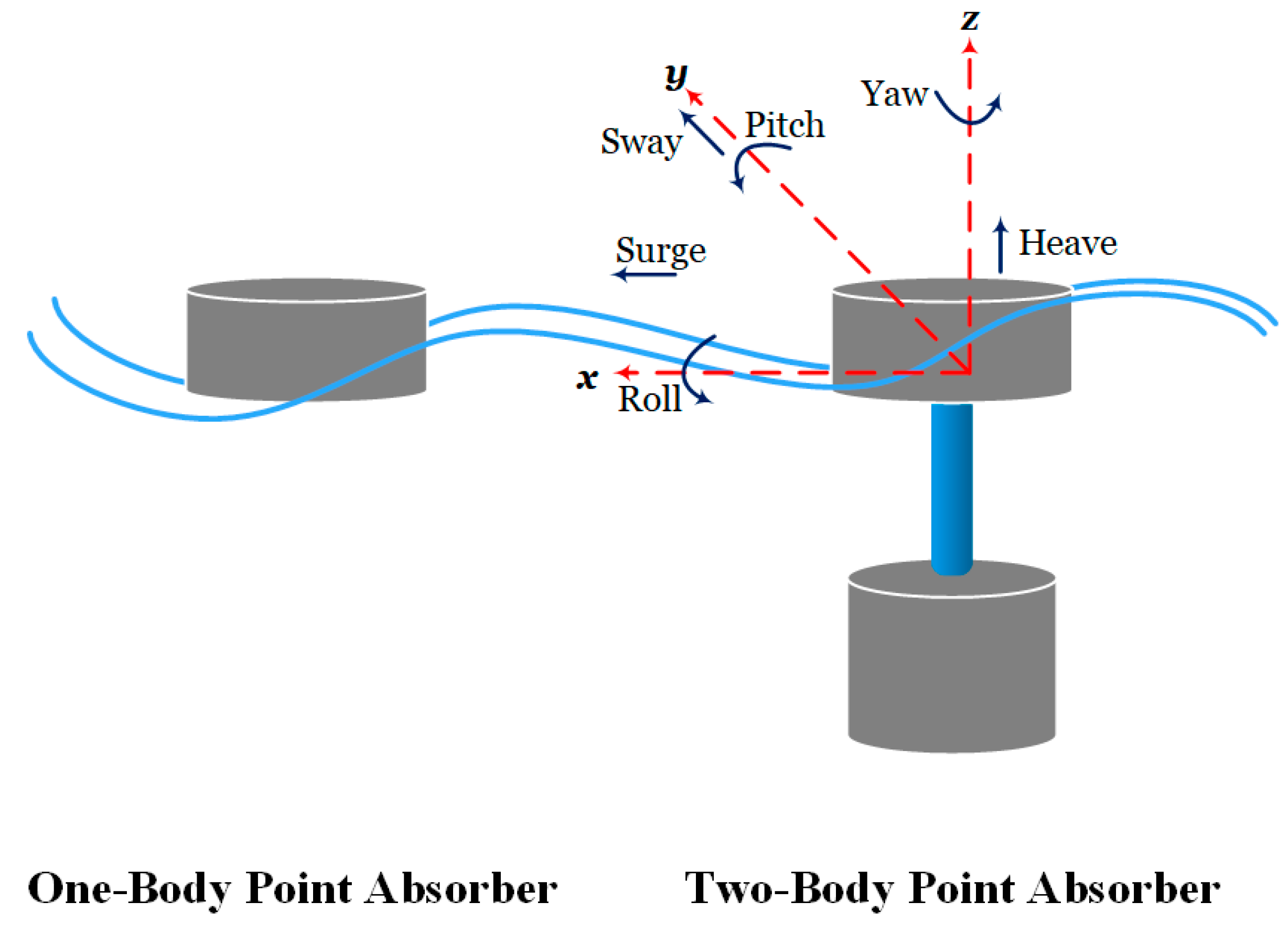
As a kind of WEC device, the point absorbers (PAs) have features and shapes thinner than the incident wavelength. The point absorbers may function in heave, pitch, or multiple DOFs, can be installed onshore or offshore, and can act as one- and two-bodies based on the number of bodies involved. While the latter (two-body) are absolute displacement references about the seabed or offshore structures, the majority of the former (one-body) are self-referenced. The standard shapes of one- and two-body PAs are shown in Figure 2.
Figure 2. Common point absorbers.
The PAs with one-body interact with the ocean waves using a single body that is either floating or submerged, and the body’s motion drives a stationary PTO device to generate the energy. The body’s natural frequency and response amplitude operator (RAO), an essential part of the dynamics, shows a low-pass behavior in the frequency domain and significantly impacts the body’s geometrical structure. The two-body point absorbers use two bodies’ relative motion and may operate offshore without requiring mooring devices since they do not need a fixed point of reference. The band-pass properties are unique to the two-body PAs, which allow the band-pass to be tuned to specific wave spectra
[45]. The two-body PAs have more complicated geometric forms and need more parameters to specify their geometries than the one-body PAs. Unlike the one-body PAs, which work as low-pass filters, the two-body PAs function as band-pass filters, with the appropriate bandwidths being very sensitive to the geometric forms.
2.2.2. Oscillating Water Columns
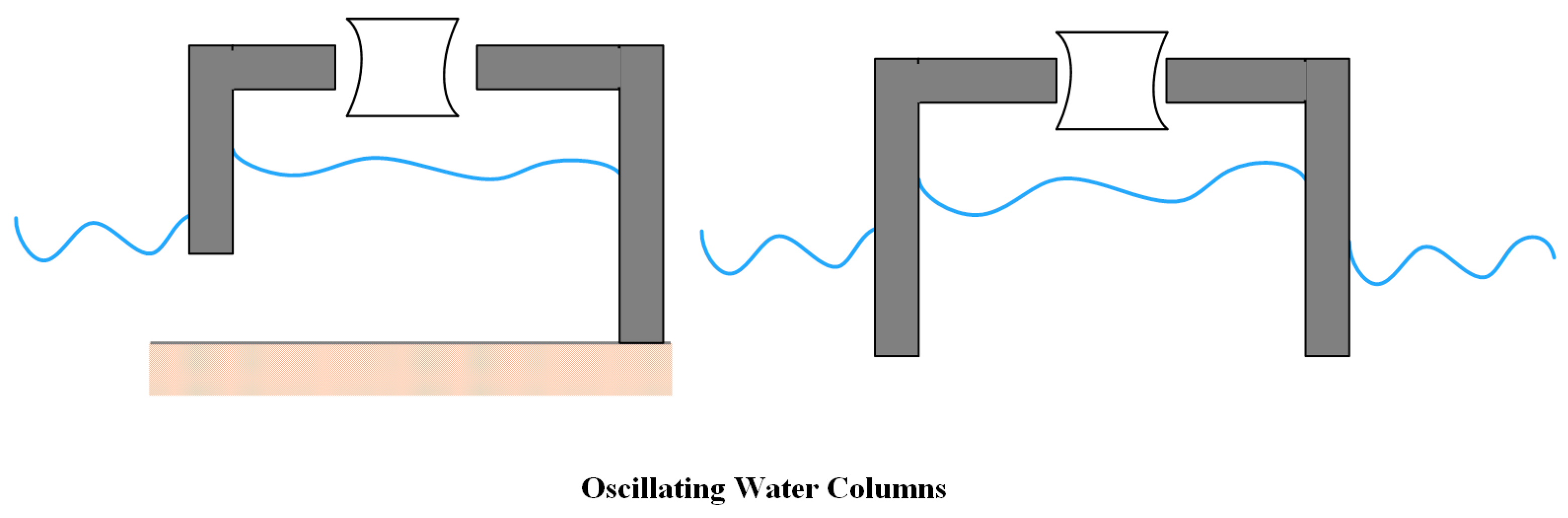
An open structure with an open inlet is used in an oscillating water device to trap air above the inner free surface and above the still water level. The trapped air is compressed and released by the wave action in alternating cycles by opening a valve that directs the airflow into a turbine connected to a power plant
[46]. The oscillating wave columns (OWCs) do not need an end-stop function since there is no oscillating linear motion present in them. The two types of OWCs are floating and fixed, whereby the fixed OWCs are connected to the breakwaters or the shore
[47].
Figure 3 illustrates examples of these OWCs. One significant benefit of fixed OWCs is that other functional needs, such as breakwaters
[48], may split the costs for the infrastructure, resulting in a reduced levelized cost of energy (LCoE). In addition, the testing conducted in open water on the permanently installed OWCs proves their reliability and resilience in extreme weather and waves
[24].
Figure 3. Fixed (left) and floating (right) OWC.
2.2.3. Attenuators
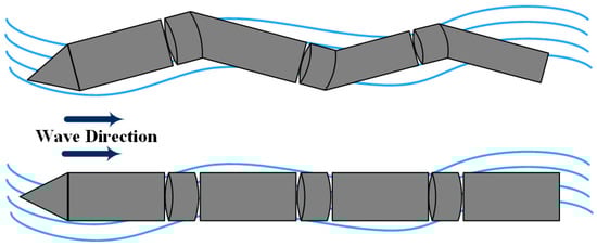
Parallel to the direction of the waves, the attenuators are free-floating WEC devices made up of a series of bodies linked by hinges, such that the motion of one body relative to another may power a PTO. As seen in
Figure 4, the Pelamis
[49] is a prominent example of an attenuator-type WEC.
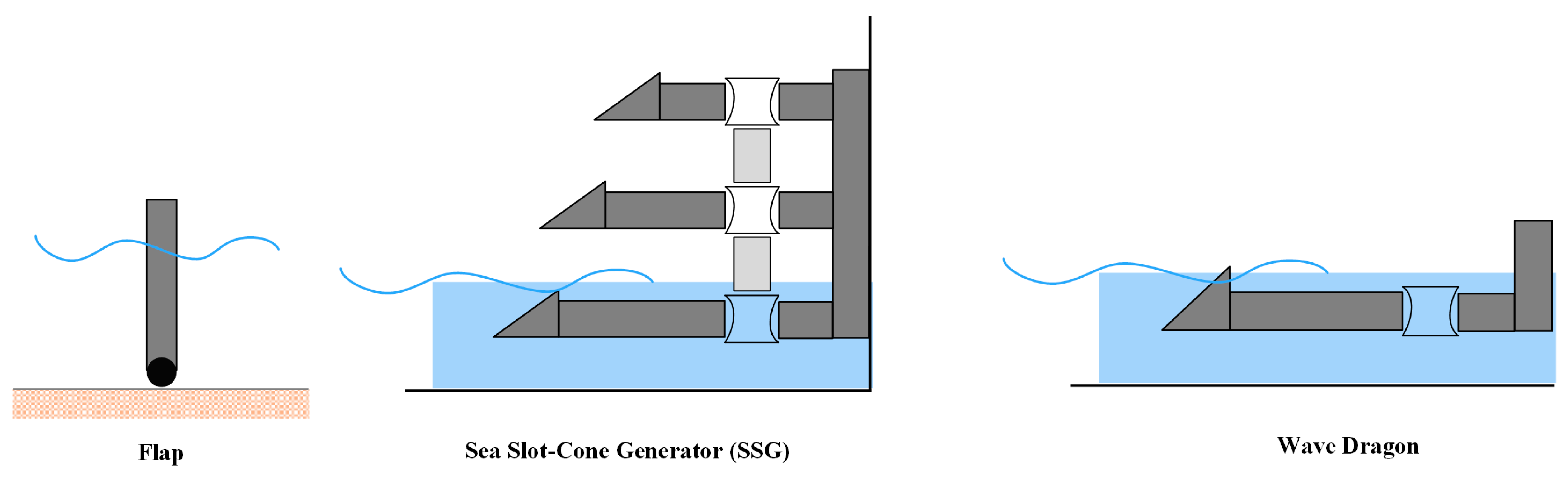
2.2.4. Terminators
The overtopping technologies, the oscillating wave surge converters (OWSCs), and the “duck-like” systems are all examples of terminators that are positioned perpendicular to the wave direction. Flaps, flaps with vanes, cylinder C-cell shapes, and flaps with arbitrary designs are all used in OWSCs to facilitate the interaction between the wave and the structure. The most important factors to consider while designing these forms are the flap size and depth to which they are submerged. There is some overlap between the categories of the PA and OWSC. However, in this context, the cylindrical devices are considered OWSCs since their working principle and optimization strategy are similar to those of other OWSCs. The overtopping devices, such as the WD and the sea slot-cone generator (SSG), as depicted in
Figure 5, rely on the angle, freeboard and draught, and the ramp shape to function at their best
[50][51][52].
Figure 5. Terminator types of WECs.
2.3. Power Take-Off Mechanism
The mechanism that transforms the electrical energy generated by the primary conversion is known as the PTO. The direct conversion may be seen in a PA buoy or a water column resonator chamber. The efficiency with which the absorbed wave power is transformed into electricity is directly related to the PTO system’s influence on the wave energy converter’s mass, dimensions, and structural dynamics.
The PTO system has a direct effect on the LCoE
[53] since it affects the efficiency with which the wave energy is converted. The PTO system directly influences the effectiveness of the power conversion and, hence, the annual energy generation. The capital cost of a device is directly affected by the PTO system, which accounts for around 20–30% of the total cost
[54]. How well the PTO system functions determines on how much it costs to run and maintain, as well as how much energy it produces.
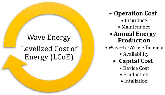
Figure 6 displays a schematic of the PTO’s impact on the LCoE
[55]. The PTO variables were studied by the Danish organization Partnership for Wave Energy to determine the impacts of improvements in the PTO efficiency and the PTO framework cost reduction on the LCoE.
Figure 6. Parameters defining the LCoE for the WECs.
A decrease in the LCoE is associated with both an efficiency improvement and the PTO cost reduction. Although a boost in the PTO performance has a more noticeable impact on the LCoE, both variables significantly impact the LCoE, indicating the importance of the PTO system in a wave energy conversion.
3. Recent Advances in Optimizing the WEC Configuration
3.1. Optimization Approaches
Converging to the best solution directly in most actual engineering issues is difficult. Yet, putting up a loss function that gauge’s the solution quality and decreases its parameters to discover the best possible solution is not easy. Some of the research initiatives explore numerical approaches. This section thoroughly discusses several optimization methods applied in the WEC systematic design.
Noad and Porter
[56] used a multi-dimensional numerical optimization to assess the solution method’s correctness and to determine the appropriate device settings for the array optimization. The design of the WEC arrays was described by Ruiz et al.
[57], using four parameters, as well as looking at the GA, the glowworm swarm optimization (GSO), and the CMA-ES. In contrast to the GA and GSO, the CMA requires less processing power, as found by the researchers. Raju
[58] employed the Nelder–Mead (NM) search method to determine the best PTO parameters for each WEC and the derivative-free continuous optimization, the CMA-ES, to enhance the conversion location by minimizing the negative interactions.
Thomas et al.
[59] presented a shallow artificial neural network (ANN) to find the ideal latching times in irregular wave situations. According to the results, for particular sea conditions, the learnable WEC absorbs twice as much power as the WEC without latching and 30% more power when compared to the test wave’s best consistent latching time. Complex PTO control methods, such as the latching-declutching optimization, aim to improve the overall system performance. Due to the discontinuous nature of the loss function in this optimization issue, Feng and Kerrigan
[60] opted to adopt a novel derivative-free coordinate-search approach, developing a formulation based on historical wave data and forecasting future wave behavior. To demonstrate the algorithm’s effectiveness, it was compared to the simulated annealing (SA) algorithm, a global meta-heuristic technique without derivatives.
The bio-inspired algorithms use simple, naturally derived techniques to address complicated issues. Since many biological processes may be considered a local optimization, these techniques imitate nature. They fall under the scope of randomized algorithms and extensively use arbitrary choices. This method has gained much popularity because it can be used to tackle complicated issues in all major branches of computer science and offers solutions to a wide variety of issues. Bio-inspired algorithms have been divided into many categories, including ecology-based, multi-objective, many-objective, and EAs.
3.2. Layout-PTO-Geometry Optimization
Numerous studies investigated the prospect of enhancing the array’s capacity to absorb energy by considering various designs. Such arrangements may result in a 30% reduction in the array or even a growth of around 5%. Over the last decade, many researchers have examined the uncomplicated regular, and unpredictable patterns and found that the optimized patterns may be a solid option to impact extracting power positively.
A number of variables influence the placement of buoys in an array, which could be beneficial or destructive depending on the project’s ultimate objective. In particular, the closer WECs are to one another, the greater the adverse effects when less expensive cabling is used. The six most important elements in designing an array are discussed as follows. First, the number of WECs profoundly affects the overall design, whereby more than four transformations are needed for the polygonal and circular designs. Second, the array’s behavior may shift if each conversion is handled separately. Therefore, the power absorbed by an array would be the same as the power of the isolated powers, and the interaction effects of the array may even be negligible. Third, the power absorption characteristic is very sensitive to sea conditions. As a result, the wave interaction effects are applicable, and a lot of energy is consumed when the natural period of the system is similar to the wave period. In the case of regular waves, the wave’s direction and frequency also directly affect the excitation force. The interaction factor is susceptible to the strength of the excitation force used on the device. Fourth, the direction of the waves may have a significant role in determining the design. This may be tested in two ways: theoretically by rotating the array pattern or experimentally by employing different definitions at different points in the study. Despite the fact that most publications solely take into account unidirectional waves, the correlation of multidirectional waves also needs consideration. Fifth, the amount of energy harvested from each WEC is affected by its individual size. Finally, it is essential to consider how waves interact with the buoys when placing them to minimize the detrimental effects.
Table 1 presents the examples of the most recent literature that meet the requirements for selecting the optimal design of a WEC array, as part of their configurations, numbers of WECs, and types of conversion.
Table 1. Summary of the recent publications on the WEC array optimization.
| Author(s)–Year |
WEC Type |
WEC No. |
Objective Function |
Algorithm |
Ref. |
| PA |
OWC |
Attenuator |
Terminator |
| Deandres (2014) |
✓ |
|
|
|
2, 3, 4 |
q-factor |
GA + Parabolic Intersection |
[61] |
| Baltisky (2014) |
|
|
✓ |
|
2, 3, 4, 5, 6 |
Mean AEP |
Global Control |
[62] |
| Noad et al. (2015) |
|
|
|
✓ |
3, 5 |
Absorbed power |
Multi-Dimensional Optimization |
[56] |
| Blanco et al. (2015) |
✓ |
|
|
|
2 |
Maximize power |
EA |
[63] |
| Sharp & DuPont (2016) |
✓ |
|
|
|
5 |
Power and cost |
GA |
[64] |
| Wu et al. (2016) |
✓ |
|
|
|
25, 50, 100 |
Computational cost |
EA and CMA-ES |
[65] |
| Sarkar et al. (2016) |
|
|
|
✓ |
40 |
Maximize power |
GA and Monte Carlo |
[66] |
| Ruiz et al. (2017) |
|
✓ |
|
|
>10 |
Maximize power |
CMA-ES, GA, GSO |
[57] |
| Ferri (2017) |
✓ |
|
|
|
>50 |
Computational cost |
CMA-ES + MM |
[67] |
| Giassi et al. (2017) |
✓ |
|
|
|
9, 12 |
Maximize power |
GA |
[68] |
| Blanco et al. (2018) |
|
|
✓ |
|
2 |
Maximize power |
EA |
[69] |
| Sharp and DuPont (2018) |
|
|
|
✓ |
5 |
Power and cost |
GA |
[70] |
| Giassi et al. (2018) |
✓ |
|
|
|
4–14 |
Maximize power |
GA + Multiple Scattering |
[71] |
| Fang et al. (2018) |
✓ |
|
|
|
3, 5, 8 |
Maximize power |
EA |
[72] |
| Neshat et al. (2018) |
✓ |
|
|
|
4 |
Maximize power |
Meta-Heuristic Algorithm |
[73] |
| Lyu et al. (2019) |
✓ |
|
|
|
3, 5, 7 |
Optimal control |
GA |
[74] |
| Vatchavayi (2019) |
✓ |
|
|
|
4–9 |
Maximize power |
CMA-ES |
[58] |
| Neshat et al. (2019) |
✓ |
|
|
|
16 |
Maximize power |
Neural Optimization + Analytical |
[75] |
| Faraggiana et al. (2019) |
✓ |
|
|
|
1–3 |
Minimize LCoE |
PSO and GA |
[76] |
| Neshat et al. (2020) |
✓ |
|
|
|
49, 100 |
Maximize power |
Multi-Strategy EAs |
[77] |
| Neshat et al. (2020) |
✓ |
|
|
|
4, 16 |
Maximize power |
Cooperative EAs |
[78] |
| Bosma et al. (2020) |
|
✓ |
|
|
5 |
Average power |
- |
[79] |
 +1 credit