The battery charging procedure has different definitions and requirements. One of the most important definitions is the battery C rating. The battery capacity is usually rated at 1C (1C current). A 400 V battery with 100 kWh capacity can be charged or discharged with 250 A within one hour. This means that with the use of 1 kA of current, the battery can be recharged in 15 min. Therefore, an increase in C rating yields a faster charging or discharging time. However, C rate increase has technically some limitations, including increases in internal energy losses, battery thermal tolerance, and reducing battery’s life-cycle. The 6C rate of charging is considered as an ultra-fast charging method according to the US Department of Energy (DOE). As a result, a trade-off exists between ultra-fast charging and battery health. Different possible configurations of DC ultra-fast charging stations are AC-coupled, DC-coupled, and hybrid-coupled.
1. Introduction of DC Ultra-Fast Charging Station
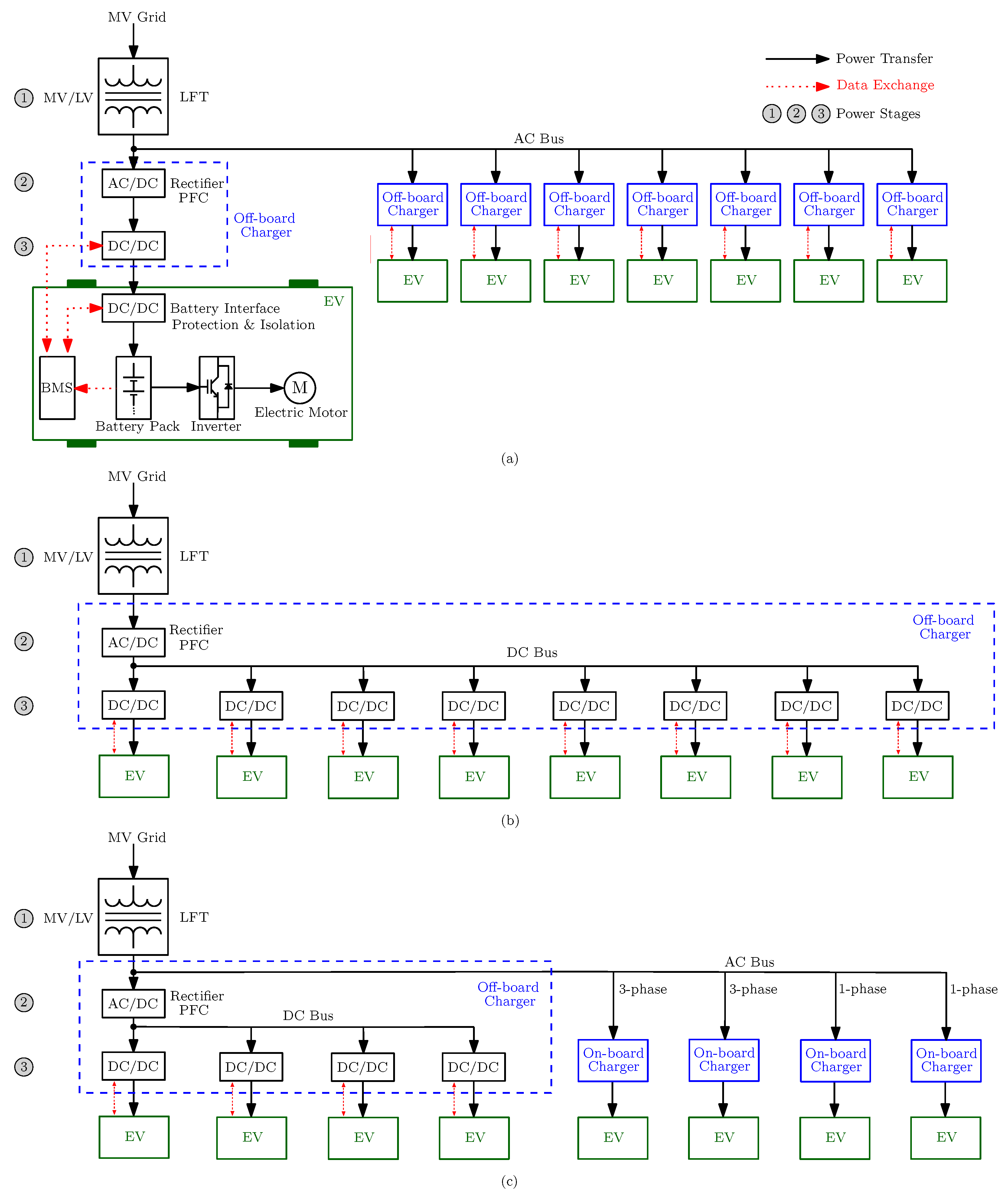
Different possible configurations of DC ultra-fast are shown in
Figure 1. In this figure, all the power flows could be bidirectional to satisfy vehicle-to-grid (V2G), vehicle-to-home (V2H), and vehicle-to-vehicle (V2V) applications in the future smart grids
[1]. To deliver the power to or from an EV, bidirectional power electronic converters are used, which are comprehensively reported in
[2]. An example of an AC-coupled DC ultra-fast charging station is in Mountain View, California, with six superchargers and a 400 kWh integrated energy storage for load shaving within peak hours. The AC-coupled DC ultra-fast charging station has some advantages such as appropriate converter technology, switchgear, protection devices, and well-established standards. The only disadvantages of AC-coupled stations is the huge amount of used power converters in order to integrate with the DC systems, which leads to more complex and less efficient systems. In addition, some control challenges appear in the island mode of operation such as reactive power control, inverter synchronization, and voltage/frequency control. The DC-coupled configuration, shown in
Figure 1b, has less conversion stages, higher efficiency, and a simpler control structure, although it has a complex protection scheme and non-standardized metering
[3]. Moreover, the integration of renewable energies and energy storage is more simple. In addition, the proposed structure of a DC ultra-fast charging station with a bipolar DC bus in
[4] can solve the grounding issue of the DC network
[5][6]. In the hybrid-coupled charging station, shown in
Figure 1c, which is a combination of a DC-fast charger and single-phase and three-phase AC chargers, the system suffers from load nonlinearity problems due to the use of power electronic converters as well as unbalance issues due to the connection to single-phase chargers or different fast charging pilot power requirements.
Figure 1. The LFT-based ultra-fast charging station configurations: (a) AC-coupled; (b) DC-coupled; (c) hybrid-coupled.
As reported in Table 1, the supercharger maximum power existing in the EV market is 250 kW. Consider this value as the maximum peak charging power; therefore, the maximum peak power required in the eight-slot DC-coupled DC ultra-fast charging station (Figure 1b) would be 2 MW whenever all the pilots are simultaneously charging the EVs with the lowest SOC. This is the worst-case scenario that could happen in the charging station. It should be considered that, due to the differences in the SOCs of EV batteries, the charging power delivered to each battery could be different.
Table 1. Battery characteristics for some of EV manufacturers.
| Car Model |
Battery Type |
Capacity |
Voltage |
Range |
Fast-Charging Time |
Supercharger Maximum Power |
| Tesla Model Y |
Li-ion |
75 kWh |
360 V |
487 km |
31 min |
250 kW |
| Tesla Model X |
Li-ion |
100 kWh |
350–375 V |
536 km |
28 min |
250 kW |
| Tesla Model 3 |
Li-ion |
50–75 kWh |
350–400 V |
507 km |
31 min |
250 kW |
| Tesla Model S |
Li-ion |
103 kWh |
400 V |
637 km |
27 min |
250 kW |
| Volkswagen ID.3 |
Li-ion |
62 kWh |
408 V |
415 km |
38 min |
125 kW |
| Volkswagen ID.4 |
Li-ion |
77 kWh |
400 V |
514 km |
38 min |
125 kW |
| Volkswagen ID.5 GTX |
Li-ion |
82 kWh |
400 V |
490 km |
33 min |
135 kW |
| Renault Zoe E-Tech |
Li-ion |
52 kWh |
375 V |
390 km |
78 min |
50 kW |
| Renault Megane |
Li-ion |
60 kWh |
400 V |
360 km |
54 min |
130 kW |
As shown in
Figure 1, the DC ultra-fast charging station has three power stages, which are listed below. The power stages and utilized power electronic converters inside the EVs can be found in
[7].
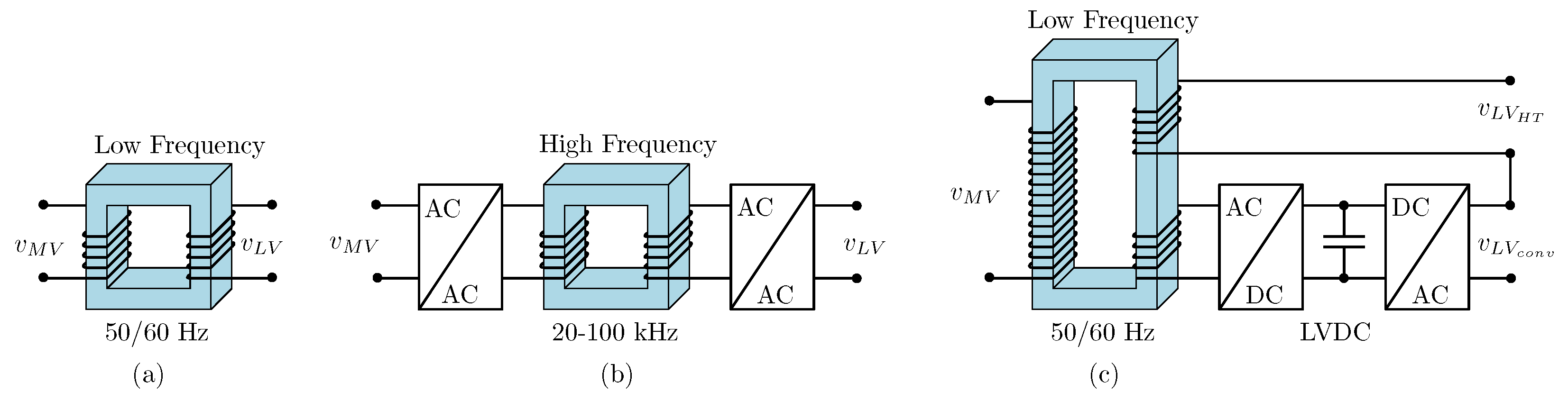
2. Power Stage 1
The first power stage is the voltage level change. The huge amount of power required in the DC ultra-fast charging station should directly be provided from the MV distribution line. Since the battery chargers work at less than 1000 V, a transformer is required to step-down the voltage level. Different types of transformers are used in the literature to step-down the voltage level in power systems, including LFT, SST, and HT
[8]. These are shown in
Figure 2 [9].
Figure 2. Different types of transformers: (a) LFT; (b) SST; (c) HT.
The LFTs are bulky in size, weighty, and suffer from a high installation cost. There is no control freedom in the input/output voltage/current of the LFTs. Although with mechanical tap changers, the voltages can be controlled to a limited extent, this is not sufficient in the fast voltage fluctuations of modern power systems in which the penetration of intermittent renewable energies, EVs, and DC ultra-fast charging stations is high. An alternative solution is to use HT, which is the combination of a power electronic converter in the input/output of the LFTs (
Figure 1c). Thanks to the power converter installation, the integration of energy storage in the HT DC link is possible. The converter power rating is usually between 5–20%, which gives controllability to some extent. However, HT is also bulky and weighty. Another alternative solution is to utilize SST, which can provide full control freedom in the input/output voltage/current such as reactive power control, voltage regulation, and harmonic control. Furthermore, the integration of energy storage and renewable energies is very simple. The SST has advantages including a reduced overall cost and compact size, which are explained in detail in the next section. However, due to the switching and conduction losses in SSTs, their efficiency is lower than the LFTs
[10]. The research is still open to improve the SST efficiency specifically in high-power applications.
3. Power Stage 2
The second power stage in the DC ultra-fast charging station is AC to DC conversion, which is responsible for the PFC
[11]. In this power stage, the converter rectifies the three-phase input AC voltage to a fixed output voltage in the DC link provided that the power quality is desirable on the grid side. Different kinds of power converters are used for this power stage. The AFE rectifier, which is also called an active pulse width modulated (PWM) rectifier, is one of the most used three-phase power converter for this power stage thanks to its high reliability and simplicity. It is used in boost
[12], buck
[13], and buck–boost
[14] modes of operation. Other used simple topologies that can keep the system modularity are half bridge (HB), full bridge (FB), and four-switch buck–boost converter
[15] separately used in each phase. Other proposed topologies are multilevel
[16], such as the cascaded H-bridge (CHB) converter, modular multilevel converter (MMC), three-level boost (TLB) converter, three-level T-type (TLT) rectifier, multi-cell boost (MCB) converter, neutral point clamped (NPC) converter
[17], multi-pulse AC–DC converter
[18], and Vienna rectifier (VR)
[19][20]. A comprehensive state-of-the-art of AC–DC converters can be found in
[21]. The L, LC, and LCL input filters are normally added to the converter input side to desirably satisfy the grid-code requirements as well as to reduce electromagnetic interference (EMI). In both modes of bidirectional AC–DC converter operation, PFC and IEEE-519 grid requirements should be satisfied.
4. Power Stage 3
The last power stage in the DC ultra-fast charging station is DC–DC conversion with multi-functional applications, such as stepping-down the input voltage to the battery voltage level, galvanic isolation to separate the EV from the grid, and cooperation with BMS to satisfy battery optimal charging
[22]. Similar to power stage 2, the used converters in this stage can be unidirectional and bidirectional. From another point of view, they can be galvanically isolated or nonisolated DC–DC converters. On the one hand, the EV’s battery is not grounded; therefore, its direct connection with the isolated DC–DC converter secondary side will isolate it from the grid
[3]. As a result, its protection scheme can work separately from the grid. On the other hand, if the isolation is performed by LFT, nonisolated DC–DC converters could be a promising solution with less complexity to operate in bidirectional power flow mode. Examples of unidirectional isolated DC–DC converters are the phase-shifted full-bridge (PSFB) converter
[23], interleaved PSFB converter
[24], LLC resonant converter
[25], and buck–boost three-level semi-dual-bridge
[26]. Examples of bidirectional isolated DC–DC converters are the dual active bridge (DAB)
[27], dual half bridge (DHB)
[28][29], LLC series-resonant converter (LLC-SRC)
[30], quad active bridge (QAB)
[31], DAB-based active NPC (DAB-ANPC)
[32], and CLLC converter
[33]. A comprehensive review of isolated DC–DC converters is reported in
[34]. Since the battery voltage level is normally lower than the DC link voltage of AC–DC converters, nonisolated DC–DC converters can be categorized as a buck converter
[35], interleaved buck converter
[36], unidirectional TLB converter
[37], bidirectional TLB converter
[38], and three-level flying capacitor (FC) converter
[39][40].
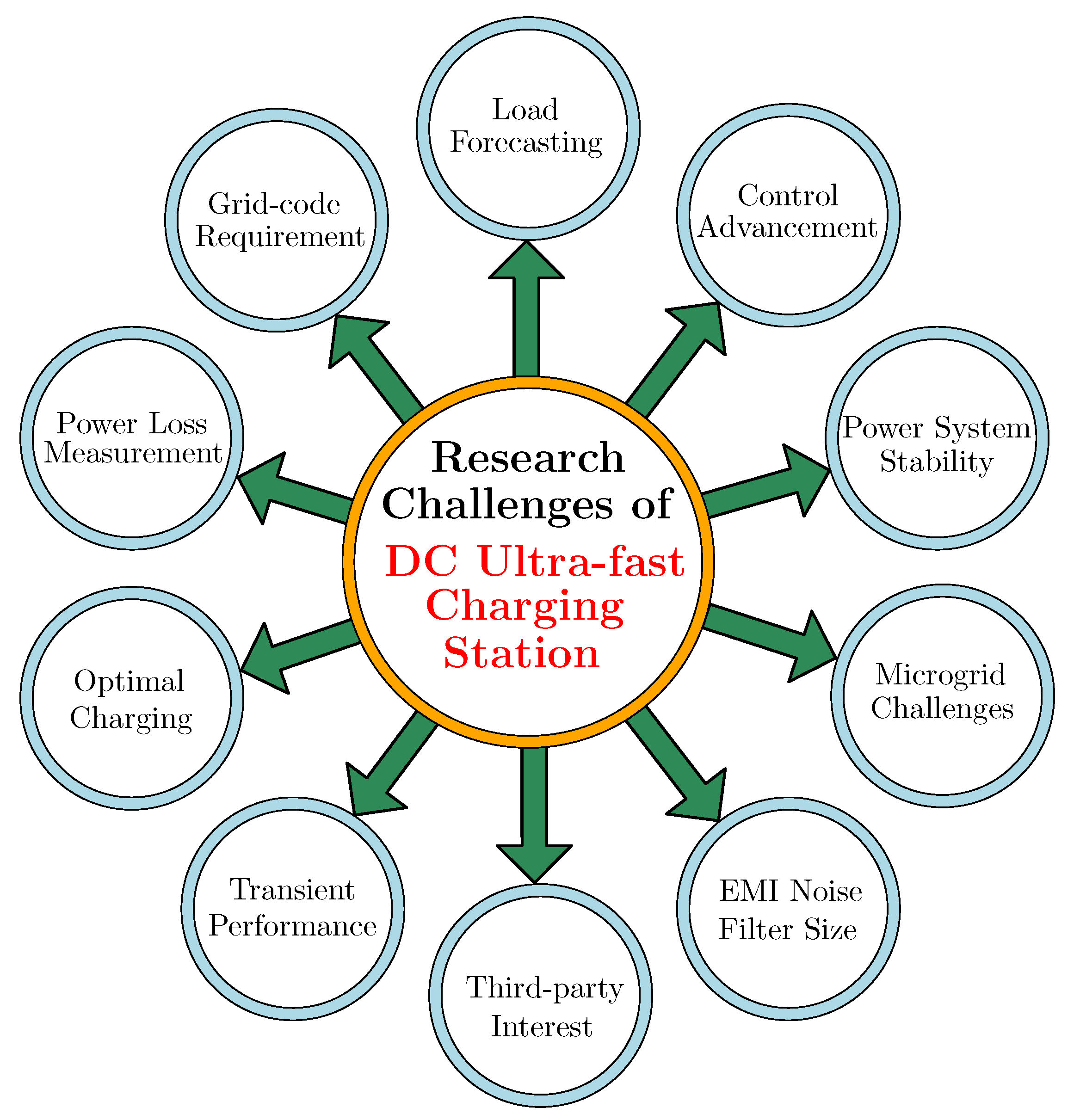
5. DC Ultra-Fast Charging Station Challenges and Research Gaps
In the vast adaptation of DC ultra-fast charging stations in the power grid, the important challenges are the increase in the daily peak load and shift, which may cause transformer and feeder overload, the power system devices’ deterioration due to aging, and the increase in power losses
[41]. Therefore, investigating the impact of high-power DC ultra-fast charging station load profiles in terms of power grid stability and proposing novel optimal charging strategies for the EV batteries are necessary. Moreover, from the power system operation point of view, the DC ultra-fast charging stations should be a controllable and predictable load. For that, different solutions have been proposed
[42]. One is integrating energy storage and renewable energies illustrated in the schematic shown in
Figure 1 with either AC-coupled or DC-coupled approaches proposed in
[3]. Indeed, such DC ultra-fast charging stations can be considered as AC/DC/Hybrid MGs with all their challenges
[43][44][45]. In order to increase the charging station third-party interests, the optimal sizing of the energy storage system is performed in
[46] through the station energy and storage cost reduction.
Due to the extensive use of power electronic converters, the main grid suffers hugely from power quality problems. Satisfying grid-code requirements could be another challenge in the high-power application for both flows of power. Proposing new converter topologies for the AC–DC and DC–DC power conversion stages with advanced control methods could solve this problem. In addition, it could add some advantages to the DC ultra-fast charging station, including modularity, bidirectional power flow capability, and higher efficiency in high-power applications. The optimum design of an input filter to reduce the size of the system and EMI effect is another important challenge. It should be noted that the different power converter topologies with various control methods could have different small-signal behaviors; therefore, the transient performance analysis of DC ultra-fast charging stations could be another open research area and needs more attraction.
In terms of DC-coupled ultra-fast charging stations, the safety issues need new definitions and structures
[47]. Furthermore, in the range of high-power transfer, the power loss during EV charging and discharging would increase due to the increase in the current value. Therefore, the measurement of power losses needs more attention
[48]. The challenges in the DC ultra-fast charging station are summarized in
Figure 3.
Figure 3. Research challenges in the DC ultra-fast charging stations.
Abbreviations
| AFE |
Active Front End |
| BMS |
Battery Management System |
| CHB |
Cascaded H-Bridge |
| DAB |
Dual Active Bridge |
| DAB-ANPC |
Dual Active Bridge-based Active Neutral Point Clamped |
| DHB |
Dual Half Bridge |
| EMI |
Electromagnetic Interference |
| EV |
Electrical Vehicle |
| FB |
Full Bridge |
| FC |
Flying Capacitor |
| HB |
Half Bridge |
| HT |
Hybrid Transformer |
| LFT |
Low Frequency Transformer |
| LLC-SRC |
LLC Series Resonant Converter |
| LVDC |
Low-Voltage DC |
| MCB |
Multi-Cell Boost |
| MG |
Microgrid |
| MMC |
Modular Multilevel Converter |
| MV |
Medium Voltage |
| NaNiCl |
Sodium Nickel Chloride |
| NiCd |
Nickel-Cadmium |
| NPC |
Neutral Point Clamped |
| PFC |
Power Factor Correction |
| PI |
Proportional Integral |
| PLL |
Phase Lock Loop |
| PR |
Proportional Resonant |
| PSFB |
Phase-Shifted Full-Bridge |
| PWM |
Pulse Width Modulated |
| QAB |
Quad Active Bridge |
| SiC |
Silicon Carbide |
| SMC |
Sliding-Mode Controller |
| SOC |
State of Charge |
| SOH |
State of Health |
| SPM |
Single Particle Model |
| SPMP |
Single-Phase Multi-Port |
| SST |
Solid-State Transformer |
| TLB |
Three-Level Boost |
| TLT |
Three-Level T-type |
| V2G |
Vehicle-to-Grid |
| V2H |
Vehicle-to-Home |
| V2V |
Vehicle-to-Vehicle |
| VR |
Vienna Rectifier |
 +1 credit