Your browser does not fully support modern features. Please upgrade for a smoother experience.
Submitted Successfully!
 +1 credit
Thank you for your contribution! You can also upload a video entry or images related to this topic.
For video creation, please contact our Academic Video Service.
Video Upload Options
We provide professional Academic Video Service to translate complex research into visually appealing presentations. Would you like to try it?
Cite
If you have any further questions, please contact Encyclopedia Editorial Office.
Xu, S.; Xue, Y.; Zhao, W.; Wan, D. High-Fidelity Computational Fluid Dynamics for Wind Turbines. Encyclopedia. Available online: https://encyclopedia.pub/entry/31686 (accessed on 27 June 2026).
Xu S, Xue Y, Zhao W, Wan D. High-Fidelity Computational Fluid Dynamics for Wind Turbines. Encyclopedia. Available at: https://encyclopedia.pub/entry/31686. Accessed June 27, 2026.
Xu, Shun, Yingjie Xue, Weiwen Zhao, Decheng Wan. "High-Fidelity Computational Fluid Dynamics for Wind Turbines" Encyclopedia, https://encyclopedia.pub/entry/31686 (accessed June 27, 2026).
Xu, S., Xue, Y., Zhao, W., & Wan, D. (2022, October 28). High-Fidelity Computational Fluid Dynamics for Wind Turbines. In Encyclopedia. https://encyclopedia.pub/entry/31686
Xu, Shun, et al. "High-Fidelity Computational Fluid Dynamics for Wind Turbines." Encyclopedia. Web. 28 October, 2022.
Copy Citation
The design and development of floating offshore wind turbines (FOWTs) is an attractive issue in the wind energy harvesting field. The FOWTs are considered more cost-effective than bottom-fixed offshore wind turbines in commercial operation with the significant technology advancements. However, several key factors for the design of FOWTs remain in need of more attention and effort. One of the key factors is the strong interaction between the wind turbine and floating platform. Unlike the bottom-fixed offshore wind turbines, the aerodynamics of FOWTs exhibits significant unsteady characteristics due to the floating platform motions excited by incident waves.
floating offshore wind turbines
computational fluid dynamics
fully coupled performance
actuator models
blade deformations
1. Introduction
In recent years, the development and utilization of offshore wind energy has become a burning issue and many dedicated efforts have focused on it, which has led to great advancements in offshore wind turbines in terms of scheme of design, build, operation and maintenance. Compared to the onshore wind energy harvesting, the benefits of offshore wind energy resources are obvious. For instance, abundant wind resources with higher wind speed and lower turbulence intensity, less constraints for space resources, and no visual and noise pollution, etc. [1]. The Global Wind Energy Council (GWEC) exhibits an outlook of new wind power installations for next five years (2022–2026), it is expected that the new installed offshore wind power in 2026 is 31.4 GW [2]. An increase of 48.8% compared to 21.1 GW in 2021 for offshore wind power is estimated, which is significantly higher than onshore wind power growth of 34.3%. If the good growth for offshore wind power continues, the global offshore wind power will reach up to 228 GW by 2030 and 1000 GW by 2050 [3].
The offshore wind turbines can be divided into two categories, bottom-fixed offshore wind turbines and floating offshore wind turbines (FOWTs). As their names suggest, the foundations of bottom-fixed offshore wind turbines are fixed in the seabed, while the support structures of offshore floating wind turbines are floating and connected to the seabed through mooring lines. One of the primary constraints for bottom-fixed offshore wind turbines is the applicability for water depth <60 m [4]. When the water depth >60 m (the deep water), the costs of construction and installation of bottom-fixed foundations increase intensely, which is not commercially applicable. However, more than 80% of offshore wind resources are available in sea area with depth >60 m. In order to address the cost issue of bottom-fixed wind turbines and pursue the capture of abundant wind resources in the deep-sea area, the FOWTs have been designed and developed.
The FOWTs can be divided into three major categories based on the types of supporting platforms, that are, spar buoy, semi-submersible and tension leg concepts [5][6], and sometimes also with a barge concept [7]. It is noteworthy that the mooring system can cause considerable costs due to the fact that the length of mooring lines is approximately 4 times the water depth. Moreover, the technology of FOWTs is comparatively immature than that of bottom-fixed offshore wind turbines. Consequently, the levelized cost of energy (LCOE) of FOWTs is unaffordable for full commercial utilization [8]. It is expected that the LCOE of bottom-fixed offshore wind turbines will decrease by 70% from 2015 to 2025, and the similar convergence trend will occur for FOWTs in 2030 [9].
In the foreseeable future, the FOWTs are considered more cost-effective than bottom-fixed offshore wind turbines in commercial operation with the significant technology advancements. However, several key factors for the design of FOWTs remain in need of more attention and effort. One of the key factors is the strong interaction between the wind turbine and floating platform. Unlike the bottom-fixed offshore wind turbines, the aerodynamics of FOWTs exhibits significant unsteady characteristics due to the floating platform motions excited by incident waves [10]. Additionally, the hydrodynamics of floating platforms is also significantly influenced by aerodynamic loads exerted on turbine rotors transmitted by the tower. Figure 1 shows the distributed flow field induced by the interactions between wind turbine and floating platform. It can be seen that the wind turbine is forced into and out of its wakes periodically due to the presence of the periodic pitch motion of floating platform, which will lead to the sophisticated characteristics of the aerodynamic power.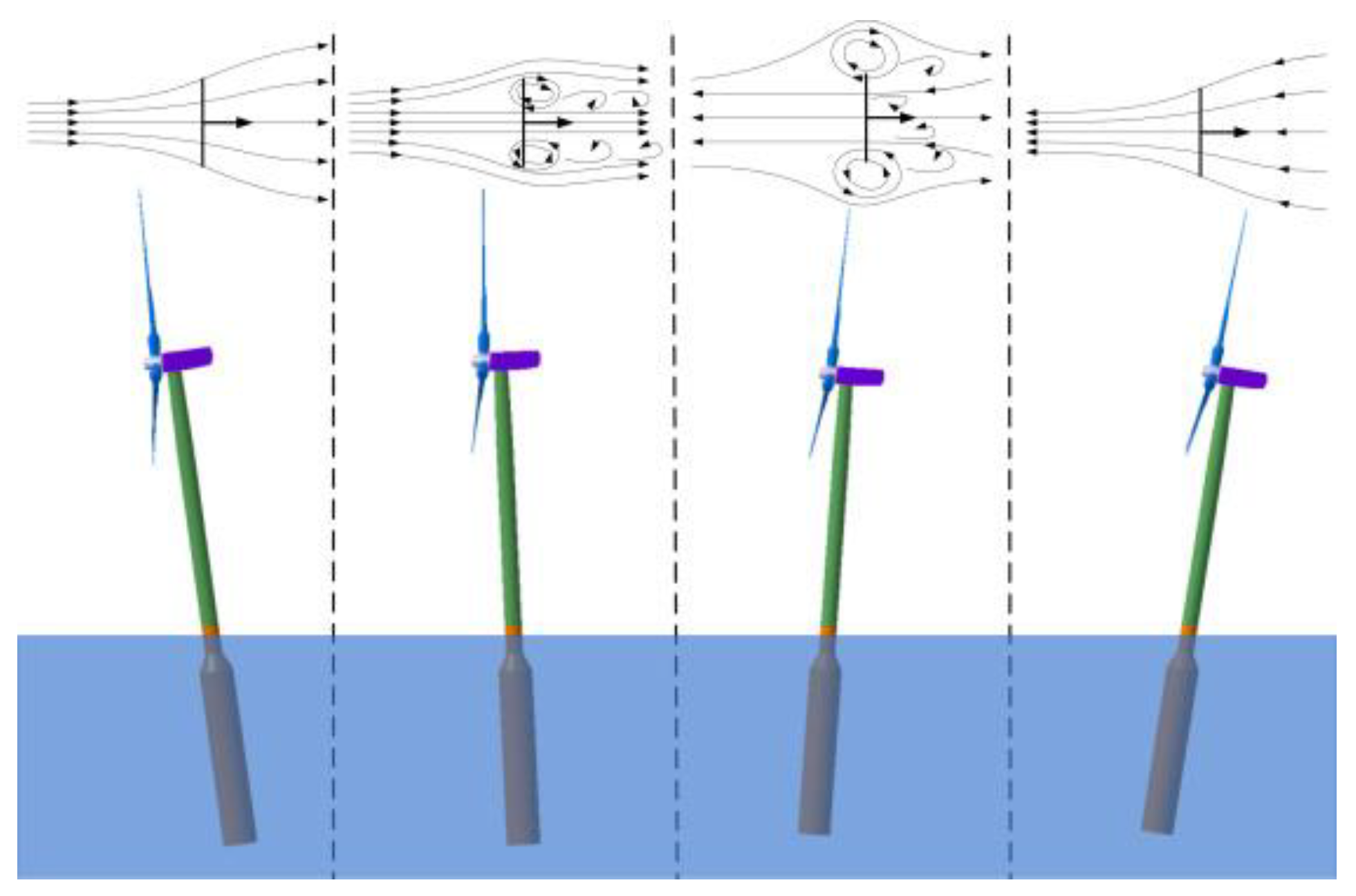
Figure 1. This disturbed flow field due to strong interactions of FOWT’s aero-hydrodynamics [11].
In addition to the strong interactions between aerodynamics and hydrodynamics of FOWTs, another key factor is the aeroelastic due to the notable feature of the increasing rotor diameter. As previously mentioned, the LCOE of FOWTs is more expansive than that of the onshore wind turbines. The technology advancements in rated power for offshore wind turbines will bring a considerable cost reduction, approximately 8.5%, and is significantly better than the advancements in aerodynamics and floating platform design and installation [12]. Consequently, the development trend of FOWTs towards a large size, with the aim to be more commercially affordable, which makes the aeroelastic responses of the wind turbine blades very prominent. It is known that the aerodynamic performance of wind turbines is reduced by the aeroelastic responses. Additionally, the issues of fatigue loads and structural failure for wind turbine blades are more urgent, particularly under severe sea conditions. Therefore, with the great advancements of FOWTs towards large-scale and deep-sea, the fully coupled aero-hydro-elastic performance requires a more systematic and comprehensive study to improve the reliability of FOWTs operated in combined wind-wave environments.
The research of the FOWTs is composed of three parts: the prototypes, the scale-down experiments and the numerical simulations, which are summarized in the previous literature reviews [13][14]. With the great advancements of high-performance computers (HPC), the numerical simulations for the FOWTs have gradually received a lot of attention. Some analysis codes have been developed and used [15][16]. Among those codes, the low-order modeling techniques incorporating the blade element momentum (BEM) theory [17] and potential flow (PF) models [5] are commonly employed in the design of FOWTs. Despite the low computational costs, those low-order modeling techniques cannot account for the viscous effects, which are important for calculating the aerodynamics of wind turbine blades, tower and hub, and the hydrodynamics of floating platform. Some correction models are required for BEM to guarantee the desired numerical results [18]. In other words, the ability of BEM on the predictions of aerodynamic loads needs further and comprehensive investigation [19], especially for FOWTs that the inflow wind conditions are more sophisticated due to the platform motions. In addition, the ability of potential-based models is limited on the accurate predictions of underlying flow mechanisms and its nonlinear dynamic characteristics, due to the fact that the flow separation around the platform cannot be captured [20]. In contrast, the above issues can be addressed by applying the high-fidelity computational fluid dynamics (CFD).
2. Component-Level Studies
2.1. Aerodynamics
In CFD-related simulations for wind turbine aerodynamics, two approaches exist: the actuator models, in which the wind turbine blades are represented by body force, and the direct modeling, in which the wind turbine blades are represented by computational and refined blade-resolved mesh. Representing wind turbine blades with actuator models has many advantages, for instance, avoiding solution of surface boundary layer of blades, saving the computational costs and easing the mesh generation. Generally, the actuator models are composed of three categories: actuator disk (AD), actuator line (AL) and actuator surface (AS), as shown in Figure 2. However, those actuator models are highly dependent on airfoil data, which is invalid for the design and development of novel wind turbine blades. By contrast, the direct blade-resolved modeling can easily handle this issue, and provide the rich and detailed flow field on the blade surface. Therefore, the two modeling methods are both widely used for the wind turbine aerodynamics.
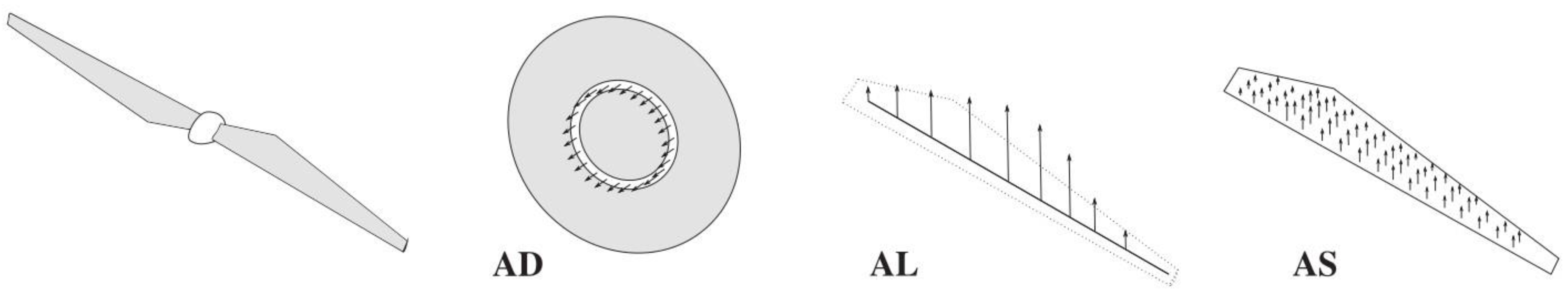
Figure 2. Three actuator models for wind turbine aerodynamics: AD, AL and AS [21].
2.1.1. Actuator Disk Model
For a uniformly loaded disk, the body force fAD exerts on disk surface can be expressed by
where, Vref is the reference velocity, CT is the thrust coefficient. It is important to note that the determination of reference velocity Vref is critical to calculate the thrust coefficient CT. Obviously, for an undisturbed uniform inflow, reference velocity Vref is evidently inflow velocity U∞. However, for the turbulent inflow situation, for instance, wakes of upstream wind turbines, this is not the case. This issue is usually addressed by introducing an iterative process based on the one-dimensional momentum theory [22], with it, the reference velocity Vref can be expressed by the function of axial induction a:
where, Vlocal is the local velocity of disk surface. Additionally, the body force for a non-uniformly loaded disk is also related with the radial position, but the body force over the annulus remains constant (see Figure 2). The sectional coefficients of lift and drag are used to calculate the body force of wind turbine blades. In addition to the uniform and non-uniform loads of actuator disk, the rotational effects are also taken into account by introducing the tangential forces [23].
Once the body force calculated by the AD are obtained, as well as AL and AS, a projection procedure is used to distribute the body force smoothly in the flow field, with the purpose of reflecting the effects of wind turbine blades on flow field and eliminating the numerical singularity. The Gauss smooth function is widely adopted for the smooth projection procedure, and a desired and reasonable projection width is approximately two times the mesh resolution around turbine blades [24]. Another iterative smooth projection function is the discrete Delta function, where less cells are required to satisfy the conservation of forces and moments [25].
Revaz and Porté-Agel [26] performed a comprehensive evaluation of AD compared with an experimental test, the effects of several factors, i.e., projection parameter, model formulation, hub, tower and grid resolution on wind turbine aerodynamics and wakes were analyzed. Their findings revealed that projection parameter has a strong effect in rotor plane and a lesser effect in streamwise direction. The effects of model formulation are evaluated by comparing the numerical results between a simple AD which the loads applied on rotor are uniform and an advanced AD which the loads are non-uniform and determined by blade element theory. Both models exhibit accurate predictions for thrust, power and wind turbine far wakes, but the advanced AD performs better in near wakes. In addition, the velocity deficit is enhanced and aerodynamic predictions are decreased due to the presence of hub and tower, which is referred to as the tower shadow effects. The calculation results reach convergence when less cells are arranged along the radial direction of the rotor, by approximately 10 cells. Furthermore, Micallef et al. [27] assessed the ability of non-uniform loaded AD for the predictions of near wake expansion, they importantly noted that the AD gives a reasonable prediction of wake expansion in the radially outboard positions, but exhibits a poor situation for mid-board and inboard areas. Li et al. [28] proposed a numerical model by incorporating the AD and an extended k-epsilon turbulence model, as well as considering the effects of hub and tower. By comparing with experimental data, the proposed model shows slightly better than the standard AD, the prediction accuracy in the near wake region is improved and the overall prediction accuracy for the wind turbine wakes is certainly promoted.
Some researchers also focus on the improvements of the AD, with the aim of achieving easier operation or more reasonable predictions. Sørensen et al. [29] proposed an analytical model for calculating the body forces of the AD, and the advantages of this model are that the detailed knowledge of wind turbines are not required, but only the rated wind speed and power capacity are needed. Conversely, Naderi et al. [30] employed an improved methodology for the AD to take into account all operational and geometrical characteristics of wind turbines, including airfoil type, angular velocity, twist, and chord distribution. Behrouzifar and Darbandi [31] developed an improved AD whereby the real thickness of wind turbine blades is considered, without the need to find the specific grid thickness of AD in the convergence tests, and thus the computational and temporal costs are reduced. Moreover, in order to consider the three-dimensional (3D) flow effects in radial direction, Amini et al. [32] introduced the 3D correction of aerodynamic coefficients into the AD. Compared to the original aerodynamic coefficients, the corrected 3D coefficients exhibit a better agreement with the experimental results.
2.2. Aeroelasticity
2.2.1. One-Dimensional Equilibrium Beam Model
The 1D EBM can be used efficiently to model the structures of wind turbine blades, owing to the slender characteristics of wind turbine blades. Roughly, the 1D EBM consists of two categories, linear beam models and nonlinear beam models. The Euler-Bernoulli beam model [33] and Timoshenko beam model [34] are the two widely used linear beam models. Compared to the Euler-Bernoulli beam model, the cross-sectional shear effects of turbine blades are accounted for the in the Timoshenko beam model. However, for the slender structures of turbine blades, the difference of the calculated deformations by the two beam models shows little distinction. The linear beam models have an assumption of small deformations, which is unreasonable and invalid for the wind turbines experience the situations of large deformations, such as the extreme wind conditions. Consequently, the nonlinear models have been proposed to consider the geometrically nonlinear characteristics of wind turbine blades and address the issue of large deformations. One of the well-known nonlinear beam models is the geometrically exact beam theory (GEBT) [35]. Except the rigid cross-sectional assumption, the GEBT does not contain other assumptions and the displacement-strain relationship can be used for significant displacement and rotation, which is suitable for the analysis of geometrically nonlinear beams.
Three discretization methods can be used to discretize the beam model into a series of beam elements, i.e., modal approach, MBD and 1D FEM. The modal approach is computationally efficient by representing the deformations of turbine blades based on the superposition of modes. Due to the linear superposition assumption of the modes, the modal approach is not appropriate for the large and nonlinear deformations of wind turbine blades, and the solution accuracy depends on the prescribed modal shapes. Additionally, the flutter analysis is excluded in modal approach because of the reduced degrees-of-freedom of beam elements. The MBD discretizes the blade structure into a series of independent beam elements, each of which is constrained by force or motion relationships. Compared to modal approach, the MBD suffers more computational costs, but the flutter analysis is considered and thus more accurate results are guaranteed [36]. The 1D FEM discretizes the blade into a series of beam elements that are connected through the internal force and displacement at the nodes, and solves the deformation in combination with boundary conditions. Among the three discretization methods, 1D FEM can more accurately describe blade deformations and a little more computational costs are required compared to the MBD. Consequently, the 1D FEM has been widely used in the aeroelastic analysis of wind turbine blades [37].
Gözcü and Verelst [38] studied the effects of fidelity levels of structure models on wind turbine load responses using the MBD and Timoshenko beam. The results showed that the load responses converge quickly to that of highest fidelity structure model with the increasing bodies, and indicated the significant effects of geometric nonlinearity for wind turbine blades. However, the low-fidelity BEM model was employed in the above study to calculate the wind turbine aerodynamics. For the certain and normal conditions, the low-fidelity BEM model combined with 1D structure model can capture correct aeroelastic responses for small wind turbines. However, for the situations of large wind turbines with significant blade tip deformations, the ability validation of those engineering models is of great needed and the high-fidelity models are suggested. Sayed et al. [39] evaluated the impacts of various fidelity levels of aerodynamic models on the aeroelasticity of DTU 10 MW wind turbine. The BEM model and CFD method incorporated with MBD solver SIMPACK were used, and Timoshenko beam was employed to represent the structures of rotor blades. It was found that the power and thrust predicted by the BEM-related aeroelastic model are smaller than that of CFD-related model. In addition, the effects of aerodynamic model fidelity are more pronounced for higher wind speeds. Li et al. [40] also presented a high-fidelity aero-servo-elastic framework for wind turbines by incorporating the CFD overset mesh technique and the MBD. The interactions between turbulence inflow, aeroelastic responses of turbine blades and the drivetrain dynamics were investigated. Similarly, Guma et al. [41] conducted a high-fidelity model for the aeroelastic responses of a 2 MW NM80 turbine subjected to turbulence inflow conditions by incorporating the CFD method for aerodynamics and the MBD for structure deformations. Different CFD modeling approaches with increasing complexity were performed to investigate its effects on wind turbine aeroelasticity. Grinderslev et al. [42] performed the aeroelastic simulations for a 2.3 MW wind turbine using CFD-based model with the MBD. Three inflow conditions, including the axisymmetric flow, the highly sheared flow and highly yawed-sheared flow, were employed. Their results were compared to BEM-MBD model and validated through field experiments. According to their analysis, the further validations of BEM-based model for complex flows are recommended through high-fidelity model.
Except the MBD-related models for aeroelastic analysis of wind turbine blades, some researchers have also focused on the 1D FEM-based models. Sayed et al. [43] conducted a high-fidelity CFD-CSD (computational structure dynamics) aeroelastic analysis for the DTU 10 MW wind turbine. The CFD solver FLOWer was utilized to calculate the aerodynamic loads and the CSD solver Carat++ was employed to predict the structure deformations based on the 1D FEM. Figure 3 shows the CFD surface mesh and CSD structure mesh. The numerical results reflected that the aerodynamic loads are reduced due to the aeroelastic deformations of turbine blades. Additionally, to investigate the coupling effects between aerodynamic models and structure models on the aeroelastic responses, the proposed CFD-CSD framework was compared with the CFD-MBD and BEM-MBD frameworks. Three years later, they presented a validated and comprehensive aeroelastic analysis based on the previous proposed framework [44]. The rotor power and thrust were enhanced due to the contribution of radial force induced by the edgewise deformations. The tower effects were discussed, in which the deformations and forces were decreased when blades passed the tower. Dose et al. [45] developed an aeroelastic tool for wind turbines by coupling CFD code OpenFOAM with the inhouse developed structure code BeamFOAM. The blade structures were represented by GEMT to account for the large deformations and discretized by finite elements. Their goal was to investigate how the blade deformations affect the wind turbine aerodynamic responses, i.e., rotor power, thrust, and cross-sectional forces. The results also demonstrated the same conclusion that the significant effects of blade aeroelasticity on aerodynamic response, especially for the yawed inflow conditions.
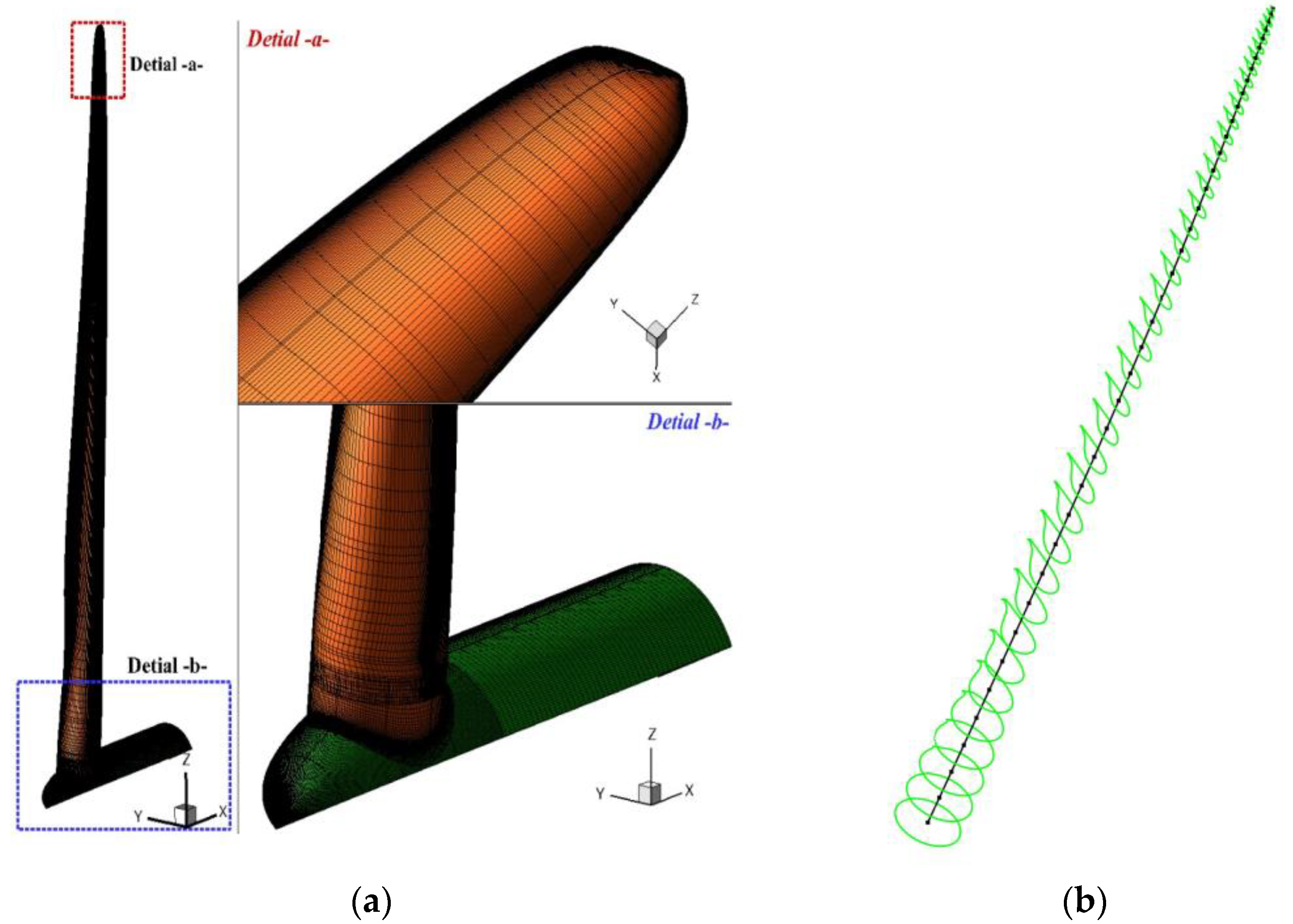
Figure 3. CFD-CSD mesh: (a) CFD surface mesh; (b) CSD beam finite elements (black lines), and the green sections are the predefined cross sections [43].
Due to the reasonable accuracy of the AL for wind turbine aerodynamics and its mature property, the turbine blade is regarded as a line which perfectly match the theory of the EBM, the AL-related aeroelastic analysis model has been developed and utilized recently for the aeroelasticity of wind turbines, namely the elastic actuator line (EAL). By combining the AL and a modal approach structure solver, Della et al. [46] presented an aeroelastic model for wind turbines. The distinction of one-way and two-way loose coupling methods between the fluid and structure solvers was discussed. Overpredicted results are found for rotor power and blade deformations when using the one-way coupling method, indicating the necessity of utilizing the two-way coupling method. Yu et al. [47] proposed a new EAL analysis model by combining the AL and 1D FEM to predict the aeroelastic responses of wind turbines rapidly. The influence of blade deformations and tower effects on wind turbine aerodynamic performance were examined and discussed. Moreover, the results indicated that the above effects on downstream wind turbine are more significant. Furthermore, Ma et al. [48] developed an aeroelastic framework for wind turbines based on the combination between the AL and the nonlinear beam model with finite elements. The study focused on the aeroelastic wake behaviors of NREL 5 MW wind turbine and found that the vorticity and velocity recovery in far wakes are underpredicted due to the absence of blade deformations. Meng et al. [49][50] examined the fatigue loads on downstream wind turbines by the EAL model. The complex atmospheric inflow was considered, and two in-line wind turbines and a wind farm with nine wind turbines were performed. A significant enhanced fatigue damage for downstream wind turbines was discovered, compared to that of upstream wind turbines.
2.2.2. Three-Dimensional Finite Element Method
The required accuracy of aeroelastic responses for wind turbines has a great impact on the selected structure models. To pursue more precise and detailed results of wind turbines, the 3D nonlinear FEM is a more suitable option. The 3D FEM structure models are broadly divided into two categories [51], the shell element model and the solid element model, as shown in Figure 4. The shell element model is usually used to predict the cross-sectional deformations of turbine blades. However, if the detailed stress or damage estimation of turbine blades are desired, the solid element model is commonly adopted.
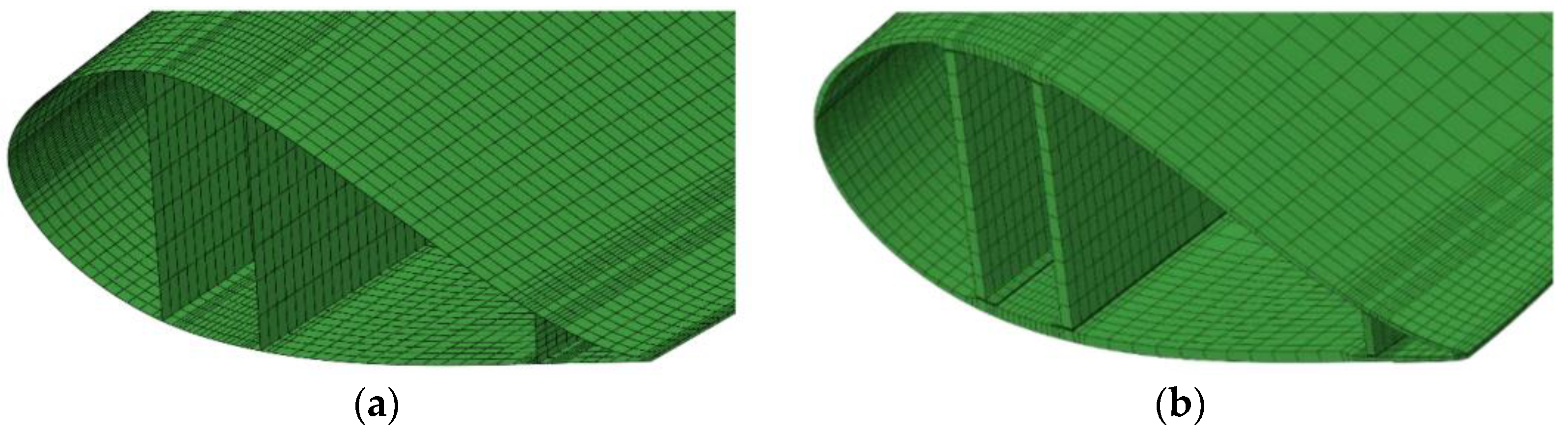
Figure 4. The 3D FEM structure models: (a) shell element model; (b) solid element model [52].
To handle the aeroelastic design of a high power wind turbine, Tojo and Marta [53] developed a fluid-structure interaction (FSI) solver in OpenFOAM. The blade structures were represented by solid hexahedral elements and the blade rotation was addressed by a single rotating framework. They noted that the aeroelastic responses of wind turbines is definitely a problem and should be considered when the turbine size increases. Zhangaskanov et al. [54] performed an investigation of the aeroelastic performance of NREL Phase VI wind turbine based on a FSI solver, which is also implemented in OpenFOAM. The turbine blade structures were represented by the solid element model. The simulation results showed a good agreement with experiments, outlining the accurate prediction ability of the high-fidelity CFD-CSD framework for aeroelastic analysis of wind turbines. Peeters et al. [52] studied the structure deformations of a wind turbine blade under static loads, both the shell element model and the solid element model were used to model the wind turbine blade. Compared to the experiment measurements, the differences of the two models were minor, reflecting the sufficient prediction accuracy of blade structure deformations under the specific load case for the shell element model.
Similar with the comparison between the solid and shell element models, Guma et al. [55] conducted a comparison between the beam model and the shell element model for the aeroelastic analysis of a small wind turbine by applying the coupling between the CFD solver FLOWer and the FEM solver Kratos. The results indicated that the beam model is sufficient to predict the blade deformations for a wind turbine blade under uniform inflow conditions. However, when the complexity of simulation cases increased, i.e., the full wind turbine under turbulent inflow conditions, the shell element model is required to give more reasonable results. Shkara et al. [56] investigated the interactions between elastic blades and tower by combining a CFD solver and a FEM solver. The structure of blades and tower were discretized through shell element model. It was concluded that the rotor azimuthal position has a significant effect on the structure dynamic responses of tower. Additionally, they also performed the same simulations using the BEM-MBD aeroelastic framework, and higher flapwise and edgewise deformations of turbine blades were predicted. Apart from the rotor-tower interaction, Santo et al. [57] also presented the effects of tilt angle and yaw misalignment on the aeroelastic performance of wind turbines. They observed that the blade deformations are significantly affected by tilt angle due to its contribution to gravity, and a reduction in blade axial displacement is observed.
References
- Esteban, M.D.; Diez, J.J.; López, J.S.; Negro, V. Why offshore wind energy? Renew. Energy 2011, 36, 444–450.
- Global Wind Report 2022. Available online: https://gwec.net/global-wind-report-2022/ (accessed on 10 July 2022).
- Future of Wind. Available online: https://www.irena.org/publications/2019/Oct/Future-of-wind (accessed on 10 July 2022).
- Asim, T.; Islam, S.Z.; Hemmati, A.; Khalid, M.S.U. A review of recent advancements in offshore wind turbine technology. Energies 2022, 15, 579.
- Bashetty, S.; Ozcelik, S. Review on Dynamics of Offshore Floating Wind Turbine Platforms. Energies 2021, 14, 6026.
- Musial, W. Overview of Floating Offshore Wind; National Renewable Energy Laboratory: Golden, CO, USA, 2020.
- Jiang, Z. Installation of offshore wind turbines: A technical review. Renew. Sust. Energ. Rev. 2021, 139, 110576.
- Martinez, A.; Iglesias, G. Mapping of the levelised cost of energy for floating offshore wind in the European Atlantic. Renew. Sust. Energ. Rev. 2022, 154, 111889.
- Wiser, R.; Rand, J.; Seel, J.; Beiter, P.; Baker, E.; Lantz, E.; Gilman, P. Expert elicitation survey predicts 37% to 49% declines in wind energy costs by 2050. Nat. Energy 2021, 6, 555–565.
- Matha, D.; Schlipf, M.; Pereira, R.; Jonkman, J. Challenges in simulation of aerodynamics, hydrodynamics, and mooring-line dynamics of floating offshore wind turbines. In Proceedings of the Twenty-First International Offshore and Polar Engineering Conference, Maui, HI, USA, 19–24 June 2011.
- Tran, T.T.; Kim, D.H. The platform pitching motion of floating offshore wind turbine: A preliminary unsteady aerodynamic analysis. J. Wind Eng. Ind. Aerodyn. 2015, 142, 65–81.
- Röckmann, C.; Lagerveld, S.; Stavenuiter, J. Operation and Maintenance Costs of Offshore Wind Farms and Potential Multi-Use Platforms in the Dutch North Sea. In Aquaculture Perspective of Multi-Use Sites in the Open Ocean; Springer: Cham, Switzerland, 2017; pp. 97–113.
- Otter, A.; Murphy, J.; Pakrashi, V.; Robertson, A.; Desmond, C. A review of modelling techniques for floating offshore wind turbines. Wind Energy 2022, 25, 831–857.
- Chen, P.; Chen, J.; Hu, Z. Review of Experimental-Numerical Methodologies and Challenges for Floating Offshore Wind Turbines. J. Mar. Sci. Eng. Appl. 2020, 19, 339–361.
- Guo, X.; Zhang, Y.; Yan, J.; Zhou, Y.; Yan, S.; Shi, W.; Li, X. Integrated Dynamics Response Analysis for IEA 10-MW Spar Floating Offshore Wind Turbine. J. Mar. Sci. Eng. 2022, 10, 542.
- Zhang, H.; Wang, H.; Cai, X.; Xie, J.; Wang, Y.; Zhang, N. Research on the Dynamic Performance of a Novel Floating Offshore Wind Turbine Considering the Fully-Coupled-Effect of the System. J. Mar. Sci. Eng. 2022, 10, 341.
- Chen, J.; Hu, Z.; Liu, G.; Wan, D. Coupled aero-hydro-servo-elastic methods for floating wind turbines. Renew. Energy 2019, 130, 139–153.
- Madsen, H.A.; Bak, C.; Døssing, M.; Mikkelsen, R.; Øye, S. Validation and modification of the blade element momentum theory based on comparisons with actuator disc simulations. Wind Energy 2010, 13, 373–389.
- Sebastian, T.; Lackner, M. Characterization of the unsteady aerodynamics of offshore floating wind turbines. Wind Energy 2013, 16, 339–352.
- Oguz, E.; Clelland, D.; Day, A.H.; Incecik, A.; López, J.A.; Sánchez, G.; Almeria, G.G. Experimental and numerical analysis of a TLP floating offshore wind turbine. Ocean Eng. 2018, 147, 591–605.
- Sanderse, B.; Van der Pijl, S.P.; Koren, B. Review of computational fluid dynamics for wind turbine wake aerodynamics. Wind Energy 2011, 14, 799–819.
- Prospathopoulos, J.M.; Politis, E.S.; Rados, K.G.; Chaviaropoulos, P.K. Enhanced CFD modelling of wind turbine wakes. In Proceedings of the Wind Turbine Wakes, Madrid, Spain, 20–22 October 2009.
- Wu, Y.T.; Porté-Agel, F. Large-eddy simulation of wind-turbine wakes: Evaluation of turbine parametrisations. Bound. Layer Meteor. 2011, 138, 345–366.
- Troldborg, N. Actuator Line Modeling of Wind Turbine Wakes. Ph.D. Thesis, Technical University of Denmark, Lyngby, Denmark, 2009.
- Yang, X.; Zhang, X.; Li, Z.; He, G.W. A smoothing technique for discrete delta functions with application to immersed boundary method in moving boundary simulations. J. Comput. Phys. 2009, 228, 7821–7836.
- Revaz, T.; Porté-Agel, F. Large-Eddy Simulation of Wind Turbine Flows: A New Evaluation of Actuator Disk Models. Energies 2021, 14, 3745.
- Micallef, D.; Ferreira, C.; Herráez, I.; Höning, L.; Yu, W.; Capdevila, H. Assessment of actuator disc models in predicting radial flow and wake expansion. J. Wind Eng. Ind. Aerodyn. 2020, 207, 104396.
- Li, N.; Liu, Y.; Li, L.; Chang, S.; Han, S.; Zhao, H.; Meng, H. Numerical simulation of wind turbine wake based on extended k-epsilon turbulence model coupling with actuator disc considering nacelle and tower. IET Renew. Power Gener. 2020, 14, 3834–3842.
- Sørensen, J.N.; Nilsson, K.; Ivanell, S.; Asmuth, H.; Mikkelsen, R.F. Analytical body forces in numerical actuator disc model of wind turbines. Renew. Energy 2020, 147, 2259–2271.
- Naderi, S.; Parvanehmasiha, S.; Torabi, F. Modeling of horizontal axis wind turbine wakes in Horns Rev offshore wind farm using an improved actuator disc model coupled with computational fluid dynamic. Energy Conv. Manag. 2018, 171, 953–968.
- Behrouzifar, A.; Darbandi, M. An improved actuator disc model for the numerical prediction of the far-wake region of a horizontal axis wind turbine and its performance. Energy Conv. Manag. 2019, 185, 482–495.
- Amini, S.; Golzarian, M.R.; Mahmoodi, E.; Jeromin, A.; Abbaspour-Fard, M.H. Numerical simulation of the Mexico wind turbine using the actuator disk model along with the 3D correction of aerodynamic coefficients in OpenFOAM. Renew. Energy 2021, 163, 2029–2036.
- Bauchau, O.A.; Craig, J.I. Euler-Bernoulli Beam Theory. Structural Analysis; Springer: Dordrecht, The Netherlands, 2009; pp. 173–221.
- Oñate, E. Structural Analysis with the Finite Element Method. In Linear Statics: Volume 2: Beams, Plates and Shells; Springer Science & Business Media: Berlin, Germany, 2013.
- Hodges, D.H. Geometrically exact, intrinsic theory for dynamics of curved and twisted anisotropic beams. AIAA J. 2003, 41, 1131–1137.
- Shabana, A. Dynamics of Multibody Systems; Cambridge University Press: Cambridge, UK, 2020.
- Hansen, M.O.L.; Sørensen, J.N.; Voutsinas, S.; Sørensen, N.; Madsen, H.A. State of the art in wind turbine aerodynamics and aeroelasticity. Prog. Aeosp. Sci. 2006, 42, 285–330.
- Gözcü, O.; Verelst, D.R. The effects of blade structural model fidelity on wind turbine load analysis and computation time. Wind Energy Sci. 2020, 5, 503–517.
- Sayed, M.; Klein, L.; Lutz, T.; Krämer, E. The impact of the aerodynamic model fidelity on the aeroelastic response of a multi-megawatt wind turbine. Renew. Energy 2019, 140, 304–318.
- Li, Y.; Castro, A.M.; Martin, J.E.; Sinokrot, T.; Prescott, W.; Carrica, P.M. Coupled computational fluid dynamics/multibody dynamics method for wind turbine aero-servo-elastic simulation including drivetrain dynamics. Renew. Energy 2017, 101, 1037–1051.
- Guma, G.; Bangga, G.; Lutz, T.; Krämer, E. Aeroelastic analysis of wind turbines under turbulent inflow conditions. Wind Energy Sci. 2021, 6, 93–110.
- Grinderslev, C.; González Horcas, S.; Sørensen, N.N. Fluid–structure interaction simulations of a wind turbine rotor in complex flows, validated through field experiments. Wind Energy 2021, 24, 1426–1442.
- Sayed, M.; Lutz, T.; Krämer, E.; Shayegan, S.; Ghantasala, A.; Wüchner, R.; Bletzinger, K.U. High fidelity CFD-CSD aeroelastic analysis of slender bladed horizontal-axis wind turbine. J. Phys. Conf. Ser. 2016, 753, 042009.
- Sayed, M.; Lutz, T.; Krämer, E.; Shayegan, S.; Wüchner, R. Aeroelastic analysis of 10 MW wind turbine using CFD–CSD explicit FSI-coupling approach. J. Fluids Struct. 2019, 87, 354–377.
- Dose, B.; Rahimi, H.; Herráez, I.; Stoevesandt, B.; Peinke, J. Fluid-structure coupled computations of the NREL 5 MW wind turbine by means of CFD. Renew. Energy 2018, 129, 591–605.
- Della Posta, G.; Leonardi, S.; Bernardini, M. A two-way coupling method for the study of aeroelastic effects in large wind turbines. Renew. Energy 2022, 190, 971–992.
- Yu, Z.; Hu, Z.; Zheng, X.; Ma, Q.; Hao, H. Aeroelastic performance analysis of wind turbine in the wake with a new Elastic Actuator Line model. Water 2020, 12, 1233.
- Ma, Z.; Zeng, P.; Lei, L. Analysis of the coupled aeroelastic wake behavior of wind turbine. J. Fluids Struct. 2019, 84, 466–484.
- Meng, H.; Lien, F.S.; Glinka, G.; Li, L.; Zhang, J. Study on wake-induced fatigue on wind turbine blade based on elastic actuator line model and two-dimensional finite element model. Wind Eng. 2019, 43, 64–82.
- Meng, H.; Li, L.; Zhang, J. A preliminary numerical study of the wake effects on the fatigue load for wind farm based on elastic actuator line model. Renew. Energy 2020, 162, 788–801.
- Sayed, M.; Bucher, P.; Guma, G.; Lutz, T.; Wüchner, R. Aeroelastic Simulations Based on High-Fidelity CFD and CSD Models. In Handbook of Wind Energy Aerodynamics; Springer: Cham, Switzerland, 2022; pp. 1–76.
- Peeters, M.; Santo, G.; Degroote, J.; Van Paepegem, W. Comparison of shell and solid finite element models for the static certification tests of a 43 m wind turbine blade. Energies 2018, 11, 1346.
- Tojo, B.M.; Marta, A.C. Aero-Structural blade design of a high-power wind turbine. In Proceedings of the 54th AIAA/ASME/ASCE/AHS/ASC Structures, Structural Dynamics, and Materials Conference, Boston, MA, USA, 8–11 April 2013.
- Zhangaskanov, D.; Batay, S.; Kamalov, B.; Zhao, Y.; Su, X.; Ng, E.Y.K. High-Fidelity 2-Way FSI Simulation of a Wind Turbine Using Fully Structured Multiblock Meshes in OpenFoam for Accurate Aero-Elastic Analysis. Fluids 2022, 7, 169.
- Guma, G.; Bucher, P.; Letzgus, P.; Lutz, T.; Wüchner, R. High-fidelity aeroelastic analyses of wind turbines in complex terrain: Fluid–structure interaction and aerodynamic modeling. Wind Energy Sci. 2022, 7, 1421–1439.
- Shkara, Y.; Cardaun, M.; Schelenz, R.; Jacobs, G. Aeroelastic response of a multi-megawatt upwind horizontal axis wind turbine (HAWT) based on fluid–structure interaction simulation. Wind Energy Sci. 2020, 5, 141–154.
- Santo, G.; Peeters, M.; Van Paepegem, W.; Degroote, J. Effect of rotor–tower interaction, tilt angle, and yaw misalignment on the aeroelasticity of a large horizontal axis wind turbine with composite blades. Wind Energy 2020, 23, 1578–1595.
More
Information
Subjects:
Engineering, Ocean
Contributors
MDPI registered users' name will be linked to their SciProfiles pages. To register with us, please refer to https://encyclopedia.pub/register
:
View Times:
1.3K
Revisions:
2 times
(View History)
Update Date:
31 Oct 2022
Table of Contents


Notice
You are not a member of the advisory board for this topic. If you want to update advisory board member profile, please contact office@encyclopedia.pub.
OK
Confirm
Only members of the Encyclopedia advisory board for this topic are allowed to note entries. Would you like to become an advisory board member of the Encyclopedia?
Yes
No
${ textCharacter }/${ maxCharacter }
Submit
Cancel
Back
Comments
${ item }
|
${ item.createdUser.fullName }
${ item.createdAt }
${ item.vote }
${ item.reply }
Delete
${ reply.createdUser.fullName }
${ reply.createdAt }
${ reply.vote }
Delete
There is no reply to this comment~
${ item.replyTextCharacter }/${ item.replyMaxCharacter }
Submit
Cancel
More
No more~
There is no comment~
${ textCharacter }/${ maxCharacter }
Submit
Cancel
${ selectedItem.replyTextCharacter }/${ selectedItem.replyMaxCharacter }
Submit
Cancel
Confirm
Are you sure to Delete?
Yes
No