Your browser does not fully support modern features. Please upgrade for a smoother experience.
Submitted Successfully!
 +1 credit
Thank you for your contribution! You can also upload a video entry or images related to this topic.
For video creation, please contact our Academic Video Service.
| Version | Summary | Created by | Modification | Content Size | Created at | Operation |
|---|---|---|---|---|---|---|
| 1 | Pradeep Kumar | -- | 4340 | 2022-10-26 18:15:26 | | | |
| 2 | Peter Tang | -3 word(s) | 4337 | 2022-10-27 06:10:26 | | |
Video Upload Options
We provide professional Academic Video Service to translate complex research into visually appealing presentations. Would you like to try it?
Cite
If you have any further questions, please contact Encyclopedia Editorial Office.
Sharma, P.; Tiwari, R.N.; Singh, P.; Kumar, P.; Kanaujia, B.K. MIMO Antennas for 5G and 6G Wireless Systems. Encyclopedia. Available online: https://encyclopedia.pub/entry/31461 (accessed on 18 July 2026).
Sharma P, Tiwari RN, Singh P, Kumar P, Kanaujia BK. MIMO Antennas for 5G and 6G Wireless Systems. Encyclopedia. Available at: https://encyclopedia.pub/entry/31461. Accessed July 18, 2026.
Sharma, Preeti, Rakesh N. Tiwari, Prabhakar Singh, Pradeep Kumar, Binod K. Kanaujia. "MIMO Antennas for 5G and 6G Wireless Systems" Encyclopedia, https://encyclopedia.pub/entry/31461 (accessed July 18, 2026).
Sharma, P., Tiwari, R.N., Singh, P., Kumar, P., & Kanaujia, B.K. (2022, October 26). MIMO Antennas for 5G and 6G Wireless Systems. In Encyclopedia. https://encyclopedia.pub/entry/31461
Sharma, Preeti, et al. "MIMO Antennas for 5G and 6G Wireless Systems." Encyclopedia. Web. 26 October, 2022.
Copy Citation
Multiple-input multiple-output (MIMO) antennas are getting more attention in modern high-speed communication systems and play an essential part in the current generation of wireless technology. Portable devices, automobiles, handheld gadgets, smart phones, wireless sensors, radio frequency identification and other applications use MIMO antenna systems.
MIMO antennas
dual-band
circularly polarized MIMO antennas
isolation techniques
diversity parameters
5G technology
1. Introduction
Due to the usage of internet platforms in a variety of areas, wireless systems with high data rates and adequate channel capacity are in great demand. These requirements are usually incompatible with single-input and single-output (SISO) antennas. As a result, multiple-input and multiple-output (MIMO) printed antennas, a new form of antenna design, has emerged as a suitable candidate for high-speed communication technologies [1][2]. In such designs, two or more radiating elements are fed separately using a coplanar or strip line feeding technique to transmit and receive the data. However, the coupling between the ports is a major concern in MIMO design because it degrades the performance of MIMO antennas. As a result, several attempts have been undertaken to increase the isolation between the radiators. One of the ways to achieve good isolation in MIMO antennas is to use a metamaterial-based MIMO design [3][4]. For better decoupling, a suspended meta-surface made up of periodic square split-ring resonators (SRRs) are placed above the antenna array [5]. A split ring comprising an inductive line and a capacitive gap to achieve magnetic and electric coupling, respectively, is used to build the decoupling structure [6]. The orthogonally structured MIMO antenna provides excellent isolation [7][8]. In MIMO systems, latency can be reduced by massive MIMO configurations [9]. Rectangular strip based decoupling structure is used for isolation improvements [10]. A well-designed defective ground structure (DGS) along with the decoupling conducting strip printed between the radiating elements decreases the mutual coupling [11]. The theory of characteristic modes is also used for MIMO antenna systems in order to build a systematic technique to predict the isolation improvement [12]. With the advent of ultra-compact circuits, the isolation between each terminal of a MIMO system becomes crucial in order to achieve high system accuracy [13][14].
2. MIMO Antenna Design Approaches
MIMO antennas have received much attention in the modern wireless communication system as it can use multi-paths to transmit or receive data, and hence increase the range and output performance [15]. It is noted that the significant isolation between components of the same MIMO system is necessary so that elements of the MIMO antenna can work independently to transmit or receive signals simultaneously without deteriorating the antenna parameters.
In order to ensure the quality of a MIMO antenna, in addition to S-parameters and radiation characteristics, certain diversity parameters are used. The MIMO antennas must satisfy the predefined values of the diversity parameters for practical applications.
3. Ultra-Wideband (UWB) MIMO Antenna Designs
Ultra-wideband (UWB or digital pulse wireless) is a radio-based wireless communication technology that allows the transmission of a huge amount of digital data over a broad range of frequency bands with extremely little power over short distances. In this section, the different UWB MIMO antennas are reported which includes modification in the radiating patches, ground plane (GP) and isolation techniques (Figure 1). UWB technology offers a frequency range of 3.1 to 10.6 GHz with channel bandwidths of more than 500 MHz [16]. For the decoupling of a small UWB MIMO antenna, a broadband neutralized line is employed [17]. With a mutual coupling of less than −22 dB, this UWB MIMO antenna has covered the lower UWB range of 3.1–5 GHz. MIMO designs must display wideband features to meet the demands of increased spectral efficiency, provided that the reciprocal coupling between the radiating components is kept to a minimum [17][18][19]. The decoupling network using two inverters and two connected split-ring resonators (SRRs) in [20] provides excellent isolation between the ports.
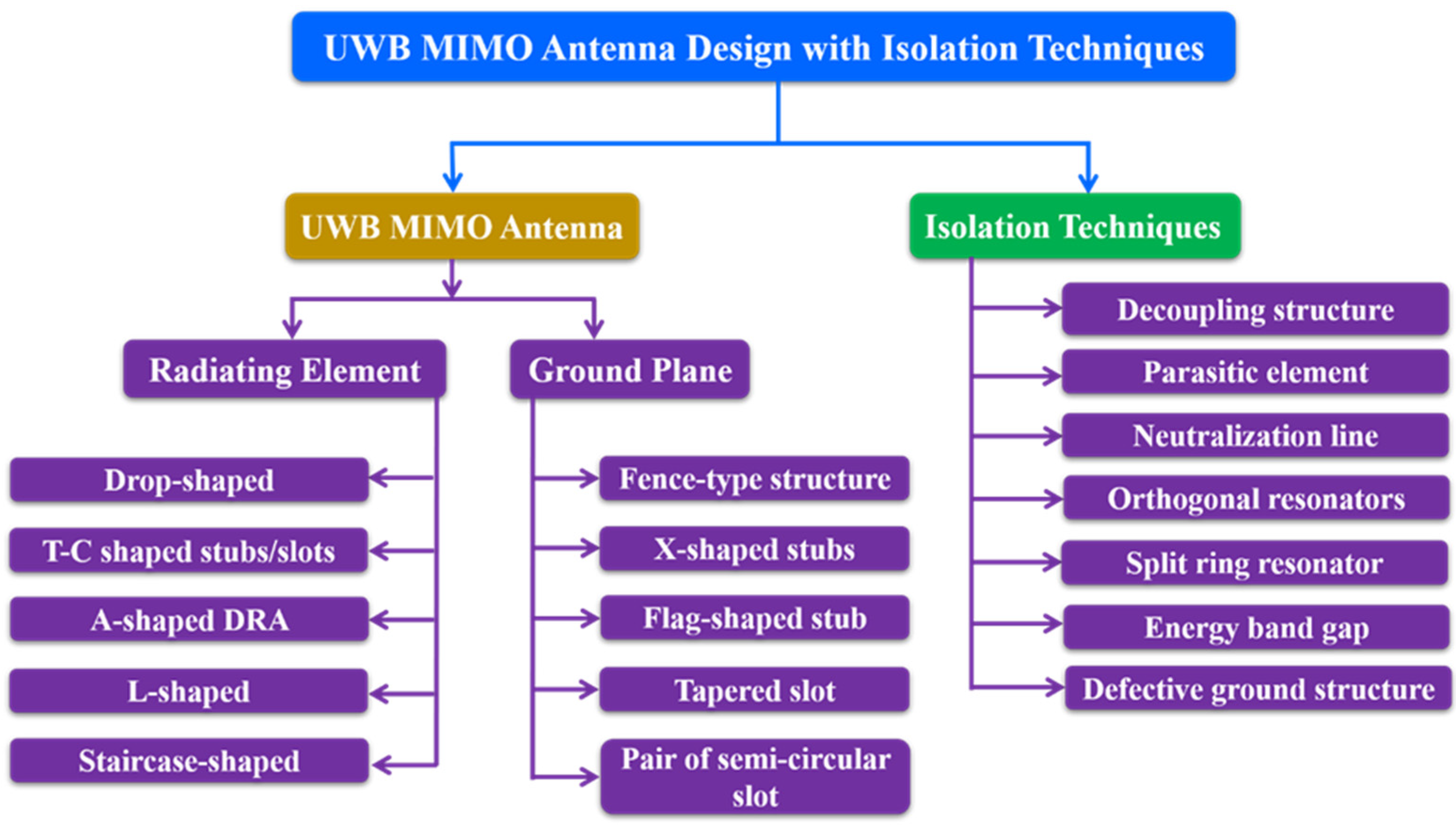
Figure 1. Typical UWB MIMO antenna design approaches.
A four-element compact MIMO antenna with a total volume of 26 × 26 × 0.8 mm3 and a 4 mm edge-to-edge distance between the radiating patches is reported in [21]. A groove is carved in the center of the GP (Figure 2) to prevent mutual coupling. The MIMO antenna functions with isolation of more than 15.4 dB in the frequency region from 5.6 to 5.8 GHz (Figure 3). The maximum achieved gain for this antenna is >1.41 dBi across the applicable band and can be implemented in portable devices for WLAN applications at 5.7 GHz.
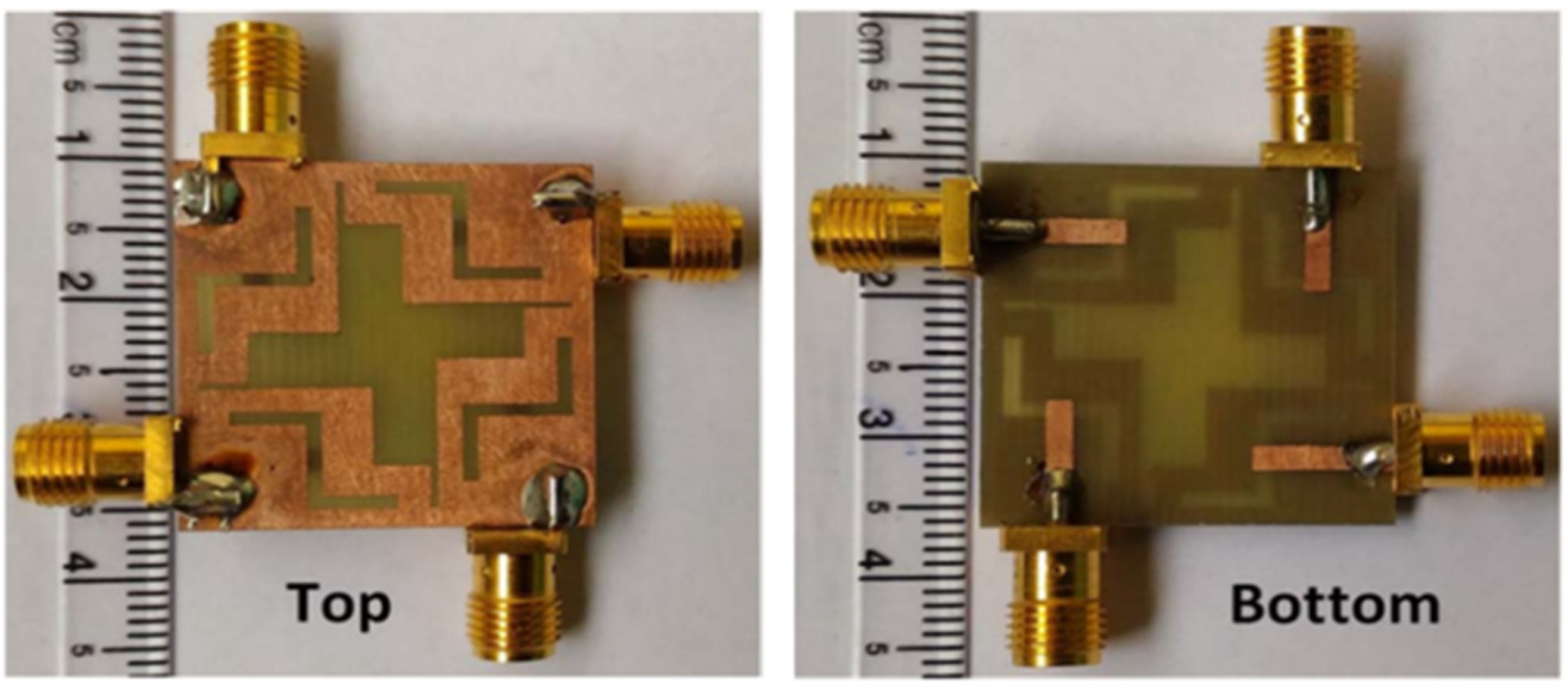
Figure 2. The fabricated prototype of 4 × 4 MIMO antenna [21]. (Left side: ground plane and right side: microstrip line).
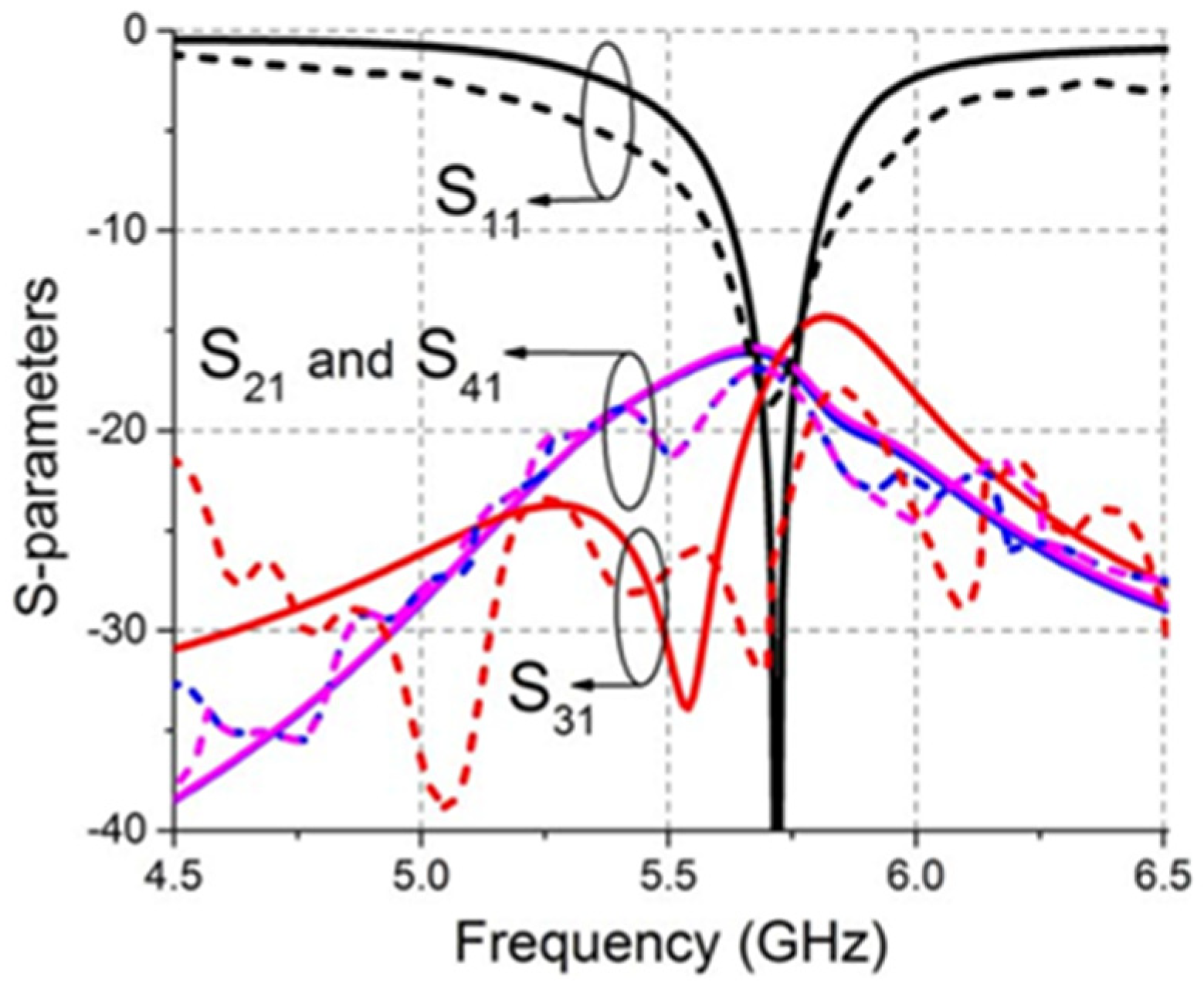
Figure 3. S–parameters of the MIMO antenna. — simulated and --- measured [21].
Figure 4 shows the structure of the 4 × 4 UWB MIMO antenna as reported in [22]. The dimensions of the reported antenna is 48 × 34 × 1.6 mm3. The MIMO design consists of the rectangular patch attached with a half-circular disc of radius 4.8 mm. The lower corners of the rectangular patch are carved with a small amount of copper to achieve UWB characteristics. The neutralization line connects the two symmetrical antennas to increase the isolation between the two radiating patches. The corresponding S-parameters are plotted and presented in Figure 5. The observed bandwidth and isolation of 2 × 2 and 4 × 4 MIMO antennas are 95.22% (3.51–9.89 GHz) and −24 dB, and 96.47% (3.52–10.08 GHz) and −23 dB, respectively.
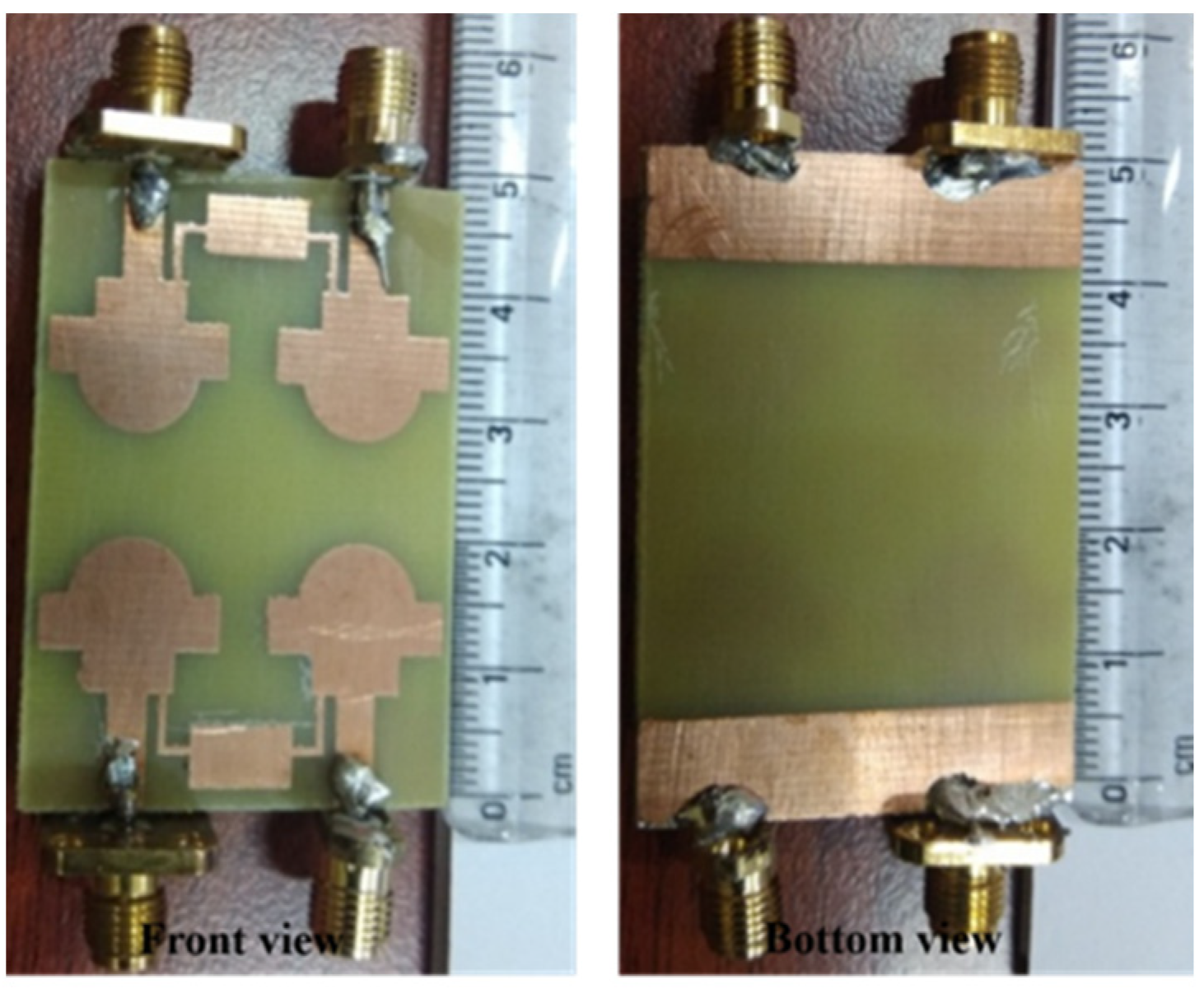
Figure 4. Fabricated 4 × 4 MIMO antenna design [22].
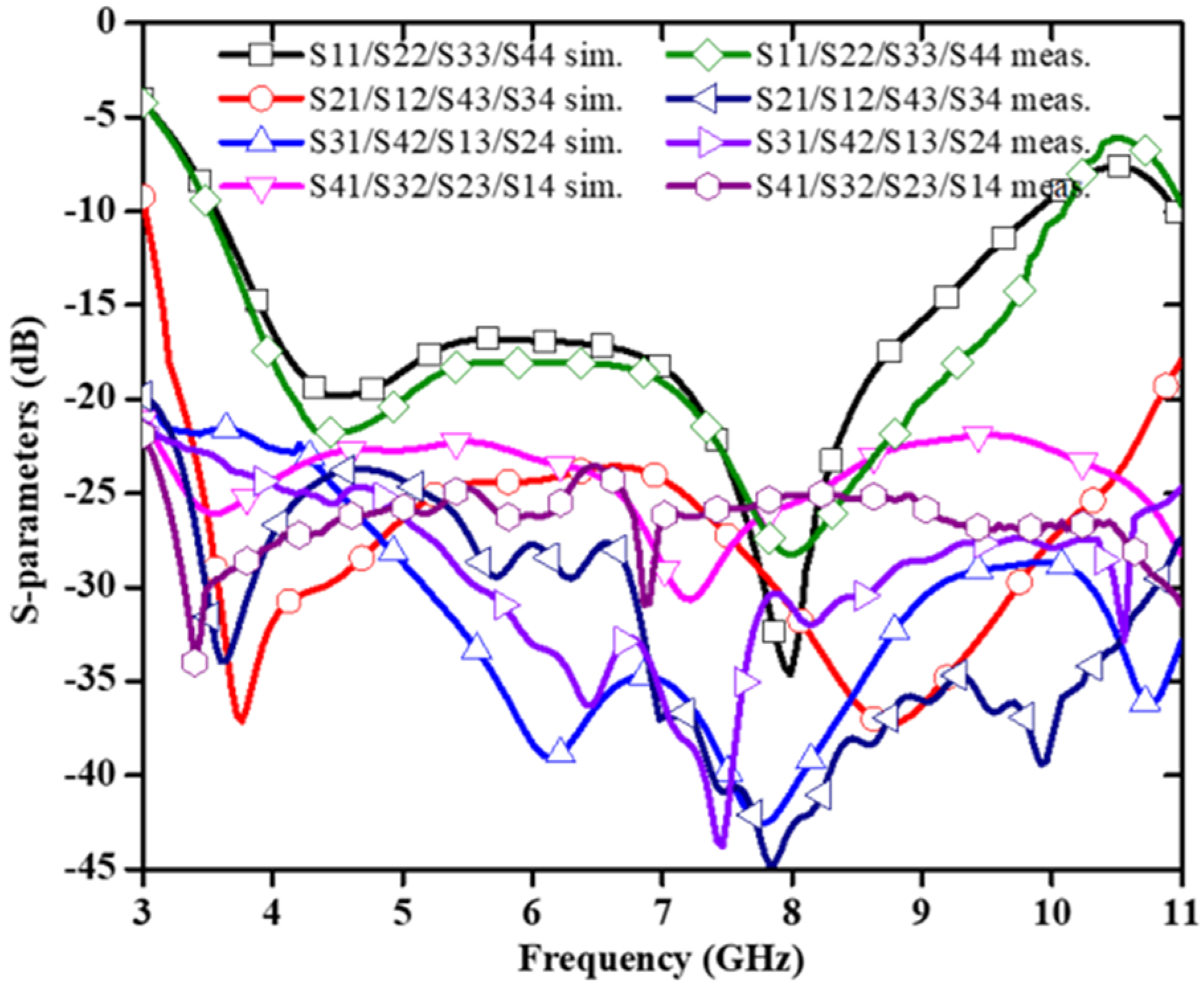
Figure 5. S–parameters of the designed antenna [22].
In [23], a UWB MIMO antenna with defective ground structure (DGS), U-shaped branch step impedance stub, and slotted patch with dimensions of 80 × 35 × 0.508 mm3 is reported and shown in Figure 6. The DGS improves the antenna bandwidth significantly. By adding U-shaped branches, the antenna achieves different resonance characteristics. Step impedance converters produce better impedance matching as compared to standard linear transmission lines. The diagonal arrangement of U-strips is employed to increase the isolation of the antenna. The antenna gain ranges from 3.58 to 5.79 dBi, and from Figure 7 it is found that the relative impedance bandwidth of the design is 131% (2.57–12.2 GHz). The maximum measured value of isolation is −15 dB with an ECC value < 0.005.
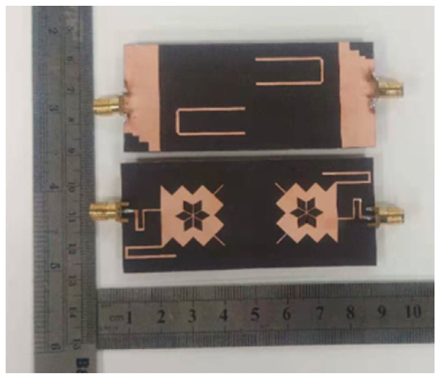
Figure 6. Fabricated prototype of the structure [23].
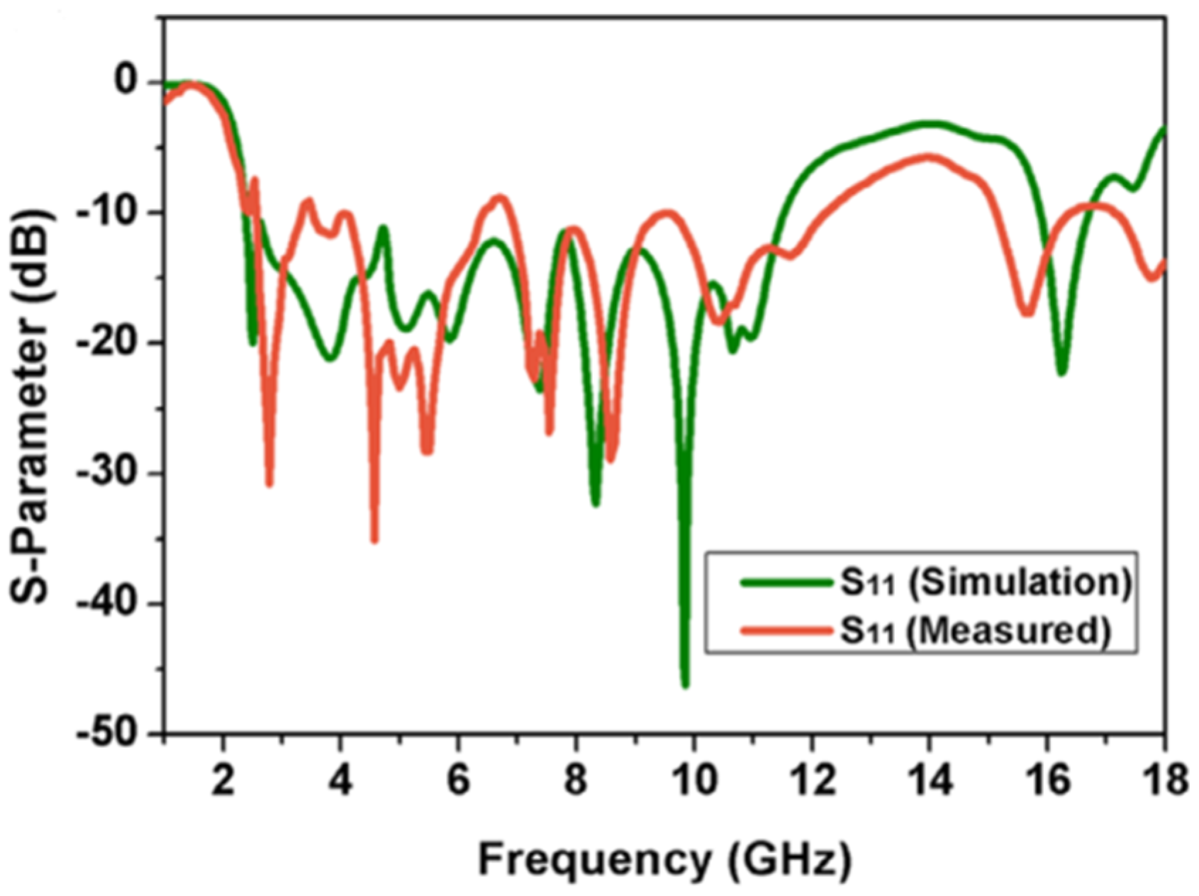
Figure 7. Simulated and measured S–parameters of the antenna [23].
A corner-truncated rhombus-shaped radiating patch is responsible for UWB range [24]. Moreover, to enhance the decoupling effect, a small rectangular stub is connected in the GP and placed between two ports. The MEG is measured using a far-field radiation pattern, which shows a value of −6 dB. A compact wideband MIMO antenna has two identical monopole radiating components engraved on top of the substrate along with a GP including a flag-shaped stub and strips at the bottom [25]. UWB frequency is achieved by adding the slits and slots situated next to the flag-shaped stub. This antenna supports wireless systems such as LTE, WiMAX, WLAN, and HIPERLAN and runs on several standards. In [26], the neutralization line is used between the radiating elements to cancel the field between the neighboring radiating components. The antenna impedance changes as a result of the field cancellation and the coupling between the antennas is decreased. To enhance impedance bandwidth, a UWB MIMO antenna implements two symmetric slot antenna components with quasi F-shaped radiators and L-shaped open-slots [27]. The currents flowing between the closely spaced patches are ejected through a tapered slot carved on the array GP, resulting in a novel antenna with a decoupling structure as suggested in [28]. The idea adopted in this design is to separate coupled currents by passing them through a tapered slot. In [29], the wideband operation is achieved by a central conjoined circular slot. In [30], a UWB MIMO design achieves better isolation without the need of any decoupling techniques taking full use of the monopole asymmetrical structure. In this design, wide bandwidth is achieved by using a radiating patch with a split form. To increase the isolation, two elements on the front side of the MIMO antenna are placed orthogonal to the back-side elements and a circular radiating patch provides good wideband operation [31]. In addition to that, decoupling structures are placed on the top and bottom layers of the substrate to further reduce the mutual coupling between the ports. To decrease mutual coupling, spatial diversity and polarization diversity techniques are applied and a staircase-shaped patch provides UWB frequency range [32]. In [33], four drop-shaped slot antennas are placed perpendicular to one another but in separate layers to limit the transmission of the surface current to the other radiators for improving the isolation. Seven vertical metallic barriers are placed on the front side of the antenna and two L-shaped stubs along with a vertical metallic barrier printed on the back side to strengthen the isolation between the two radiating elements [34]. In addition to that, a circular radiating patch with a small hemisphere on the top of the circle is utilized to achieve wider bandwidth. The introduction of a fence-type decoupling structure at the GP improves the isolation in the working band and the rectangular slot on the radiation patch enhances the resonance characteristics [35]. Moreover, two L-shaped parasitic branches are added on the surface of the dielectric substrate with the goal of improving the mutual coupling at lower frequency (3–3.4 GHz) and the impedance matching performance. In [36], a MIMO antenna is made up of two identical antenna elements that are symmetrically arranged in opposite directions on the same dielectric substrate. High isolation and good impedance matching are accomplished by loading three X-shaped stubs between two disconnected ground planes. In [37], the antenna is made up of four similar patches arranged in an orthogonal pattern. The total size of the antenna is reduced by using a rectangular GP below the radiating patch to produce a monopole design. The use of T- and C-shaped stubs/slots on the radiating patch reduces interfering bands for WiMAX, LTE43, and WLAN and achieve super wideband [38]. Dielectric resonator antennas (DRA) [39][40][41] can also be used to develop a dual-element wide band MIMO antenna system. The wide bandwidth is achieved by merging the two neighboring modes of a wideband A-shaped DRA stimulated by a simple rectangular conformal strip [39]. A mushroom-shaped dielectric resonator activated by a conformal trapezoidal patch is reported in [40] to achieve wideband operation.
4. Dual-Band MIMO Antenna Designs
A dual-band antenna transmits and receives radio signals at two different frequencies. These antennas may use any of the two frequencies separately or both at the same time, depending on their arrangement and applications. Dual-band antennas are widely used with 2.4 GHz and 5 GHz frequency bands. Dual-band allows for quicker speeds and greater versatility. As a result, the dual-band eliminates connection problems and provides more reliability, flexibility and stability. The high gain and omnidirectional Wi-Fi coverage of dual-band antennas [42] make them perfect for a wide range of applications, including vast interior areas, warehouses, buildings, naval installations and many more. Figure 8 shows a design approach for dual band MIMO antennas. The dual-band MIMO antenna designed for WLAN application is made up of closely spaced symmetric MIMO antennas with a 5.3 mm edge-to-edge spacing [43].
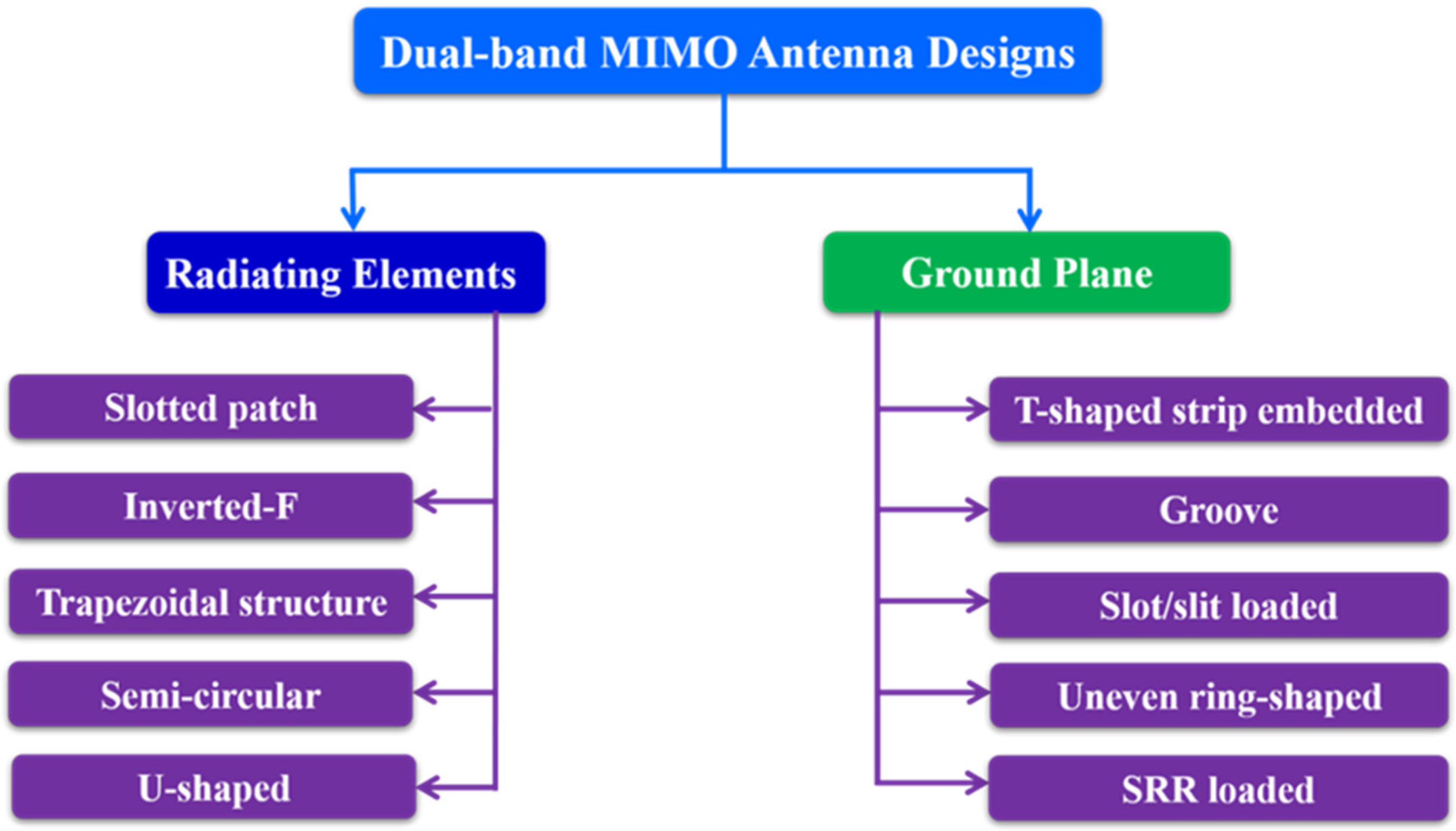
Figure 8. Dual-band MIMO antenna design approaches.
Additionally, a decoupling network is added between the two patches to improve isolation without increasing the footprint. The dual band characteristics are achieved by changing the length of two monopole arms. An elliptical slot and a rectangular parasitic strip are used to establish isolation over the operating dual bands [44]. A dual-band MIMO antenna with two C- shaped patches is employed and a bent T-shaped structure is implanted between the two monopole radiators to provide good isolation [45]. To decrease inter-element coupling, an open slit in the GP is used in a dual-band MIMO antenna design [46].
In [47], back-to-back C-type slot resonators are connected in a radiating patch of a CPW-fed dual-band MIMO antenna using an artificial magnetic conductor as shown in Figure 9. The antenna elements are separated by a gap of 8.3 mm, and the antenna resonates at 3.5 and 5.2 GHz (Figure 10 and Figure 11). Although, there is already a significant amount of isolation at the lower band, a U-shaped slot is introduced in the GP to further boost the isolation at the upper frequency band.
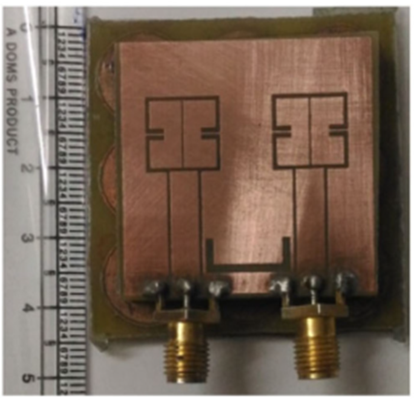
Figure 9. Prototype of CPW-fed MIMO design [47].
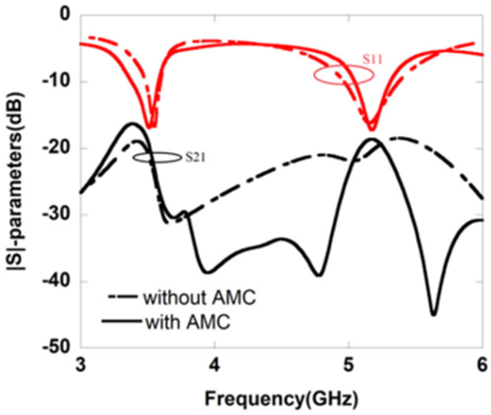
Figure 10. Simulated S–parameters for MIMO antenna [47].
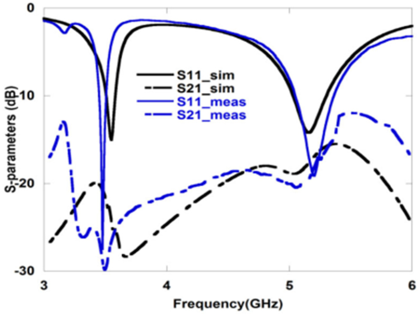
Figure 11. Measured S–parameters for dual-band MIMO antenna [47].
A 2 × 2 dual-band MIMO antenna with size of 46 × 30 × 1.6 mm3 is reported in [48]. A swastika-shaped slot in the rectangular patch makes up the intended dual-band CPW-fed MIMO antenna as shown in Figure 12. Moreover, to increase the isolation between the two radiating components, a T-shaped narrow conducting strip is connected in the GP.
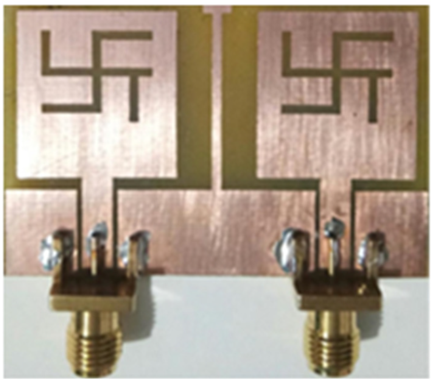
Figure 12. Fabricated two-element dual-band MIMO antenna [48].
It is found that lower and higher frequency bandwidths of the design are 64.96% (1.85–3.63 GHz) and 44.36% (5.07–7.96 GHz), with isolation values ≤−17.21 dB and ≤−22.42 dB, respectively (Figure 13). The observed realized gain varies between 1.14 and 4.12 dBi (lower band) and 1.42 and 4.78 dBi (upper band), with a radiation efficiency > 72% for both frequency bands. This MIMO antenna covers the applications in DCS, LTE2300/2500, Bluetooth, ISM, and WLAN. The radiation patterns at 3.12, 5.29 and 7.18 GHz are evaluated and it is found that the E-plane pattern is dumb-bell shaped while the H-plane is omnidirectional in nature. The T-shaped strip embedded in the ground plane minimizes the electromagnetic coupling between the patches and hence the radiation patterns are least affected.
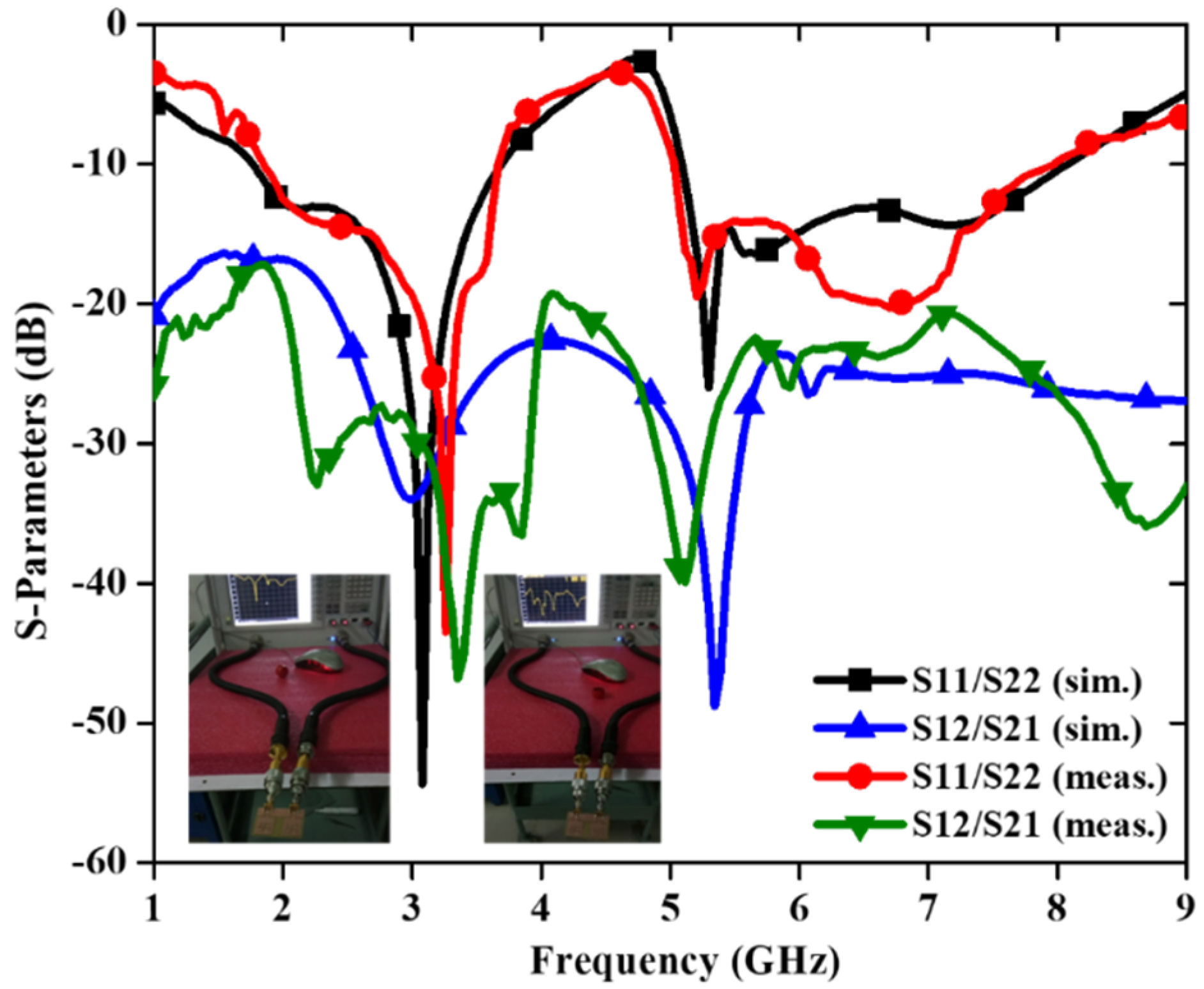
Figure 13. S–parameter of the dual-band MIMO antenna [48].
In [49], a trident-shaped dual-port MIMO antenna with dimensions 62 × 25.6 × 1.524 mm3 is shown in Figure 14.
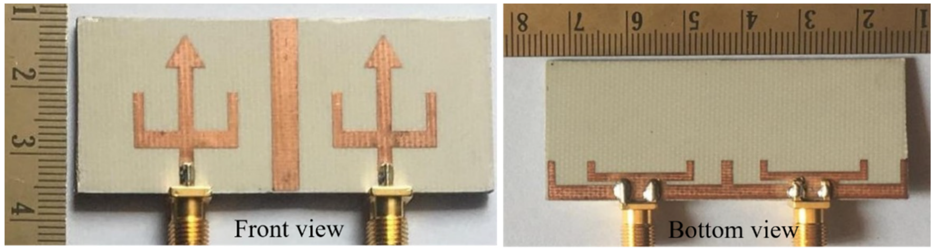
Figure 14. Top and bottom view of fabricated antenna [49].
To obtain the dual-band characteristics, an arrow-shaped strip is placed between the U-shaped patch with two L-shaped slots on the GP. The dual frequency bands cover the frequency range from 2.99 to 3.61 GHz (lower band) and 4.53 to 4.92 GHz (higher band) with isolation ≤ −25 dB and ≤−16 dB, respectively (Figure 15). This MIMO antenna effectively covers the 5G and sub 6G n77/n78/n79 spectrum.
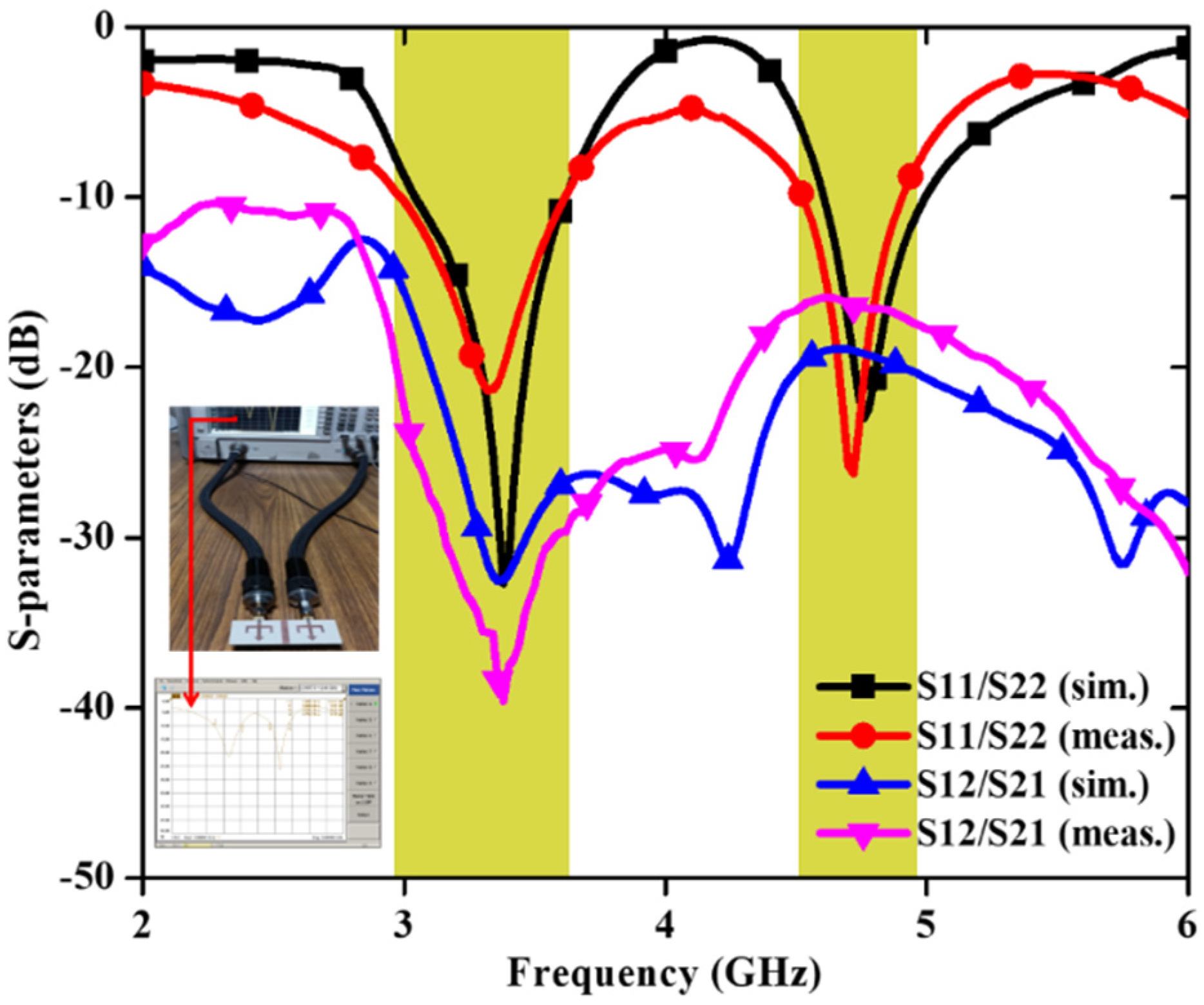
Figure 15. S–parameters of dual-band MIMO antenna [49].
The directional dual-band planar inverted-F antenna (PIFA) element with a small dimension of 31 × 17 mm2 is presented in [50], in which two antenna elements share a common ground with a 3.0 mm edge-to-edge inter-element spacing. Further, it is found that the inverted L-shaped metal arm dimensions are responsible for dual band operation. An inverted T-Shape slot is created on the GP to produce lower and higher frequency bands [51]. A T-shaped strip and a rectangular strip make up the radiating element in [52] and the lower and higher frequency bands are primarily matched by the top and bottom half of the T-shaped strip and the rectangular strip. In [53], six rectangular slots on the trapezoidal structure patch produce two frequency bands and they are achieved by adjusting the length of the rectangular slots. In addition to that, a T-shaped branch contributes to the improvement in isolation of the designed MIMO antenna. In [54], a MIMO antenna with decoupling structure is reported consisting of four L-shaped branches arranged in a counterclockwise direction. Dual band response of the antenna is achieved by varying the length and width of the L-shaped branches. In [55], inverted L-shaped monopole antennas loaded with split-ring resonators (SRRs) are placed in a rotationally symmetric pattern. The inverted L-antenna is responsible for the higher band and by the interaction of the inverted L-antenna and interconnected GP, the lower frequency band is created. The SRR loading makes it easier to build a wide-band antenna mode that can span across lower WLAN, WiFi, and WiMAX application bands. In [56], a meander dipole, a concave parabolic reflector, and a parasitic strip are used to provide good impedance matching in the antenna. The parabolic reflector is used to reduce antenna size and also to improve the lower band directivity. The upper band is created using a metal strip. To accomplish the dual band antenna, in [57], the radiating patch has two asymmetric U-shaped slots printed on the substrate. Improved isolation is achieved by using a composite GP with four metallic strips. In [58], to produce a tiny dual-band WLAN MIMO antenna, lower and higher band dummy elements are employed. The desired frequency bands are achieved by adjusting the width of two branches and the angle between the branches. In [59], to produce a dual band, a rectangle split-ring-resonator (RSRR) slot is placed into the patch. Two arrays of 2 × 1 antenna elements make up an optically transparent MIMO antenna in which a slotted circular ring monopole antenna with a partial GP is used to increase the operation bandwidth and dual band operation [60]. A 2 × 2 MIMO antenna is presented in [61] using a semi-annular patch embedded with a zig-zag conducting strip. It is seen that the higher frequency band is controlled by the zig-zag structure while the lower band is unchanged. Further, the isolation is improved using a fork-shaped feedline. In [62], for a dual-band MIMO antenna, the mushroom type EBG is placed between two antenna elements, providing excellent isolation and reducing mutual coupling. In [63], four simple elliptical-shaped patches are arranged orthogonally around a plus-shaped partial GP. Two opposite slots are introduced into the patch elements to achieve dual band and the plus shape improves the isolation of the designed MIMO antenna. Two symmetrical monopole antenna elements make up the reported MIMO antenna in [64]. By modifying the current distribution on the GP, a DGS and grounded branches are loaded to minimize mutual coupling across the lower band. Between the two antenna elements, there is a T-shaped parasitic element which introduces an inverted path for mutual coupling cancellation, considerably improving the isolation at higher frequency band. As a result, this antenna is capable for 5G dual-band operation. In [65][66], the slots are created on the GP to achieve dual-band MIMO antennas. In [67], for WiMAX/WLAN applications, a compact dual-band MIMO-stacked DRA is designed. The total height of the antenna is 7.0 mm, and the ground area is 50 × 50 mm2. The DGS approach is employed to create strong isolation between antenna ports.
5. Circularly Polarized MIMO Antenna Design Approaches
Circularly polarized (CP) antennas have several significant advantages over linearly polarized antennas. In long-distance communication, circular polarization reduces the losses carried on by polarization mismatch. Additionally, circularly polarized antennas will reduce the spread of multipath propagation delays [68]. CP antennas are rapidly becoming a key component for a wide range of wireless systems, including satellite communications, mobile communications, wireless sensors, radio frequency identification (RFID), wireless power transmission, WLAN [69], wireless personal area networks (WPAN) and global navigation satellite systems (GNSS) [70]. Figure 16 shows some typical design approaches of circularly polarized MIMO antennas. Moreover, some latest designs and methodologies to realize CP MIMO antennas are described in this section.
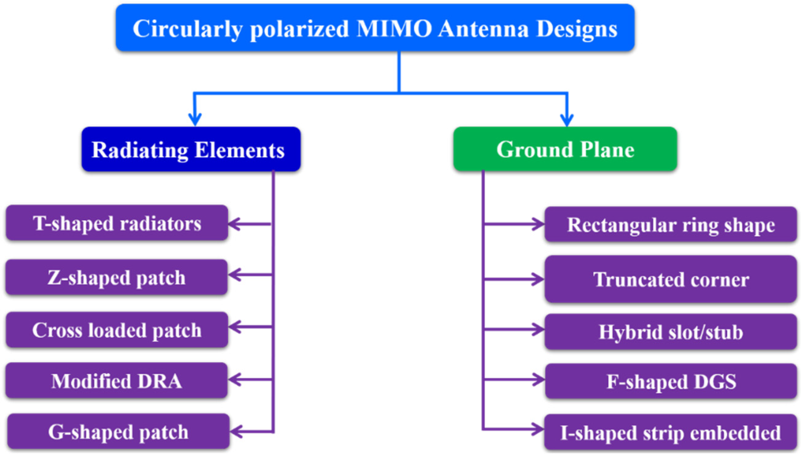
Figure 16. Circularly polarized MIMO antennas design approaches.
Figure 17 shows a small and compact two-port circularly polarized MIMO antenna with dimensions 24 × 24 × 1.6 mm3 [71]. The circularly polarized radiated field of the MIMO antenna is achieved using a unique ground structure implanted with rectangular slots and Z-shaped radiating patches. A meandering U-shaped narrow metallic strip, which provides the good isolation, is placed between the asymmetric Z-shaped radiating components. The impedance bandwidth (3.04–8.11 GHz) of this antenna is 90.94% (Figure 18) and a 3 dB axial ratio bandwidth of 32.10% (4.42–6.11 GHz) is achieved (Figure 19). The ECC and CCL of the reported antenna are found to be 0.004 and 0.32, respectively.
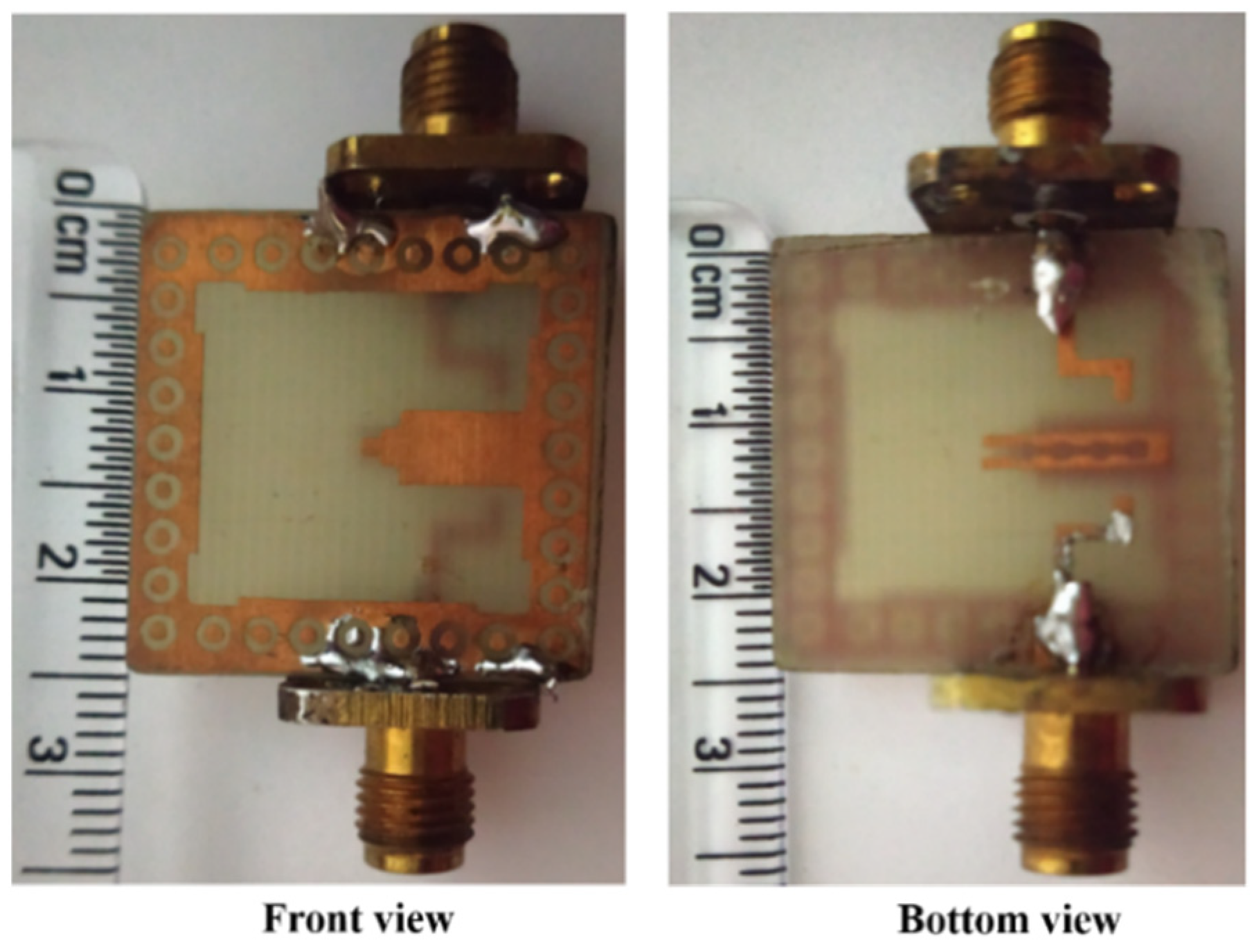
Figure 17. Prototype of circularly polarized MIMO antenna [71].
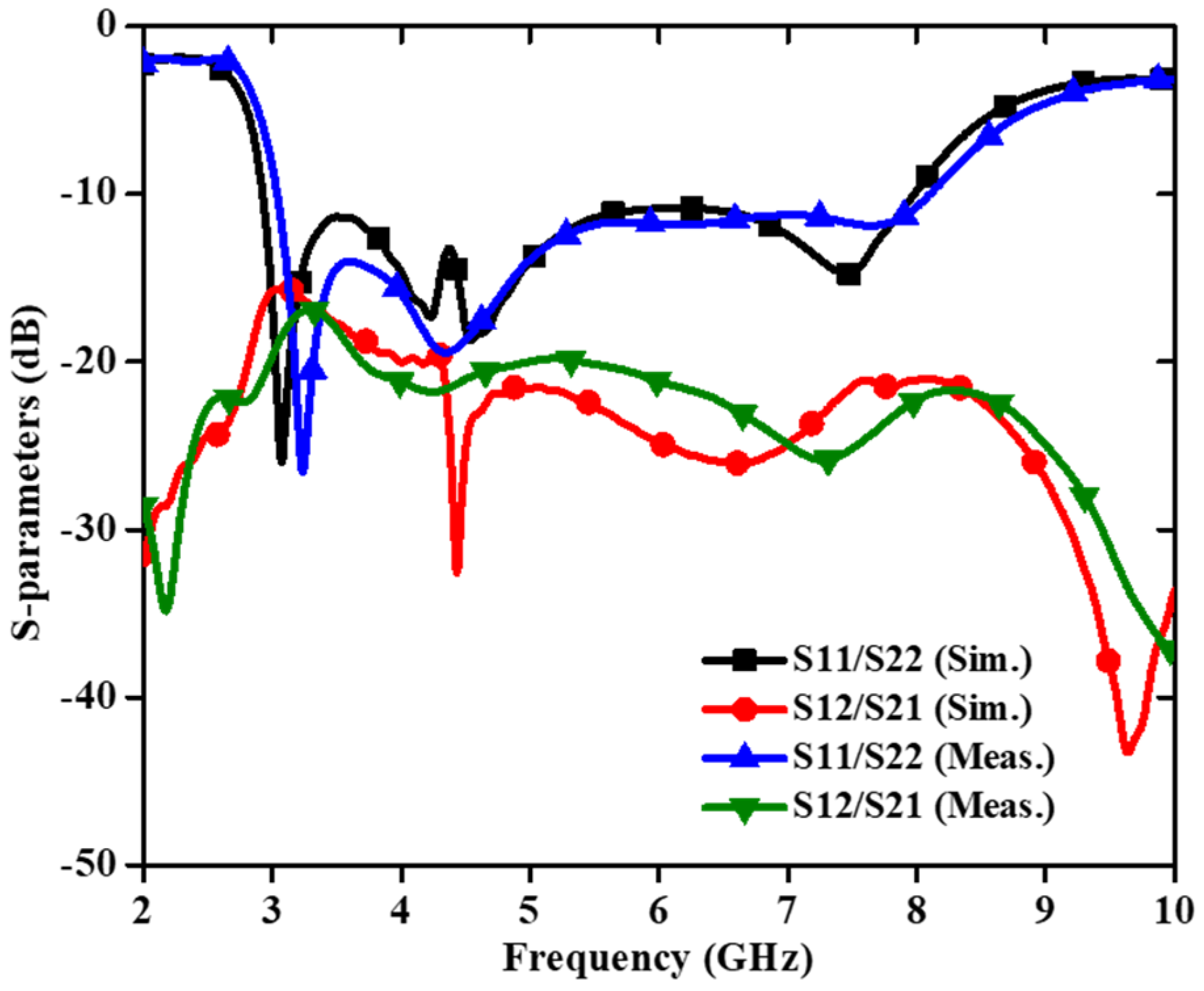
Figure 18. S–parameters of circularly polarized MIMO antenna [71].
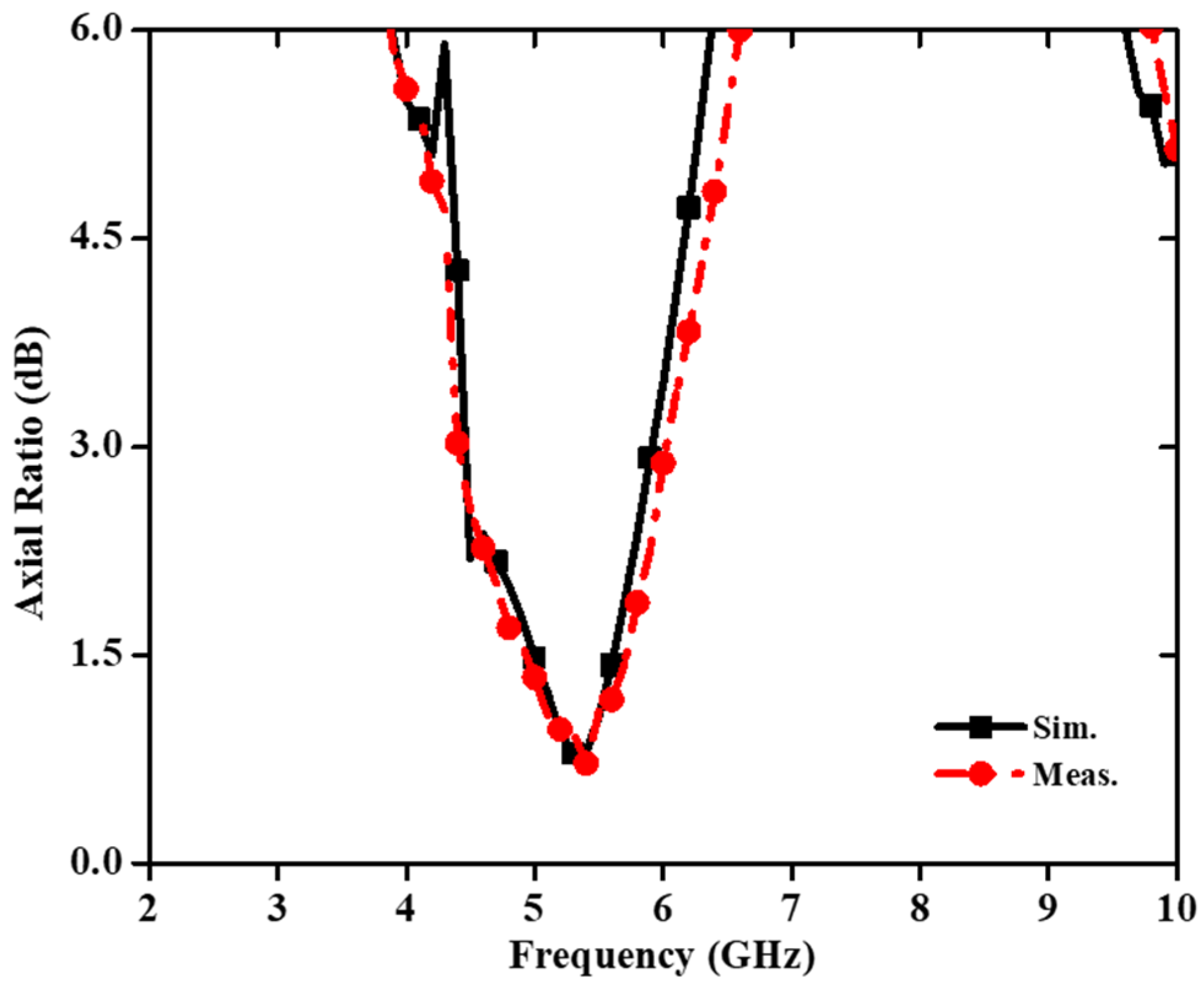
Figure 19. Axial ratio of CP-based MIMO antenna [71].
The circular polarization mechanism can be explained by using the current distribution graph shown in Figure 20. From the figure it is seen that the current density is largely concentrated along the y-axis at time instants t = 0°. The current direction on the radiating patch and on the GP are in opposing directions at t = 90°, but the current flowing on the GP along the x-axis is maximum, and therefore the radiation occurs. With regard to time phase, the present rotation is clockwise, and the radiation is left-hand circular polarization (LHCP) in the +z direction. Furthermore, when the current is rotated in the −z direction, the current rotates anticlockwise, and the radiation received is right-hand circular polarization (RHCP). The radiation pattern is symmetrical, and the RHCP is 18 dB greater than the LHCP in the boresight direction. As a result, there is excellent cross-polarization rejection. In [72], a broadside circularly polarized T-shaped slot antenna and two end-fire CP antennas are combined to create a three-port MIMO antenna system for WLAN application (5.15–5.35 GHz). Figure 21 shows a T-shaped slot antenna with L-shaped feed line to excite the CP wave in the broadside direction. The parallel arrangement of an electric dipole and magnetic dipole with a 90° phase shift is used to create the end-fire CP antenna.

Figure 20. Surface current density at 5.45 GHz [71].
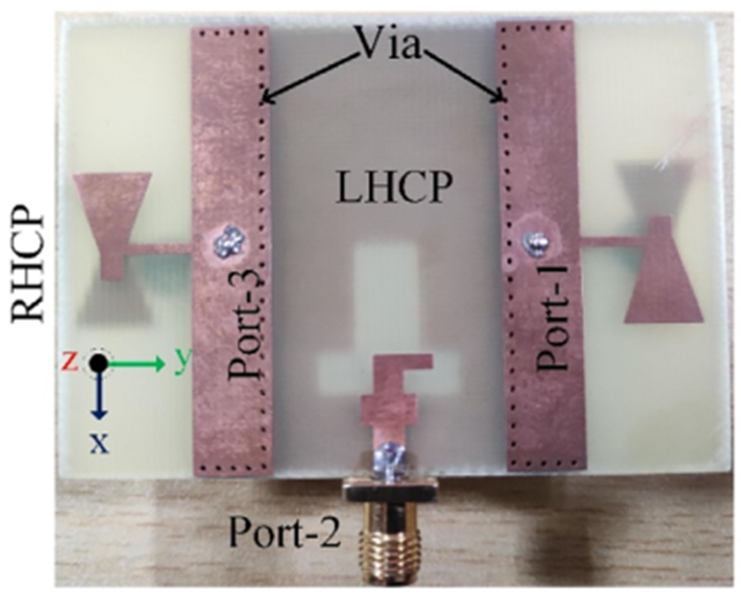
Figure 21. Fabricated circularly polarized MIMO antenna [72].
Figure 22 and Figure 23 show the S-parameters and axial ratio of the designed CP MIMO antenna. Figure 24 shows that a horizontally polarized wave in the +y direction is produced at ωt = 0° by the electric dipole. While the electric field distribution along the open-ended cavity is robust at time phase ωt = 90°, the current distribution on the electric dipole is small. As a result, at ωt = 90°, a vertically polarized wave along the +y-direction is excited by the magnetic dipole. The generation of CP waves along the +y-direction is caused by this 90° phase difference between the electric and magnetic dipoles. Similar effects are also seen for time phases at ωt = 180° and ωt = 270° [72].
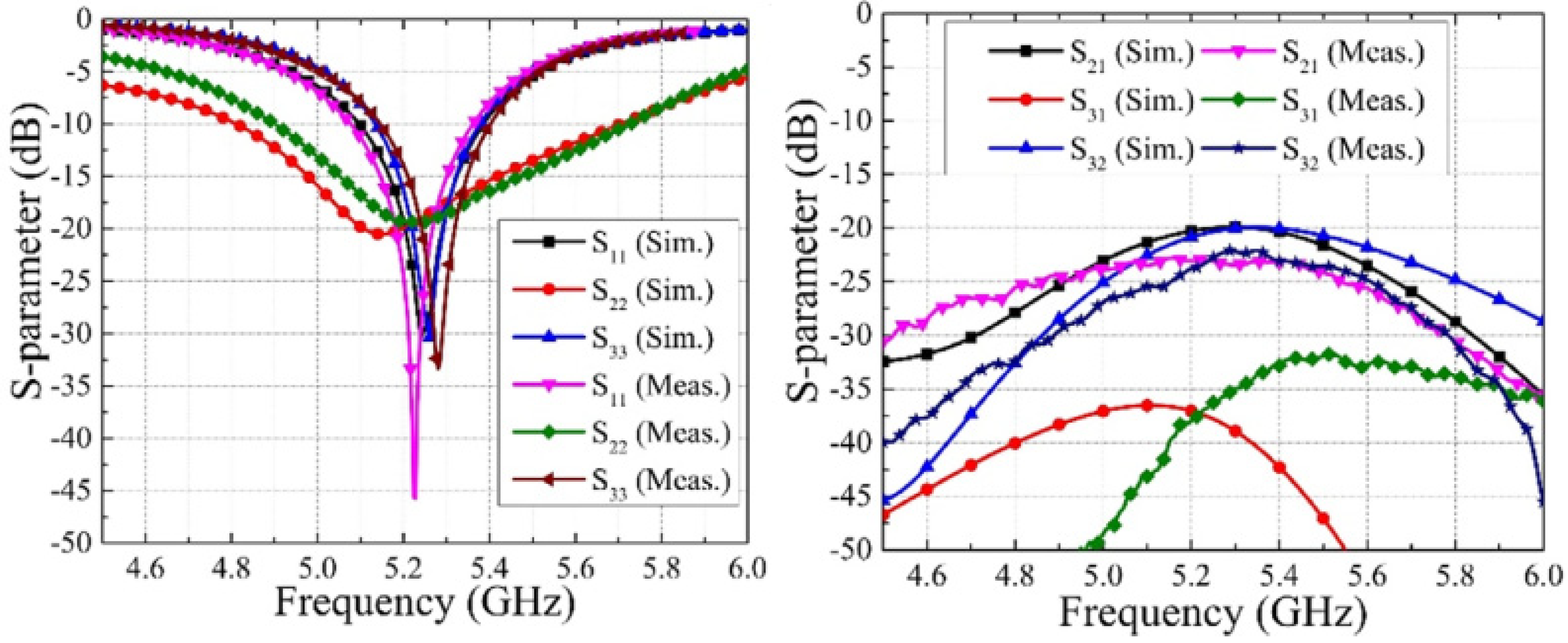
Figure 22. S–parameters of three-port CP MIMO antenna [72].
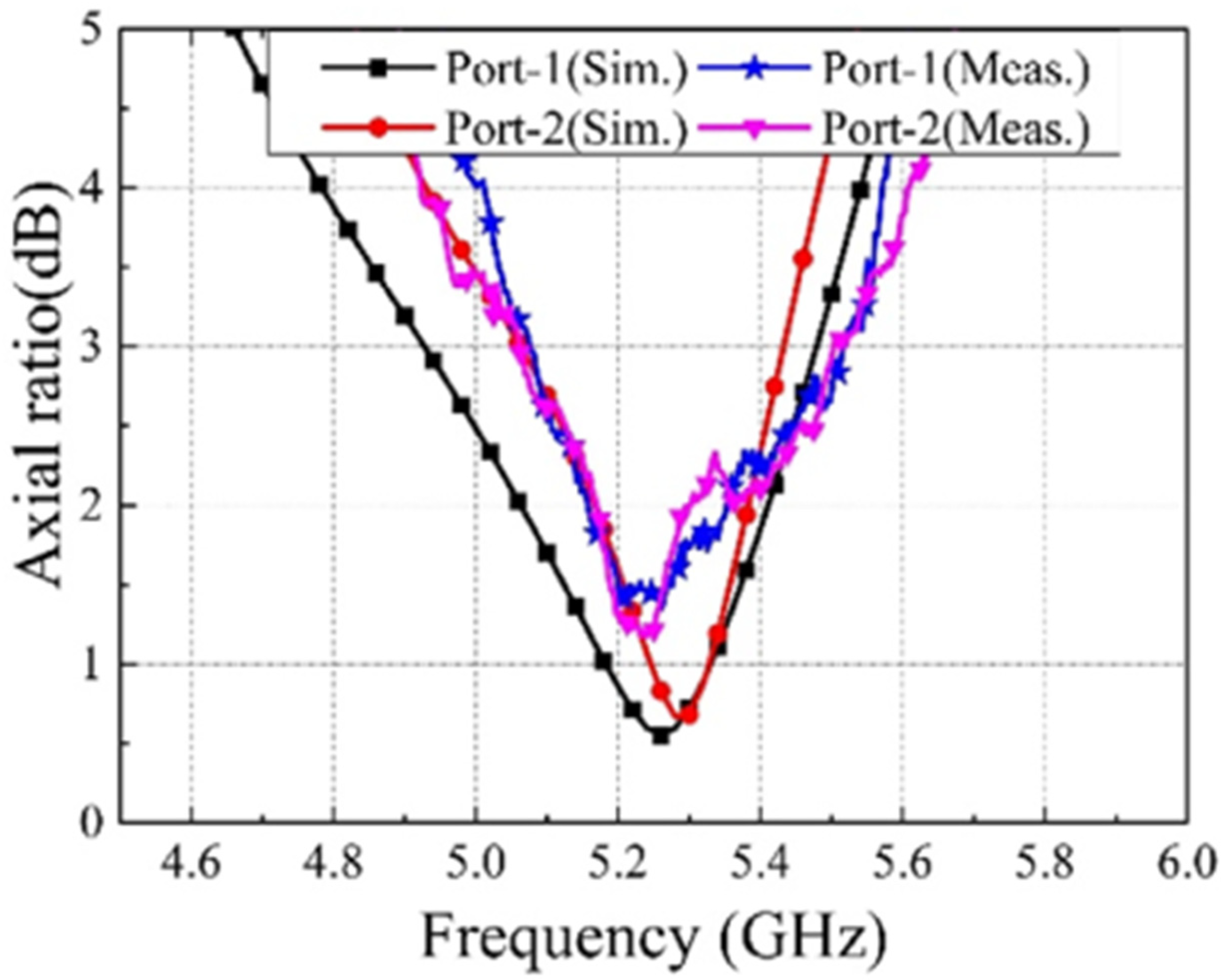
Figure 23. Simulated and measured axial ratio of CP MIMO antenna [72].
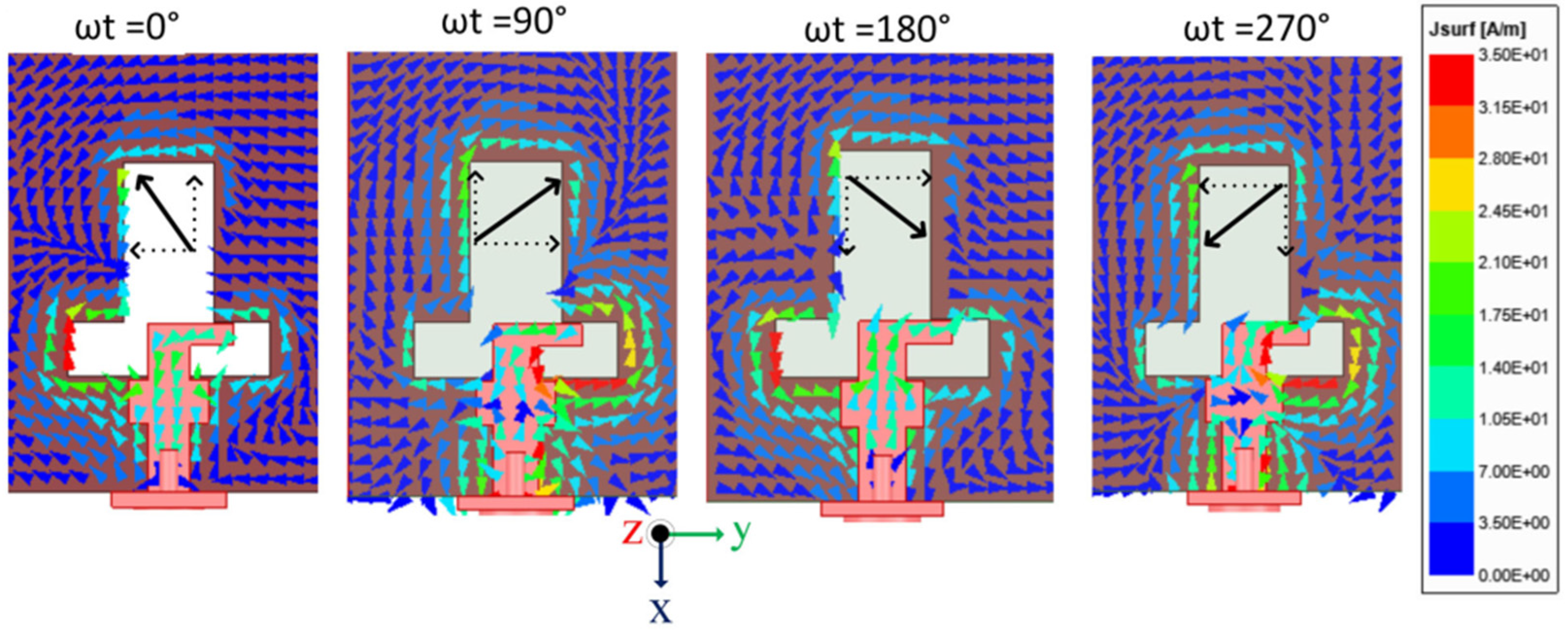
Figure 24. Surface current distribution in 3-port MIMO antenna [72].
6. MIMO Antennas in Indoor Environment
MIMO antennas, when installed within the inhouse region, suffer with the major issue of reduced channel capacity. Some efforts have been made to improve the capacity performance of MIMO systems. Applying frequency-selective (F-S) wallpaper to the walls to block undesired interference with the desired radio communication services is a potential method of resolving indoor situations [73][74]. Considering both SISO and MIMO systems, the features and design of the new F-S wallpaper are reported in [75]. The wallpaper, which is built on symmetric and periodic metallic hexagons, is designed and applied to the ordinary walls in order to block 5 GHz transmissions without obstructing the other radio communication services. The wallpaper is created using the periodic boundary finite-difference time-domain (PB-FDTD) approach based on the unit cell analysis method. In [76], interference levels are decreased using the wallpaper inside a 4 × 4 MIMO system for indoor environments. This MIMO design consists of an array of half-wavelength dipoles for the receiving antenna and a cavity-backed dynamic meta-surface antenna (DMA) for the transmission of the signal. While the transmitter’s location is fixed, the MIMO channels are simulated and the channel capacity is calculated at various receiver locations using the ray tracing approach. Compared to a MIMO system using a sub-aperture phased array for the transmitting antenna, the reported adaptive radiation pattern provided by the DMA can achieve excellent capacity improvement [76].
7. MIMO Characteristics for 6G Technology
Although the 5G mobile communications standard is still in the growing stage of deployment, investigations are in pace for the next generation of wireless technology, 6G wireless systems. In order to overcome the operational difficulties experienced by fifth-generation cellular technology, 6G communication systems are designed to accommodate growing data-hungry applications with boosting connectivity and enhanced network capabilities [77]. The bandwidth and latency of 6G networks will be significantly higher than those of 5G networks due to their ability to operate at higher frequencies. One of the objectives of the 6G internet is to provide communications with a latency of even less than microseconds. It is predicted that 6G would provide extremely dependable low-latency communication with a strong emphasis on internet devices, the application of artificial intelligence in wireless communication and the improvement of mobile broadband [78]. Massive MIMO technology is currently used in 5G communication networks; on the other hand, there will be a need for dozens or even hundreds of antennas and radio links at the base station when 6G technology will be deployed [79]. At the same time, due to the large scale of deployment, there will be high hardware costs, power usage and complicated designs [79]. To fulfill the requirement, upcoming communication systems (6G) are moving towards the higher frequency bands, such as the terahertz (THz) and millimeter-wave bands [80][81]. The internet of nano-things, health monitoring systems, entertainment services, military and ultra-high-speed on-chip communications are some of the significant uses of THz band wireless communication [78][81]. This has encouraged researchers to continuously develop current wireless networks in order to switch over to 6G cellular systems.
8. Conclusions
A comprehensive research on design approaches and applications of MIMO antennas was presented here. Design approaches for ultra-wideband MIMO antennas, dual-band MIMO antennas and circularly polarized MIMO antennas were discussed. The presented research is very useful for researchers working in the field of MIMO antennas. From this research, it is found that the UWB characteristics of MIMO antennas can be achieved by modifying the radiating patches as L-shaped, staircase-shaped, and square-shaped embedded with slits and slots and use of stubs in the patch. Furthermore, creating defects in the GP which includes fence-shaped GPs, different stub loaded designs and tapered slots/slits are some of the methods to improve the antenna bandwidth. Dual-band MIMO antennas can be obtained by incorporating the slots in the radiating patches, U-shaped patches and modification of patches to resonate in the dual/multi frequency band. It is also observed that the uses of SRR-loaded and groove-loaded GP also provide dual- band MIMO antennas. CP-based MIMO antennas are designed by simultaneously optimizing the structure of the patch and the GP. Some basic radiating structures such as cross-loaded patches, G-shaped and Z-shaped patches, and square and circular patches embedded with slots at specific positions and some modified DRAs are used for CP characteristics. The truncated corners and slots itched in the GP with a specific shape, and use of hybrid slots within and at the periphery of the GP are common techniques to improve the CP quality in the MIMO antenna. In addition to that, the isolation techniques in each type of MIMO design are described and presented in tables. In most of the MIMO designs, decoupling parasitic lines are used between the ports to improve the isolation. Moreover, the neutralization line, SRR and EBG structures in the GP as well as between the radiating elements are used for better decoupling. Placing the radiating elements more than the half wavelength of the designed antenna minimizes mutual coupling. Orthogonal orientation of the resonators is also utilized for mutual coupling reduction. The comparison of various antenna parameters including the size, isolation techniques, design methodologies and other characteristics provide an overview of the specific MIMO antenna design. Thus, it is concluded that this research will surely help a lot to enhance the quality and performance of MIMO antenna designs which are demanded by the high data transmission rates of present communication systems, as well as the upcoming 6G technology.
References
- Tao, J.; Feng, Q. Compact ultra-wideband MIMO antenna with half-slot structure. IEEE Antennas Wirel. Propag. Lett. 2016, 16, 792–795.
- Xu, Y.; Dong, Y.; Wen, S.; Wang, H. Vertically polarized quasi-Yagi MIMO antenna for 5G N78 band application. IEEE Access 2021, 9, 7836–7844.
- Sakli, H.; Abdelhamid, C.; Essid, C.; Sakli, N. Metamaterial-based antenna performance enhancement for MIMO system applications. IEEE Access 2021, 9, 38546–38556.
- Garg, P.; Jain, P. Isolation improvement of MIMO antenna using a novel flower shaped metamaterial absorber at 5.5GHz WiMAX band. IEEE Trans. Circuits Syst. 2020, 67, 675–679.
- Wang, Z.; Zhao, L.; Cai, Y.; Zheng, S.; Yin, Y. A meta-surface antenna array decoupling (MAAD) method for mutual coupling reduction in a MIMO antenna system. Sci. Rep. 2018, 8, 3152–3159.
- Xue, C.D.; Zhang, X.Y.; Cao, Y.F.; Hou, Z.; Ding, C.F. MIMO antenna using hybrid electric and magnetic coupling for isolation enhancement. IEEE Trans. Antennas Propag. 2017, 65, 5162–5170.
- Yang, C.; Kim, J.; Kim, H.; Wee, J.; Kim, B.; Jung, C. Quad-band antenna with high isolation MIMO and broadband SCS for broadcasting and telecommunication services. IEEE Antennas Wirel. Propag. Lett. 2010, 9, 584–587.
- Bhattacharya, A.; Roy, B. Investigations on an extremely compact MIMO antenna with enhanced isolation and bandwidth. Microw. Opt. Technol. Lett. 2020, 62, 845–851.
- Larsson, E.G.; Edfors, O.; Tufvesson, F.; Marzetta, T.L. Massive MIMO for next generation wireless systems. IEEE Commun. Mag. 2014, 52, 186–195.
- Pei, T.; Zhu, L.; Wang, J.; Wu, W. A low-profile decoupling structure for mutual coupling suppression in MIMO patch antenna. IEEE Trans. Antennas Propag. 2021, 69, 6145–6153.
- Tiwari, R.N.; Singh, P.; Kumar, P.; Kanaujia, B.K. High isolation 4-port UWB MIMO antenna with novel decoupling structure for high speed and 5G communication. In Proceedings of the 2022 International Conference on Electromagnetics in Advanced Applications (ICEAA), Cape Town, South Africa, 5–9 September 2022; pp. 336–339.
- Ghalib, A.; Sharawi, M.S. TCM analysis of defected ground structures for MIMO antenna designs in mobile terminals. IEEE Access 2017, 5, 19680–19692.
- Pan, B.C.; Cui, T.J. Broadband decoupling network for dual-band microstrip patch antennas. IEEE Trans. Antennas Propag. 2017, 65, 5595–5598.
- Khalid, M.; Iffat Naqvi, S.; Hussain, N.; Rahman, M.; Mirjavadi, S.S.; Khan, M.J.; Amin, Y. 4-port MIMO antenna with defected ground structure for 5G millimeter wave applications. Electronics 2020, 9, 71.
- Niu, Z.; Zhang, H.; Chen, Q.; Zhong, T. Isolation enhancement for 1 × 3 closely spaced E-plane patch antenna array using defect ground structure and metal-vias. IEEE Access 2019, 7, 119375–119383.
- Federal Communications Commission. First Report and Order Revision of Part 15 of the Commission’s Rules Regarding Ultra-Wideband Transmission Systems FCC 02-48; Federal Communications Commission: Washington, DC, USA, 2002.
- Wong, K.L.; Chen, Y.H.; Li, W.Y. Decoupled compact ultra-wideband MIMO antennas covering 3300~6000 MHz for the fifth-generation mobile and 5GHz-WLAN operations in the future smartphone. Microw. Opt. Technol. Lett. 2018, 60, 2345–2351.
- Jehangir, S.S.; Sharawi, M.S. A miniaturized UWB biplanar Yagi-like MIMO antenna system. IEEE Antennas Wirel. Propag. Lett. 2017, 16, 2320–2323.
- Chen, A.; Zhang, J.; Zhao, L.; Yin, Y. A dual-feed MIMO antenna pair with one shared radiator and two isolated ports for fifth generation mobile communication band. Int. J. RF Microw. Comput. Aided Eng. 2017, 27, e21146.
- Zhao, L.; Liu, L.; Cai, Y.M. A MIMO antenna decoupling network composed of inverters and coupled split ring resonators. Prog. Electromagnet. Res. C 2017, 79, 175–183.
- Pandit, S.; Mohan, A.; Ray, P. A compact four-element MIMO antenna for WLAN applications. Microw. Opt. Technol. Lett. 2018, 60, 289–295.
- Tiwari, R.N.; Singh, P.; Kanaujia, B.K.; Srivastava, K. Neutralization technique based two and four port high isolation MIMO antennas for UWB communication. Int. J. Electron. Commun. (AEU) 2019, 110, 152828.
- Tang, X.; Yao, Z.; Li, Y.; Zong, W.; Liu, G.; Shan, F. A high performance UWB MIMO antenna with defected ground structure and U-shape branches. Int. J. RF Microw. Comput. Aided Eng. 2020, 31, e22270.
- Tiwari, R.N.; Singh, P.; Kanaujia, B.K.; Kumar, P. UWB MIMO antenna with decoupling strip for 5G applications. In Proceedings of the 2021 International Applied Computational Electromagnetics Society Symposium (ACES), Hamilton, ON, Canada, 1–5 August 2021; pp. 1–4.
- Katie, M.O.; Jamlos, M.F.; Alqadami, A.S.M.; Jamlos, M.A. Isolation enhancement of compact dual-wideband MIMO antenna using Flag-shaped stub. Microw. Opt. Technol. Lett. 2017, 59, 1028–1032.
- Tiwari, R.N.; Singh, P.; Kanaujia, B.K. A compact UWB MIMO antenna with neutralization line for WLAN/ISM/mobile applications. Int. J. RF Microw. Comput. Aided Eng. 2019, 29, e21907.
- Wang, E.; Wang, W.; Tan, X.; Wu, Y.; Gao, J.; Liu, Y. A UWB slot antenna using defected ground structure for high isolation. Int. J. RF Microw. Comput. Aided Eng. 2020, 30, e22155.
- Tebache, S.; Belouchrani, A.; Ghanem, F.; Mansoul, A. Novel reliable and practical decoupling mechanism for strongly coupled antenna array. IEEE Trans. Antennas Propag. 2019, 67, 5892–5899.
- Barani, I.R.R.; Wong, K.L.; Zhang, Y.X.; Li, W.Y. Low-profile wideband conjoined open-slot antennas fed by grounded coplanar waveguides for 4 × 4 5G MIMO operation. IEEE Trans. Antennas Propag. 2020, 68, 2646–2657.
- Saadh, A.W.M.; Ramaswamy, P.; Ali, T. A CPW fed two and four element antenna with reduced mutual coupling between the antenna elements for wireless applications. Appl. Phys. A 2021, 127, 88.
- Ali, W.A.E.; Ibrahim, A.A. A compact double-sided MIMO antenna with an improved isolation for UWB applications. Int. J. Electron. Commun. (AEU) 2017, 82, 7–13.
- Roshna, T.K.; Deepak, U.; Mohananl, P. Compact UWB MIMO antenna for tridirectional pattern diversity characteristics. IET Microw. Antennas Propag. 2017, 11, 2059–2065.
- Mendez, J.A.T.; Aguilar, H.J.; Merino, A.R.; Toledo, L.A.V.; Villanueva, R.G. Four ports wideband drop-shaped slot antenna for MIMO applications. J. Electromagnet. Waves Applicat. 2020, 34, 1159–1179.
- Ahmed, B.T.; Rodriguez, I.F. Compact high isolation UWB MIMO antennas. Wirel. Netw. 2022, 28, 1977–1999.
- Wang, L.; Du, Z.; Yang, H.; Ma, R.; Zhao, Y.; Cui, X.; Xi, X. Compact UWB MIMO antenna with high isolation using fence-type decoupling structure. IEEE Antennas Wirel. Propag. Lett. 2019, 18, 1641–1645.
- Wang, M.; Nan, J.; Liu, J. High-isolation UWB MIMO antenna with multiple X-shaped stubs loaded between ground planes. Int. J. Antennas Propag. 2021, 2021, 1155471.
- Addepalli, T.; Anitha, V.R. A very compact and closely spaced circular shaped UWB MIMO antenna with improved isolation. Int. J. Electron. Commun. (AEU) 2020, 114, 153016.
- Sharma, M.; Dhasarathan, V.; Patel, S.K.; Nguyen, T.K. An ultra-compact four-port 4 × 4 superwideband MIMO antenna including mitigation of dual notched bands characteristics designed for wireless network applications. Int. J. Electron. Commun. (AEU) 2020, 123, 153332.
- Sharma, A.; Sarkar, A.; Biswas, A.; Akhtar, M.J. A-shaped wideband dielectric resonator antenna for wireless communication systems and its MIMO implementation. Int. J. RF Microw. Comput. Eng. 2018, 28, e21402.
- Sharma, A.; Biswas, A. Wideband multiple-input-multiple-output dielectric resonator antenna. IET Microw. Antenna Propag. 2017, 11, 496–502.
- Gotra, S.; Varshney, G.; Pandey, V.S.; Yaduvanshi, R.S. Super-wideband multi-input-multi-output dielectric resonator antenna. IET Microw. Antennas Propag. 2020, 14, 21–27.
- Tiwari, R.N.; Singh, P.; Kanaujia, B.K.; Kumar, S.; Gupta, S.K. A low profile dual band MIMO antenna for LTE/Bluetooth /Wi-Fi/WLAN applications. J. Electromagnet. Wave Applicat. 2020, 34, 1239–1253.
- Liu, P.; Sun, D.; Wang, P.; Gao, P. Design of a dual-band MIMO antenna with high isolation for WLAN applications. Prog. Electromagnet. Res. Lett. 2018, 74, 23–30.
- Nirmal, P.C.; Nandgaonkar, A.; Nalbalwar, S.; Gupta, R.K. A compact dual-band MIMO antenna with improved isolation for WI-MAX and WLAN applications. Prog. Electromagnet. Res. M 2018, 68, 69–77.
- Liu, Y.; Yang, L.; Liu, Y.; Ren, J.; Wang, J.; Li, X. Dual-band planar MIMO antenna for WLAN application. Microw. Opt. Technol. Lett. 2015, 57, 2257–2262.
- Wu, Y.T.; Chu, Q.X. Dual-band multiple input multiple output antenna with slitted ground. IET Microw. Antennas Propag. 2014, 8, 1007–1013.
- Islam, S.K.N.; Das, S. Dual-band CPW fed MIMO antenna with polarization diversity and improved gain. Int. J. RF Microw. Comput. Aided Eng. 2020, 30, e22128.
- Tiwari, R.N.; Singh, P.; Panday, S.; Anand, R.; Singh, D.K.; Kanaujia, B.K. Swastika shaped slot embedded two port dual frequency band MIMO antenna for wireless applications. Analog Integra. Circuits Signal Process. 2021, 109, 103–113.
- Sharma, P.; Tiwari, R.N.; Singh, P.; Kanaujia, B.K. Dual-band trident shaped MIMO antenna with novel ground plane for 5G applications. Int. J. Electron. Commun. (AEU) 2022, 155, 154364.
- Luo, X.; Yuan, J.; Chen, K. Compact and low profile MIMO antenna for dual-WLAN-band access points. Prog. Electromagnet. Res. Lett. 2017, 67, 97–102.
- Deng, J.Y.; Li, J.Y.; Zhao, L.; Guo, L.X. A dual-band inverted-F MIMO antenna with enhanced isolation for WLAN applications. IEEE Antennas Wirel. Propag. Lett. 2017, 16, 2270–2273.
- Yang, R.; Xi, S.; Cai, Q.; Chen, Z.; Wang, X.; Liu, G. A compact planar dual-band multiple-input and multiple-output antenna with high isolation for 5G and 4G applications. Micromachines 2021, 12, 544.
- Zhao, N.; Tian, W.P. CPW-fed dual-band MIMO antenna with common radiating element. Prog. Electromagnet. Res. Lett. 2016, 62, 71–75.
- Yang, M.; Zhou, J. A compact pattern diversity MIMO antenna with enhanced bandwidth and high-isolation characteristics for WLAN/5G/WiFi applications. Microw. Opt. Technol. Lett. 2020, 62, 2353–2364.
- Sarkar, D.; Srivastava, K.V. Compact four-element SRR-loaded dual-band MIMO antenna for WLAN/WiMAX/WiFi/4G-LTE and 5G applications. Electron. Lett. 2017, 53, 1623–1624.
- Ding, K.; Gao, C.; Qu, D.; Yin, Q. Compact broadband MIMO antenna with parasitic strip. IEEE Antennas Wirel. Propag. Lett. 2017, 16, 2349–2353.
- Tiwari, R.N.; Singh, P.; Kanaujia, B.K.; Kumar, P. Dual band 4-port MIMO antenna for Bluetooth/5G applications. In Proceedings of the 2021 IEEE International Symposium on Antennas and Propagation and USNC-URSI Radio Science Meeting (APS/URSI), Singapore, 4–10 December 2021; pp. 1941–1942.
- Shen, X.; Liu, F.; Zhao, L.; Huang, G.L.; Shi, X.; Huang, Q.; Chen, A. Decoupling of two strongly coupled dual-band antennas with reactively loaded dummy element array. IEEE Access 2019, 7, 154672–154682.
- Kumar, A.; Ansari, A.Q.; Kanaujia, B.K.; Kishor, J. A novel ITI-shaped isolation structure placed between two-port CPW-fed dual-band MIMO antenna for high isolation. Int. J. Electron. Commun. (AEU) 2019, 104, 35–43.
- Desai, A.; Upadhyaya, T.; Palandoken, M.; Gocen, C. Dual band transparent antenna for wireless MIMO system applications. Microw. Opt. Technol. Lett. 2019, 61, 1845–1856.
- Peng, H.; Zhi, R.; Yang, Q.; Cai, J.; Wan, Y.; Liu, G. Design of a MIMO antenna with high gain and enhanced isolation for WLAN applications. Electronics 2021, 10, 1659.
- Maturi, T.; Harikrishna, B. Electronic band-gap integrated low mutual coupling dual band MIMO antenna. Int. J. Electron. 2020, 107, 1166–1176.
- Abdulkawi, W.M.; Malik, W.A.; Rehman, S.U.; Aziz, A.; Sheta, A.F.A.; Alkanhal, M.A. Design of a compact dual-band MIMO antenna system with high-diversity gain performance in both frequency bands. Micromachines 2021, 12, 383.
- Wang, W.; Wu, Y.; Wang, W.; Yang, Y. Isolation enhancement in dual band monopole antenna for 5G applications. IEEE Trans. Circuits Syst. II Exp Briefs 2021, 68, 1867–1871.
- Soltani, S.; Lotfi, P.; Murch, R.D. A dual-band multiport MIMO slot antenna for WLAN applications. IEEE Antennas Wirel. Propag. Lett. 2016, 16, 529–532.
- Nandi, S.; Mohan, A. A compact dual-band MIMO slot antenna for WLAN applications. IEEE Antennas Wirel. Propag. Lett. 2017, 16, 2457–2460.
- Khan, A.A.; Jamaluddin, M.H.; Aqeel, S.; Nasir, J.; Kazim, J.U.R.; Owais, O. Dual-band MIMO dielectric resonator antenna for WiMAX/WLAN applications. IET Microw. Antennas Propag. 2017, 11, 113–120.
- Kumar, A.; Agrawal, T. High performance circularly polarized MIMO antenna with polarization independent metamaterial. Wirel. Pers. Commun. 2021, 16, 3205–3216.
- Malviya, L.; Panigrahi, R.K.; Kartikeyan, M.V. Circularly polarized 2 × 2 MIMO antenna for WLAN applications. Prog. Electromagnet. Res. C 2016, 66, 97–107.
- Hussine, U.U.; Huang, Y.; Song, C. A new circularly polarized antenna for GNSS applications. In Proceedings of the 2017 11th European Conference on Antennas and Propagation (EUCAP), Paris, France, 19–24 March 2017; pp. 1954–1956.
- Tiwari, R.N.; Singh, P.; Kanaujia, B.K.; Kumar, P. Compact circularly polarized MIMO printed antenna with novel ground structure for wideband applications. Int. J. RF Microw. Comput. Aided Eng. 2021, 31, e22737.
- Jaiswal, R.K.; Kumari, K.; Sim, C.Y.D.; Srivastava, K.V. Three-port circularly polarized MIMO antenna for WLAN application with pattern and polarization diversity. Microw Opt. Technol. Lett. 2021, 63, 1927–1934.
- Cho, S.; Hong, I. Reduction of wireless signals in indoor environments by using an active frequency selective wall based on spectrum sensing. Int. J. Commun. Syst. 2017, 30, e3370.
- Yin, W.; Zhang, H.; Zhong, T.; Min, X. A novel compact dual-band frequency selective surface for GSM shielding by utilizing a 2.5-dimensional structure. IEEE Trans. Electromag. Compat. 2018, 60, 2057–2060.
- Rodriguez, J.V.; Gustafsson, M.; Pardo, J.M.M.G.; Llacer, L.J.; Rodriguez, I.R. Frequency-selective wallpaper for indoor interference reduction and MIMO capacity improvement. Symmetry 2020, 12, 695.
- Yoo, I.; Smith, D.R. Dynamic metasurface antennas for higher-order MIMO systems in indoor environments. IEEE Wirel. Communica. Lett. 2020, 9, 1129–1132.
- Alsabah, M.; Naser, M.A.; Mahmmod, B.M.; Abdulhussain, S.H.; Eissa, M.R.; Baidhani, A.A.; Noordin, N.K.; Sait, S.M.; Utaibi, K.A.A.; Hashim, F. 6G Wireless communications networks: A comprehensive survey. IEEE Access 2021, 9, 148191–148243.
- Mahmood, N.H.; Alves, H.; López, O.A.; Shehab, M.; Osorio, D.P.M.; Aho, M.L. Six key features of machine type communication in 6G. In Proceedings of the 2020 2nd 6G Wireless Summit (6G SUMMIT), Levi, Finland, 17–20 March 2020; pp. 1–5.
- Chen, R.; Liu, M.; Hui, Y.; Cheng, N.; Li, J. Reconfigurable intelligent surfaces for 6G IoT wireless positioning: A contemporary survey. IEEE Internet Things J. 2022, 1–13.
- Lee, J.; Kim, H.; Oh, J. Large-aperture metamaterial lens antenna for multi-layer MIMO transmission for 6G. IEEE Access 2022, 10, 20486–20495.
- Dicandia, F.A.; Fonseca, N.J.G.; Bacco, M.; Mugnaini, S.; Genovesi, S. Space-air-ground integrated 6G wireless communication networks: A review of antenna technologies and application scenarios. Sensors 2022, 22, 3136.
More
Information
Subjects:
Engineering, Electrical & Electronic
Contributors
MDPI registered users' name will be linked to their SciProfiles pages. To register with us, please refer to https://encyclopedia.pub/register
:
View Times:
4.7K
Revisions:
2 times
(View History)
Update Date:
27 Oct 2022
Table of Contents


Notice
You are not a member of the advisory board for this topic. If you want to update advisory board member profile, please contact office@encyclopedia.pub.
OK
Confirm
Only members of the Encyclopedia advisory board for this topic are allowed to note entries. Would you like to become an advisory board member of the Encyclopedia?
Yes
No
${ textCharacter }/${ maxCharacter }
Submit
Cancel
Back
Comments
${ item }
|
${ item.createdUser.fullName }
${ item.createdAt }
${ item.vote }
${ item.reply }
Delete
${ reply.createdUser.fullName }
${ reply.createdAt }
${ reply.vote }
Delete
There is no reply to this comment~
${ item.replyTextCharacter }/${ item.replyMaxCharacter }
Submit
Cancel
More
No more~
There is no comment~
${ textCharacter }/${ maxCharacter }
Submit
Cancel
${ selectedItem.replyTextCharacter }/${ selectedItem.replyMaxCharacter }
Submit
Cancel
Confirm
Are you sure to Delete?
Yes
No