
| Version | Summary | Created by | Modification | Content Size | Created at | Operation |
|---|---|---|---|---|---|---|
| 1 | Beatrix Zheng | -- | 3890 | 2022-10-25 01:45:00 |
Video Upload Options
True range multilateration is a method to determine the location of a movable vehicle or stationary point in space using multiple ranges (distances) between the vehicle/point and multiple spatially-separated known locations (often termed 'stations'). True range multilateration is both a mathematical topic and an applied technique used in several fields. A practical application involving a fixed location is the trilateration method of surveying. Applications involving vehicle location are termed navigation when on-board persons/equipment are informed of its location, and are termed surveillance when off-vehicle entities are informed of the vehicle's location. Two slant-ranges from two known locations can be used to locate a third point in a two-dimensional Cartesian space (plane), which is a frequently applied technique (e.g., in surveying). Similarly, two spherical ranges can be used to locate a point on a sphere, which is a fundamental concept of the ancient discipline of celestial navigation — termed the altitude intercept problem. Moreover, if more than the minimum number of ranges are available, it is good practice to utilize those as well. This article addresses the general issue of position determination using multiple ranges. In two-dimensional geometry, it is known that if a point lies on two circles, then the circle centers and the two radii provide sufficient information to narrow the possible locations down to two – one of which is the desired solution and the other is an ambiguous solution. Additional information often narrow the possibilities down to a unique location. In three-dimensional geometry, when it is known that a point lies on the surfaces of three spheres, then the centers of the three spheres along with their radii also provide sufficient information to narrow the possible locations down to no more than two (unless the centers lie on a straight line). True range multilateration can be contrasted to the more frequently encountered (pseudorange) multilateration, which employs range differences to locate a (typically, movable) point. Pseudo range multilateration is almost always implemented by measuring times-of-arrival (TOAs) of energy waves. True range multilateration can also be contrasted to triangulation, which involves the measurement of angles. Multiple, sometimes overlapping and conflicting terms are employed for similar concepts – e.g., multilateration without modification has been used for aviation systems employing both true ranges and pseudo ranges. Moreover, different fields of endeavor may employ different terms. In geometry, trilateration is defined as the process of determining absolute or relative locations of points by measurement of distances, using the geometry of circles, spheres or triangles. In surveying, trilateration is a specific technique. The term true range multilateration is accurate, general and unambiguous. Authors have also used the terms range-range and rho-rho multilateration for this concept.
1. Implementation Issues
Navigation and surveillance systems typically involve vehicles and require that a government entity or other organization deploy multiple stations that employ a form of radio technology (i.e., utilize electromagnetic waves). The advantages and disadvantages of employing true range multilateration for such a system are shown in the following table.
| Advantages | Disadvantages |
|---|---|
| Station locations are flexible; they can be placed centrally or peripherally | Often a user is required to have both a transmitter and a receiver |
| Accuracy degrades slowly with distance from the station cluster | Cooperative system accuracy is sensitive to equipment turn-around error |
| Requires one fewer station than a pseudo range multilateration system | Cannot be used for stealth surveillance |
| Station synchronization is not demanding (based on speed of point of interest, and may be addressed by dead reckoning) | Non-cooperative surveillance involves path losses to the fourth power of distance |
True range multilateration is often contrasted with (pseudo range) multilateration, as both require a form of user ranges to multiple stations. Complexity and cost of user equipage is likely the most important factor in limiting use of true range multilateration for vehicle navigation and surveillance. Some uses are not the original purpose for system deployment – e.g., DME/DME aircraft navigation.
1.2. Obtaining Ranges
For similar ranges and measurement errors, a navigation and surveillance system based on true range multilateration provide service to a significantly larger 2-D area or 3-D volume than systems based on pseudo range multilateration. However, it is often more difficult or costly to measure true ranges than it is to measure pseudo ranges. For distances up to a few miles and fixed locations, true range can be measured manually. This has been done in surveying for several thousand years -- e.g., using ropes and chains.
For longer distances and/or moving vehicles, a radio/radar system is generally needed. This technology was first developed circa 1940 in conjunction with radar. Since then, three methods have been employed:
- Two-way range measurement, one party active – This is the method used by traditional radars (sometimes termed primary radars) to determine the range of a non-cooperative target, and now used by laser rangefinders. Its major limitations are that: (a) the target does not identify itself, and in a multiple target situation, mis-assignment of a return can occur; (b) the return signal is attenuated (relative to the transmitted signal) by the fourth power of the vehicle-station range (thus, for distances of tens of miles or more, stations generally require high-power transmitters and/or large/sensitive antennas); and (c) many systems utilize line-of-sight propagation, which limits their ranges to less than 20 miles when both parties are at similar heights above sea level.
- Two-way range measurement, both parties active – This method was reportedly first used for navigation by the Y-Gerät aircraft guidance system fielded in 1941 by the Luftwaffe. It is now used globally in air traffic control – e.g., secondary radar surveillance and DME/DME navigation. It requires that both parties have both transmitters and receivers, and may require that interference issues be addressed.
- One-way range measurement – The time of flight (TOF) of electromagnetic energy between multiple stations and the vehicle is measured based on transmission by one party and reception by the other. This is the most recently developed method, and was enabled by the development of atomic clocks; it requires that the vehicle (user) and stations having synchronized clocks. It has been successfully demonstrated with Loran-C and GPS.[1][2] However, it is not considered viable for wide use due to the user equipage required (typically, an atomic clock).
In celestial navigation, the user's distance along the earth's surface to the geographic position (GP) on surface (also termed subpoint) that a heavenly body is directly above is measured with a sextant. Knowledge of the GP's latitude and longitude requires accurate knowledge of time, often obtained from a chronometer (whose invention is generally credited to John Harrison in 1761). Sextants were first implemented around 1731; they replaced the backstaff. The aeronautical sextant was introduced in 1922. The major drawback of celestial navigation is availability.
2. Solution Methods
True range multilateration algorithms may be partitioned based on (a) problem space dimension (generally, two or three), (b) problem space geometry (generally, Cartesian or spherical) and (c) presence of redundant measurements (more than the problem space dimension).
2.1. Two Cartesian Dimensions, Two Measured Slant Ranges (Trilateration)
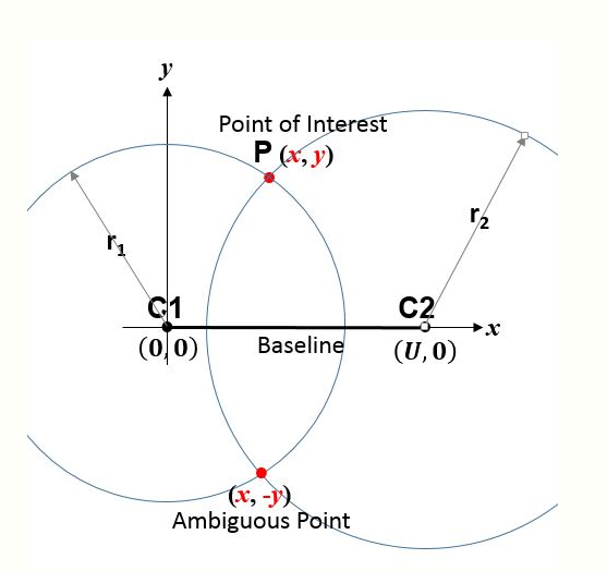
An analytic solution has likely been known for over 1,000 years, and is given in several texts.[3] Moreover, one can easily adapt algorithms for a three dimensional Cartesian space.
The simplest algorithm employs analytic geometry and a station-based coordinate frame. Thus, consider the circle centers (or stations) C1 and C2 in Fig. 1 which have known coordinates (e.g., have already been surveyed) and thus whose separation [math]\displaystyle{ U }[/math] is known. The figure 'page' contains C1 and C2. If a third 'point of interest' P (e.g., a vehicle or another point to be surveyed) is at unknown point [math]\displaystyle{ (x,y) }[/math], then Pythagoras's theorem yields
- [math]\displaystyle{ \begin{align} r_1^2 & = x^2 + y^2 \\[4pt] r_2^2 & = (U-x)^2 + y^2 \end{align} }[/math]
Thus,
-
-
[math]\displaystyle{ \begin{align} x & = \frac { r_1^2 - r_2^2 + U^2 } {2 U} \\[4pt] y & = \pm \sqrt{r_1^2 - x^2} \end{align} }[/math]
()
-
While there are many enhancements, Equation 1 is the most fundamental true range multilateration relationship. Aircraft DME/DME navigation and the trilateration method of surveying are examples of its application. During World War II Oboe and during the Korean War SHORAN used the same principle to guide aircraft based on measured ranges to two ground stations. SHORAN was later used for off-shore oil exploration and for aerial surveying. The Australian Aerodist aerial survey system utilized 2-D Cartesian true range multilateration.[4] This 2-D scenario is sufficiently important that the term trilateration is often applied to all applications involving a known baseline and two range measurements.
The baseline containing the centers of the circles is a line of symmetry. The correct and ambiguous solutions are perpendicular to and equally distant from (on opposite sides of) the baseline. Usually, the ambiguous solution is easily identified. For example, if P is a vehicle, any motion toward or away from the baseline will be opposite that of the ambiguous solution; thus, a crude measurement of vehicle heading is sufficient. A second example: surveyors are well aware of which side of the baseline that P lies. A third example: in applications where P is an aircraft and C1 and C2 are on the ground, the ambiguous solution is usually below ground.
If needed, the interior angles of triangle C1-C2-P can be found using the trigonometric law of cosines. Also, if needed, the coordinates of P can be expressed in a second, better-known coordinate system—e.g., the Universal Transverse Mercator (UTM) system—provided the coordinates of C1 and C2 are known in that second system. Both are often done in surveying when the trilateration method is employed.[5] Once the coordinates of P are established, lines C1-P and C2-P can be used as new baselines, and additional points surveyed. Thus, large areas or distances can be surveyed based on multiple, smaller triangles—termed a traverse.
An implied assumption for the above equation to be true is that [math]\displaystyle{ r_1 }[/math] and [math]\displaystyle{ r_2 }[/math] relate to the same position of P. When P is a vehicle, then typically [math]\displaystyle{ r_1 }[/math] and [math]\displaystyle{ r_2 }[/math] must be measured within a synchronization tolerance that depends on the vehicle speed and the allowable vehicle position error. Alternatively, vehicle motion between range measurements may be accounted for, often by dead reckoning.
A trigonometric solution is also possible (side-side-side case). Also, a solution employing graphics is possible. A graphical solution is sometimes employed during real-time navigation, as an overlay on a map.
2.2. Three Cartesian Dimensions, Three Measured Slant Ranges
There are multiple algorithms that solve the 3-D Cartesian true range multilateration problem directly (i.e., in closed-form) – e.g., Fang.[6] Moreover, one can adopt closed-form algorithms developed for pseudo range multilateration.[3][7] Bancroft's algorithm[8] (adapted) employs vectors, which is an advantage in some situations.
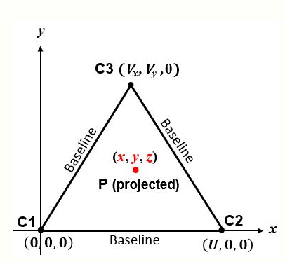
The simplest algorithm corresponds to the sphere centers in Fig. 2. The figure 'page' is the plane containing C1, C2 and C3. If P is a 'point of interest' (e.g., vehicle) at [math]\displaystyle{ (x,y,z) }[/math], then Pythagoras's theorem yields the slant ranges between P and the sphere centers:
- [math]\displaystyle{ \begin{align} r_1^2 & = x^2 + y^2 + z^2 \\[4pt] r_2^2 & = (x-U)^2 + y^2 + z^2 \\[4pt] r_3^2 & = (x-V_x)^2 + (y-V_y)^2 + z^2 \end{align} }[/math]
Thus, letting [math]\displaystyle{ V^2 = V_x^2 + V_y^2 }[/math], the coordinates of P are:
-
-
[math]\displaystyle{ \begin{align} x & = \frac { r_1^2 - r_2^2 + U^2 } {2 U} \\[4pt] y & = \frac { r_1^2 - r_3^2 + V^2 - 2 V_x x } {2 V_y} \\[4pt] z & = \pm \sqrt{r_1^2 - x^2 - y^2} \end{align} }[/math]
()
-
The plane containing the sphere centers is a plane of symmetry. The correct and ambiguous solutions are perpendicular to it and equally distant from it, on opposite sides.
Many applications of 3-D true range multilateration involve short ranges—e.g., precision manufacturing.[9] Integrating range measurement from three or more radars (e.g., FAA's ERAM) is a 3-D aircraft surveillance application. 3-D true range multilateration has been used on an experimental basis with GPS satellites for aircraft navigation.[2] The requirement that an aircraft be equipped with an atomic clock precludes its general use. However, GPS receiver clock aiding is an area of active research, including aiding over a network. Thus, conclusions may change.[10] 3-D true range multilateration was evaluated by the International Civil Aviation Organization as an aircraft landing system, but another technique was found to be more efficient.[11] Accurately measuring the altitude of aircraft during approach and landing requires many ground stations along the flight path.
2.3. Two Spherical Dimensions, Two or More Measured Spherical Ranges
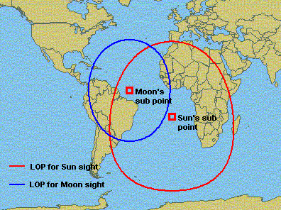
This is a classic celestial (or astronomical) navigation problem, termed the altitude intercept problem (Fig. 3). It's the spherical geometry equivalent of the trilateration method of surveying (although the distances involved are generally much larger). A solution at sea (not necessarily involving the sun and moon) was made possible by the marine chronometer (introduced in 1761) and the discovery of the 'line of position' (LOP) in 1837. The solution method now most taught at universities (e.g., U.S. Naval Academy) employs spherical trigonometry to solve an oblique spherical triangle based on sextant measurements of the 'altitude' of two heavenly bodies.[12][13] This problem can also be addressed using vector analysis.[14] Historically, graphical techniques – e.g., the intercept method – were employed. These can accommodate more than two measured 'altitudes'. Owing to the difficulty of making measurements at sea, 3 to 5 'altitudes' are often recommended.
As the earth is better modeled as an ellipsoid of revolution than a sphere, iterative techniques may be used in modern implementations.[15] In high-altitude aircraft and missiles, a celestial navigation subsystem is often integrated with an inertial navigation subsystem to perform automated navigation—e.g., U.S. Air Force SR-71 Blackbird and B-2 Spirit.
While intended as a 'spherical' pseudo range multilateration system, Loran-C has also been used as a 'spherical' true range multilateration system by well-equipped users (e.g., Canadian Hydrographic Service).[1] This enabled the coverage area of a Loran-C station triad to be extended significantly (e.g., doubled or tripled) and the minimum number of available transmitters to be reduced from three to two. In modern aviation, slant ranges rather than spherical ranges are more often measured; however, when aircraft altitude is known, slant ranges are readily converted to spherical ranges.[3]
2.4. Redundant Range Measurements
When there are more range measurements available than there are problem dimensions, either from the same C1 and C2 (or C1, C2 and C3) stations, or from additional stations, at least these benefits accrue:
- 'Bad' measurements can be identified and rejected
- Ambiguous solutions can be identified automatically (i.e., without human involvement) -- requires an additional station
- Errors in 'good' measurements can be averaged, reducing their effect.
The iterative Gauss–Newton algorithm for solving non-linear least squares (NLLS) problems is generally preferred when there are more 'good' measurements than the minimum necessary. An important advantage of the Gauss–Newton method over many closed-form algorithms is that it treats range errors linearly, which is often their nature, thereby reducing the effect of range errors by averaging.[7] The Gauss–Newton method may also be used with the minimum number of measured ranges. Since it is iterative, the Gauss–Newton method requires an initial solution estimate.
In 3-D Cartesian space, a fourth sphere eliminates the ambiguous solution that occurs with three ranges, provided its center is not co-planar with the first three. In 2-D Cartesian or spherical space, a third circle eliminates the ambiguous solution that occurs with two ranges, provided its center is not co-linear with the first two.
2.5. One-Time Application Versus Repetitive Application
This article largely describes 'one-time' application of the true range multilateration technique, which is the most basic use of the technique. With reference to Fig. 1, the characteristic of 'one-time' situations is that point P and at least one of C1 and C2 change from one application of the true range multilateration technique to the next. This is appropriate for surveying, celestial navigation using manual sightings, and some aircraft DME/DME navigation.
However, in other situations, the true range multilateration technique is applied repetitively (essentially continuously). In those situations, C1 and C2 (and perhaps Cn, n = 3,4,...) remain constant and P is the same vehicle. Example applications (and selected intervals between measurements) are: multiple radar aircraft surveillance (5 and 12 seconds, depending upon radar coverage range), aerial surveying, Loran-C navigation with a high-accuracy user clock (roughly 0.1 seconds), and some aircraft DME/DME navigation (roughly 0.1 seconds). Generally, implementations for repetitive use: (a) employ a 'tracker' algorithm[16] (in addition to the multilateration solution algorithm), which enables measurements collected at different times to be compared and averaged in some manner; and (b) utilize an iterative solution algorithm, as they (b1) admit varying numbers of measurements (including redundant measurements) and (b2) inherently have an initial guess each time the solution algorithm is invoked.
2.6. Hybrid Multilateration Systems
Hybrid multilateration systems – those that are neither true range nor pseudo range systems – are also possible. For example, in Fig. 1, if the circle centers are shifted to the left so that C1 is at [math]\displaystyle{ x_1^\prime = - \tfrac{1}{2} U, y_1^\prime = 0 }[/math] and C2 is at [math]\displaystyle{ x_2^\prime = \tfrac{1}{2} U, y_2^\prime = 0 }[/math] then the point of interest P is at
- [math]\displaystyle{ \begin{align} x^\prime & = \frac { (r_1^\prime + r_2^\prime)(r_1^\prime - r_2^\prime) } {2 U} \\[4pt] y^\prime & = \pm \frac { \sqrt{ (r_1^\prime + r_2^\prime)^2 - U^2 } \sqrt{ U^2 - (r_1^\prime - r_2^\prime)^2 } } {2 U} \end{align} }[/math]
This form of the solution explicitly depends on the sum and difference of [math]\displaystyle{ r_1^\prime }[/math] and [math]\displaystyle{ r_2^\prime }[/math] and does not require 'chaining' from the [math]\displaystyle{ x^\prime }[/math]-solution to the [math]\displaystyle{ y^\prime }[/math]-solution. It could be implemented as a true range multilateration system by measuring [math]\displaystyle{ r_1^\prime }[/math] and [math]\displaystyle{ r_2^\prime }[/math].
However, it could also be implemented as a hybrid multilateration system by measuring [math]\displaystyle{ r_1^\prime + r_2^\prime }[/math] and [math]\displaystyle{ r_1^\prime - r_2^\prime }[/math] using different equipment – e.g., for surveillance by a multistatic radar with one transmitter and two receivers (rather than two monostatic radars). While eliminating one transmitter is a benefit, there is a countervailing 'cost': the synchronization tolerance for the two stations becomes dependent on the propagation speed (typically, the speed of light) rather that the speed of point P, in order to accurately measure both [math]\displaystyle{ r_1^\prime \pm r_2^\prime }[/math].
While not implemented operationally, hybrid multilateration systems have been investigated for aircraft surveillance near airports and as a GPS navigation backup system for aviation.[17]
3. Preliminary and Final Computations
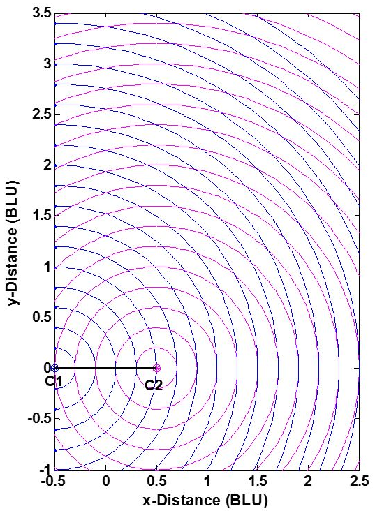
The position accuracy of a true range multilateration system—e.g., accuracy of the [math]\displaystyle{ (x,y) }[/math] coordinates of point P in Fig. 1 -- depends upon two factors: (1) the range measurement accuracy, and (2) the geometric relationship of P to the system's stations C1 and C2. This can be understood from Fig. 4. The two stations are shown as dots, and BLU denotes baseline units. (The measurement pattern is symmetric about both the baseline and the perpendicular bisector of the baseline, and is truncated in the figure.) As is commonly done, individual range measurement errors are taken to be independent of range, statistically independent and identically distributed. This reasonable assumption separates the effects of user-station geometry and range measurement errors on the error in the calculated [math]\displaystyle{ (x,y) }[/math] coordinates of P. Here, the measurement geometry is simply the angle at which two circles cross—or equivalently, the angle between lines P-C1 and P-C2. When point P- is not on a circle, the error in its position is approximately proportional to the area bounded by the nearest two blue and nearest two magenta circles.
Without redundant measurements, a true range multilateration system can be no more accurate than the range measurements, but can be significantly less accurate if the measurement geometry is not chosen properly. Accordingly, some applications place restrictions on the location of point P. For a 2-D Cartesian (trilateration) situation, these restrictions take one of two equivalent forms:
- The allowable interior angle at P between lines P-C1 and P-C2: The ideal is a right angle, which occurs at distances from the baseline of one-half or less of the baseline length; maximum allowable deviations from the ideal 90 degrees may be specified.
- The horizontal dilution of precision (HDOP), which multiplies the range error in determining the position error: For two dimensions, the ideal (minimum) HDOP is the square root of 2 ([math]\displaystyle{ \sqrt{2} \approx 1.414 }[/math]), which occurs when the angle between P-C1 and P-C2 is 90 degrees; a maximum allowable HDOP value may be specified. (Here, equal HDOPs are simply the locus of points in Fig. 4 having the same crossing angle.)
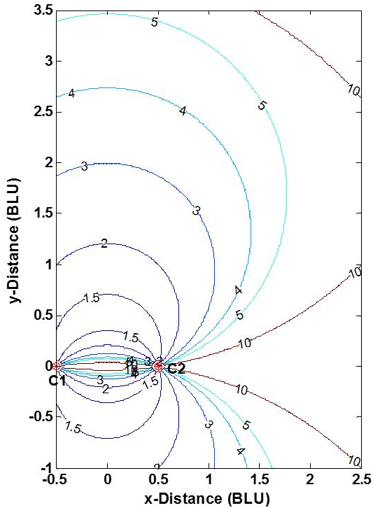
Planning a true range multilateration navigation or surveillance system often involves a dilution of precision (DOP) analysis to inform decisions on the number and location of the stations and the system's service area (two dimensions) or service volume (three dimensions).[18][19] Fig. 5 shows horizontal DOPs (HDOPs) for a 2-D, two-station true range multilateration system. HDOP is infinite along the baseline and its extensions, as only one of the two dimensions is actually measured. A user of such a system should be roughly broadside of the baseline and within an application-dependent range band. For example, for DME/DME navigation fixes by aircraft, the maximum HDOP permitted by the U.S. FAA is twice the minimum possible value, or 2.828,[20] which limits the maximum usage range (which occurs along the baseline bisector) to 1.866 times the baseline length. (The plane containing two DME ground stations and an aircraft in not strictly horizontal, but usually is nearly so.) Similarly, surveyors select point P in Fig. 1 so that C1-C2-P roughly form an equilateral triangle (where HDOP = 1.633).
Errors in trilateration surveys are discussed in several documents.[21][22] Generally, emphasis is placed on the effects of range measurement errors, rather than on the effects of algorithm numerical errors.
4. Example Applications
- Land surveying using the trilateration method
- Aerial surveying
- Maritime archeology surveying[23]
- DME/DME RNAV aircraft navigation[20][24]
- Multiple radar integration (e.g., FAA ERAM)[25]
- Celestial navigation using the altitude intercept method
- Intercept method—Graphical solution to the altitude intercept problem
- Calibrating laser interferometers[9]
- SHORAN, Oboe, Gee-H—Aircraft guidance systems developed for 'blind' bombing
- JTIDS (Joint Tactical Information Distribution System) -- U.S./NATO system that (among other capabilities) locates participants in a network using inter-participant ranges
- USAF SR-71 Blackbird aircraft—Employs astro-inertial navigation
- USAF B-2 Spirit aircraft—Employs astro-inertial navigation
References
- "Rho-Rho Loran-C Combined with Satellite Navigation for Offshore Surveys". S.T. Grant, International Hydrographic Review, undated
- Impact of Rubidium Clock Aiding on GPS Augmented Vehicular Navigation, Zhaonian Zhang; University of Calgary; December, 1997. https://www.ucalgary.ca/engo_webdocs/GL/97.20112.ZNZhang.pdf
- Earth-Referenced Aircraft Navigation and Surveillance Analysis, Michael Geyer, U.S. DOT John A. Volpe National Transportation Systems Center, June 2016. https://rosap.ntl.bts.gov/view/dot/12301
- Adastra Aerial Surveys retrieved Jan. 22, 2019. http://www.adastra.adastron.com/equip/aerodist.htm
- "The Nature of Geographic Information: Trilateration", Pennsylvania State Univ., 2018. https://www.e-education.psu.edu/natureofgeoinfo/c5_p12.html
- "Trilateration and extension to global positioning system navigation", B.T. Fang, Journal of Guidance, Control, and Dynamics, vol. 9 (1986), pp 715–717.
- "Closed-form Algorithms in Mobile Positioning: Myths and Misconceptions", Niilo Sirola, Proceedings of the 7th Workshop on Positioning, Navigation and Communication 2010 (WPNC'10), March 11, 2010.
- "An Algebraic Solution of the GPS Equations", Stephen Bancroft, IEEE Transactions on Aerospace and Electronic Systems, Volume: AES-21, Issue: 7 (Jan. 1985), pp 56–59. http://ieeexplore.ieee.org/search/searchresult.jsp?searchWithin=p_Authors:.QT.Bancroft,%20S..QT.&searchWithin=p_Author_Ids:37296953500&newsearch=true
- LaserTracer – A New Type of Self Tracking Laser Interferometer, Carl-Thomas Schneider, IWAA2004, CERN, Geneva, October 2004 http://www.slac.stanford.edu/econf/C04100411/papers/054.PDF
- "How a Chip-Scale Atomic Clock Can Help Mitigate Broadband Interference"; Fang-Cheng Chan, Mathieu Joerger, Samer Khanafseh, Boris Pervan, and Ondrej Jakubov; GPS World -- Innovations; May 2014. https://www.gpsworld.com/innovation-reducing-the-jitters/
- "Microwave Landing System"; Thomas E. Evans; IEEE Aerospace and Electronic Systems Magazine; Vol. 1, Issue 5; May 1986. https://ieeexplore.ieee.org/document/5005109
- Spherical Trigonometry, Isaac Todhunter, MacMillan; 5th edition, 1886. https://www.gutenberg.org/files/19770/19770-pdf.pdf
- A treatise on spherical trigonometry, and its application to geodesy and astronomy, with numerous examples, John Casey, Dublin, Hodges, Figgis & Co., 1889.
- "Vector-based geodesy", Chris Veness. 2016. https://www.movable-type.co.uk/scripts/latlong-vectors.html
- "STELLA (System To Estimate Latitude and Longitude Astronomically)", George Kaplan, John Bangert, Nancy Oliversen; U.S. Naval Observatory, 1999.
- Tracking and Data Fusion: A Handbook of Algorithms; Y. Bar-Shalom, P.K. Willett, X. Tian; 2011
- "Alternative Position, Navigation, and Timing: The Need for Robust Radionavigation"; M.J. Narins, L.V. Eldredge, P. Enge, S.C. Lo, M.J. Harrison, and R. Kenagy; Chapter in Global Navigation Satellite SystemsJoint Workshop of the National Academy of Engineering and the Chinese Academy of Engineering (2012). https://www.nap.edu/read/13292/chapter/13
- "Dilution of Precision", Richard Langeley, GPS World, May 1999, pp 52–59. http://www2.unb.ca/gge/Resources/gpsworld.may99.pdf
- Accuracy Limitations of Range-Range (Spherical) Multilateration Systems, Harry B. Lee, Massachusetts Institute of Technology, Lincoln Laboratory, Technical Note 1973-43, Oct. 11, 1973. https://rosap.ntl.bts.gov/view/dot/12134
- "DME/DME for Alternate Position, Navigation, and Timing (APNT)", Robert W. Lilley and Robert Erikson, Federal Aviation Administration, White Paper, July 23, 2012. https://www.faa.gov/about/office_org/headquarters_offices/ato/service_units/techops/navservices/gnss/library/documents/APNT/media/20120723APNT_DMEWhitePaper_dc.pdf
- Statistical Methods in Surveying by Trilateration; William Navidi, William S Murphy, Jr and Willy Hereman; December 20, 1999. https://pdfs.semanticscholar.org/fdfb/dfc1de2568b71e5bdfc4348a819b72597206.pdf
- Comparison of the Accuracy of Triangulation, Trilateration and Triangulation-Trilateration; K.L. Provoro; Novosibirsk Institnte of Engineers of Geodesy; 1960. https://apps.dtic.mil/dtic/tr/fulltext/u2/650359.pdf
- "Trilateration in Maritime Archeology", YouTube, U.S. National Oceanic and Atmospheric Administration, 2006. https://www.youtube.com/watch?v=iis6-Kz9YFA
- "DME/DME Accuracy", Michael Tran, Proceedings of the 2008 National Technical Meeting of The Institute of Navigation, San Diego, CA, January 2008, pp. 443–451.
- "Radar Basics", Christian Wolff, undated http://www.radartutorial.eu/02.basics/rp52.en.html


