Your browser does not fully support modern features. Please upgrade for a smoother experience.
Submitted Successfully!
 +1 credit
Thank you for your contribution! You can also upload a video entry or images related to this topic.
For video creation, please contact our Academic Video Service.
| Version | Summary | Created by | Modification | Content Size | Created at | Operation |
|---|---|---|---|---|---|---|
| 1 | Liyang Liu | -- | 4546 | 2022-10-20 11:01:43 | | | |
| 2 | Amina Yu | + 3 word(s) | 4549 | 2022-10-21 03:17:12 | | |
Video Upload Options
We provide professional Academic Video Service to translate complex research into visually appealing presentations. Would you like to try it?
Cite
If you have any further questions, please contact Encyclopedia Editorial Office.
Liu, L.; Tian, Y.; Abdussalam, A.; Gilani, M.R.H.S.; Zhang, W.; Xu, G. Hard Carbons as Anodes in Sodium-Ion Batteries. Encyclopedia. Available online: https://encyclopedia.pub/entry/30462 (accessed on 02 August 2026).
Liu L, Tian Y, Abdussalam A, Gilani MRHS, Zhang W, Xu G. Hard Carbons as Anodes in Sodium-Ion Batteries. Encyclopedia. Available at: https://encyclopedia.pub/entry/30462. Accessed August 02, 2026.
Liu, Liyang, Ye Tian, Abubakar Abdussalam, Muhammad Rehan Hasan Shah Gilani, Wei Zhang, Guobao Xu. "Hard Carbons as Anodes in Sodium-Ion Batteries" Encyclopedia, https://encyclopedia.pub/entry/30462 (accessed August 02, 2026).
Liu, L., Tian, Y., Abdussalam, A., Gilani, M.R.H.S., Zhang, W., & Xu, G. (2022, October 20). Hard Carbons as Anodes in Sodium-Ion Batteries. In Encyclopedia. https://encyclopedia.pub/entry/30462
Liu, Liyang, et al. "Hard Carbons as Anodes in Sodium-Ion Batteries." Encyclopedia. Web. 20 October, 2022.
Copy Citation
Sodium-ion batteries (SIBs) are regarded as promising alternatives to lithium-ion batteries (LIBs) in the field of energy, especially in large-scale energy storage systems. Tremendous effort has been put into the electrode research of SIBs, and hard carbon (HC) stands out among the anode materials due to its advantages in cost, resource, industrial processes, and safety. However, different from the application of graphite in LIBs, HC, as a disordered carbon material, leaves more to be completely comprehended about its sodium storage mechanism, and there is still plenty of room for improvement in its capacity, rate performance and cycling performance.
hard carbon
Sodium-ion batteries
electrolyte
anode
carbon materials
modification
electrochemical performance
1. Carbon Based Anode Materials
1.1. Graphite
Graphite is the most widely applied material in lithium-ion batteries (LIBs) and serves as the host structure of the anode delivering a high capacity of 372 mAh g−1 [1]. However, it is severely limited when used in sodium-ion batteries (SIBs) containing carbonate electrolyte, as the capacity drops to less than 50 mAh g−1. Nevertheless, graphite has high stability and is fully commercialized, it is dedicated to be applied in SIBs as an anode by overcoming the inability of the Sodium-ion to form graphite intercalation compounds (Na-GICs) and restricts the insertion of Na due to thermodynamic instability [2]. The main effective solutions include: (i) introducing oxygen-containing functional groups through redox reaction [3] or morphology design [4] to increase the layer spacing for stable Na-GICs formation; and (ii) using a Sodium-ion solvent co-intercalation storage mechanism combined with an ether-based electrolyte [5][6].
The above two schemes have contributed to the mechanism of Sodium-ion storage between graphite layers, which have also assisted when investigating and comprehending sodium storage behavior in hard carbon (HC) materials [7][8]. However, the solvent requirement is relatively high and the reversible specific capacity is far less than that of HC, which makes the large-scale industrialization of graphite anodes difficult. For example, Wang’s group [4] synthesized an expanded graphite as a superior anode, which showed a high reversible capacity of 284 mAh g−1 at a current density of 20 mA g−1 and retained 73.92% of its capacity after 2000 cycles.
1.2. Soft Carbon
With respect to amorphous carbon, including HC and soft carbon, the main difference lies in the graphitization or non-graphitization under high pyrolytic temperature. The degree of graphitization increases with a rise of pyrolytic temperature, forming a turbostratic disordered structure. Compared with HC, soft carbon tends to form large, stacked graphene layers in the stacking direction and base plane. HC, however, is characterized by a small area of graphite microcrystalline and a larger area of randomly oriented nanoscale pores even at elevated temperatures above 2800 °C.
Owing to the advantages of low-cost, adjustable layer spacing and its considerable electronic conductivity, soft carbon also shows good performance as an anode material for SIBs. Defect-rich soft carbon porous nanosheets [9], when used as an anode material, can reach a capacity of 232 mAh g−1 and a superior rate capability of 103 mAh g−1 at 1000 mA g−1. Li and co-workers [10] prepared soft carbon with pyrolytic anthracite as a precursor and achieved a good rate and cycling performance with a reversible capacity of 222 mAh g−1. Practically, soft carbon suffers from low energy density in a full battery assembling since high operating voltage can reduce the working potential.
1.3. Hard Carbon
HC, also called non-graphitizing carbon, is mainly composed of short-range ordered regions of curved graphene sheets in small areas and a wealth of nanopores formed from the microcrystalline areas. The precise structure, size of the graphite microcrystalline zone, number of carbon layers, and the nanopores, are all affected by the carbonization temperature. As early as 2000, Dahn [11] first reported on the application of HC as an anode, using glucose as a carbon source to prepare pyrolytic HC, which provided a high reversible capacity of over 300 mAh g−1. Since then, HC as an anode has attracted tremendous attention, and different HC materials prepared by various kinds of precursors have been reported successively.
The properties of HC anodes have witnessed rapid improvements in recent years. For instance, Yang [12] prepared an N-doped HC with a soybean residue and assembled it with a Na3V2(PO4)3 cathode to show a high full-cell energy density of 146.1 Wh kg−1. Guo’s group [13] utilized chitin derived N-doped amorphous carbon nanofibers as an anode coordinating a Prussian blue cathode to deliver a high reversible capacity of 120 mAh g−1 and over 90% retention rate after 200 cycles. Although HC materials originate from low-cost and abundant resources and show excellent capacity property, HC suffers from relatively poor cycling stability and rate capability; and plenty of strategies are dedicated to reducing these disadvantages, which will be described later in the present contribution.
2. Hard Carbon Materials
2.1. Synthetic Raw Material
It is considered that thermosetting raw materials with a strong crosslinking structure are promising precursors to generate HC materials via pyrolysis. The following materials have been used for the synthesis of HC.
-
Carbohydrate or other organic polymers; for example, sucrose [14][15], cellulose [16][17], and lignin [18] have been used as precursors for the fabrication of HC anodes. In particular, Hu [17] prepared nanofibers with a short-range ordered graphite lattice and porous structures using cellulose as a raw material at the low pyrolysis temperature of 1000 °C. It exhibited a high reversible capacity of 340 mAh g−1.
-
Biomass source; such as peel [19][20][21], chitin [13], cotton [22], algae [23] and many others have also been used in the mass production of HC. The selection of a biomass source precursor plays an important part in the preparation of electrode materials with desired electrochemical properties [24]. According to a study reported by Xu and coauthors, an HC with a large layer spacing was fabricated based on a one-step pyrolysis of grapefruit peel in an inert atmosphere. The as-prepared HC anode has a reversible capacity of 430.5 mAh g−1 at a current density of 30 mA g−1 and remarkable cycling stability [20]. The produced HC showed a honeycomb-like structure and expanded cavities, which facilitated the diffusion of the electrolyte into the bulk of the material and shortened the distance of Sodium-ion insertion. These properties are beneficial to improve the rate capability and reversible capacity.
-
Resin carbon; for example, phenolic resin [25], and polyacrylonitrile [26] are another group of HC precursors. New progress in the research of Zhong’s group has revealed that HC can originate from a polyacrylonitrile doped polar molecule (Melamine). After spinning, they carbonized it to form HC nanofibers, which show a high gravimetric capacity, high-power capability, and long-term cycling stability of 200 mAh g−1 at 1 A g−1 current density after 1200 cycles [27].
2.2. Structure of HC
Thermosetting precursors can undergo solid phase carbonization during pyrolysis. Other elements in the precursor are separated from the structure in the form of gases, and the organic molecules in the interior are fully crosslinked and hard to rearrange, making it difficult to achieve graphitization. However, the carbonaceous materials generated by thermoplastic precursors during carbonization will be affected by the residuals, such as hydrogen and oxygen, and the basic structural units of the thermoplastic precursors will rearrange to form parallel structures that are amenable to graphitization [28], as shown in Figure 1. In the case of carbohydrates, all the H and O evaporate as water, leaving a highly crosslinked network of carbons to form HC. On the contrary, in the pyrolysis process of polyvinyl chloride (PVC), H and Cl will be released in the form of hydrochloric acid gas, and the remaining hydrogen will lead to the formation of hydrocarbons, which remain at a relatively high density to benefit the graphitization and eventually form soft carbon.
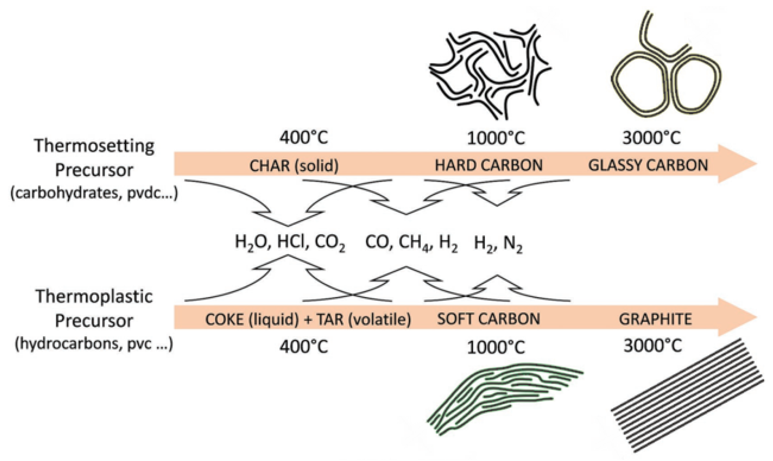
Figure 1. Schematic representation of the carbonization process during the pyrolysis of thermosetting and thermoplastic organic precursors [28].
X-ray diffraction (XRD) is utilized to investigate the crystal structures of carbon materials as shown in Figure 2a. All three carbon materials caused a distinct current signal at about 2θ = 25°, and the main XRD peak of graphite is 26.5°, which corresponds to the characteristic peak of the graphite (002) crystal face. The (002) peak of soft carbon deviates to a lower angle and is wider than that of graphite, indicating that the soft carbon forms a crystal area. Its crystallinity is not as good as graphite and the layer spacing is relatively large. Similarly, the (002) peak of HC is obviously lower in angle and larger in width, because the strong crosslinking interaction prevents the carbon layer from slipping during the pyrolysis process and generates graphite sheets with a higher degree of crystallinity. By comparing the diffraction peak (004) of the three materials, the weakening of peak intensity means a decrease of the crystallization degree. From the observation of the in-plane diffraction peak, such as the (100) peak, the angle and width of the (100) peak of soft carbon and HC are similar, which proves the similar internal turbostratic disordered structure, and the main difference between the two is the stacking degree in the c-axis direction. Compared with the (100) peak of graphite, the in-plane diffraction of amorphous carbon is weaker, indicating that more defects and bending structures may be generated in the amorphous carbon. Besides, HC and soft carbon obviously lose the peaks of (101) and (012) of in-plane diffraction, which further confirms the reduction in crystal size and disorder of the internal structure [29].
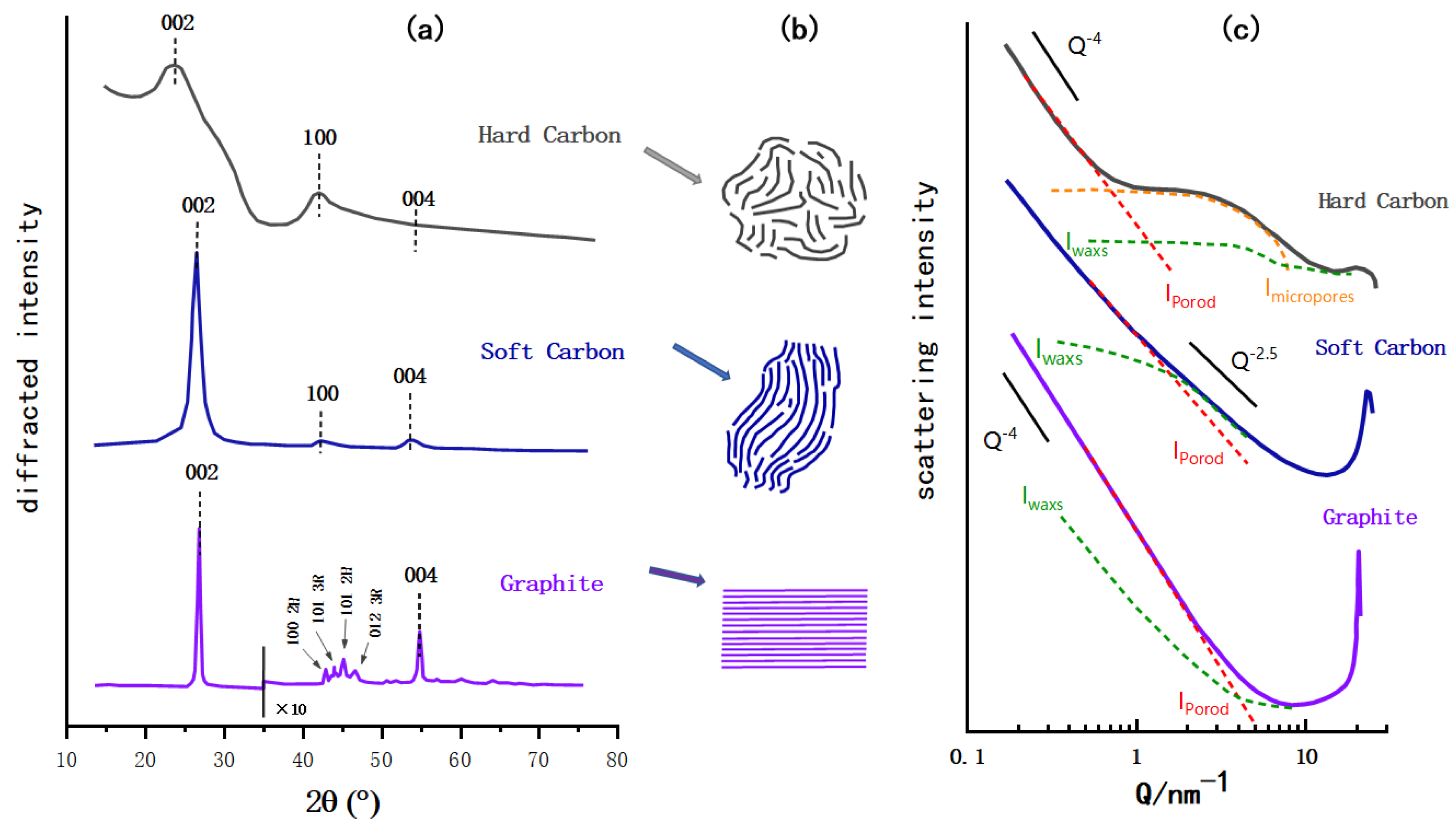
Figure 2. Schematic diagram of HC, soft carbon, and graphite. (a) XRD contrast diagram (modified according to the reference [29], the sharpness of the image after graphite 2θ = 35° as amplified ten times). (b) Schematic diagram of the microstructure of three carbon materials. (c) SAXs contrast diagram (modified according to the reference [30]; the Iwaxs, Iporod and Imicropores are the parameters of the structure and model established in reference).
In Figure 2c, the HC was prepared at 1050 °C by the argon pyrolysis method with dehydrated sucrose as the carbon source, the soft carbon was calcined with a petroleum coke based carbon source, and the graphite was a typical synthetic graphite [30]. The small angle X-ray scattering (SAXs) patterns of the three are compared in the same schematic diagram. Under the low scattering vector, the graphite pattern is an inclined straight line, indicating that it basically has no microporous structure, and the straight line of soft carbon is slightly curved, indicating the roughness of its surface that may have a disordered structure and some micropores. In contrast, HC exhibits its characteristic pattern of a plateau in the range Q = 1~10 nm−1 behind the slanted line of the low scattering vector, which indicates the presence of a microporous structure [31].
Figure 2b shows a simple schematic diagram of the microstructure of HC, soft carbon, and graphite. As noted in the preceded sections, the structure of the amorphous carbon is quite different from that of graphite; the crystallinity, surface defects, number of micropores and graphite layer spacing vary to some extent. In addition to having the same turbostratic disordered structure as soft carbon, HC has a certain degree of crystallization, a greater degree of internal disorder, and more microporous structures. As shown in Figure 3, in terms of crystal parameters, La and Lc (the average width and thickness of crystals stacked along axis-a and axis-c) of HC and soft carbon are relatively close. The rise of pyrolysis temperature increased the La and Lc of soft carbon obviously; therefore, increasing its crystallinity and gradually turning it susceptible to graphitization. However, the change of La and Lc in HC is relatively gentle [32], proving that it is more difficult to undergo graphitization.
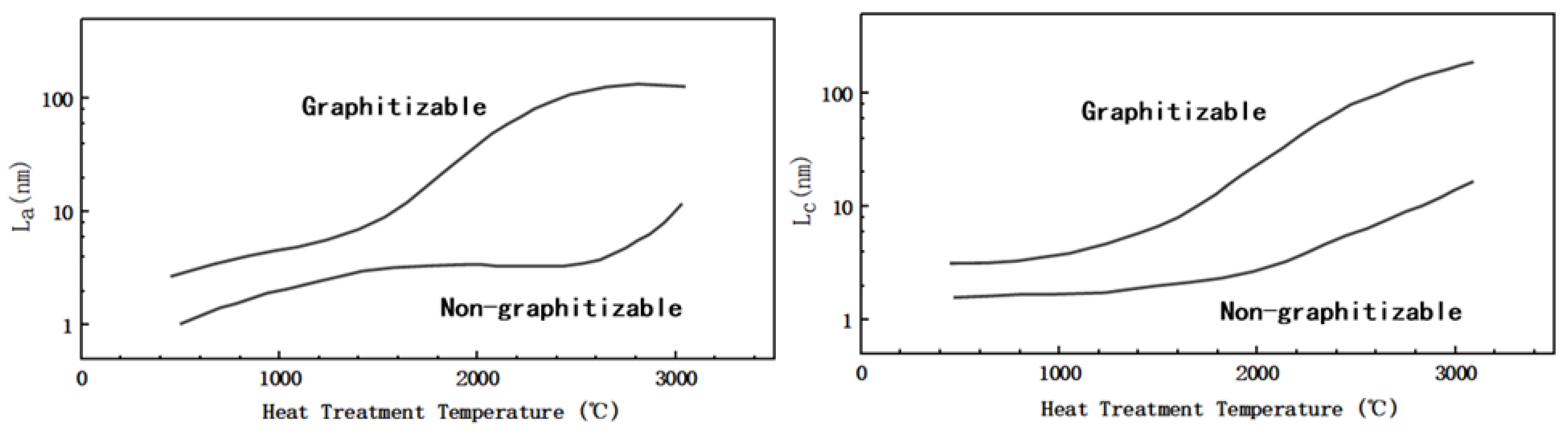
Figure 3. Schematic diagram of La and Lc of soft and HC changing with treatment temperature (modified by reference [32]).
2.3. Sodium Storage Mechanism of HC
The research on the sodium storage mechanism of HC materials provides SIBs with several advantages in the development of a large-scale energy storage system with long-standing stability. According to previous reports, the way Sodium-ions are stored in HC materials can be through adsorption at defect-sites, edges, and heteroatoms, reversible insertion and extraction between carbon layers, and filling or adsorption in microporous regions. So far, there are several assumptions on the mechanism as follows.
2.3.1. Intercalation-Adsorption
Since Dahn proposed the “House of Card” model and used it to explain the “intercalation-adsorption” mechanism, a large number of reports began to hypothesize and prove the principle of sodium storage. As shown in Figure 4a, Dahn [11] indicated that the inclined potential curve was attributed to the intercalation of sodium between parallel graphite sheets, and the insertion potential changed with the increase in Sodium-ion content, which restricted the further insertion of Sodium-ions. Moreover, the reason for the plateau area of the potential curve is the filling behavior of Sodium-ions in the microporous region, which was formed by the stacking of disorderly layers of nanocrystalline graphite (the original quote is “through a process analogous to adsorption”). In the following year, Dahn confirmed, via wide-angle in situ X-ray diffraction, that Sodium-ions can be inserted between the graphite layers of amorphous carbon [33], which led to an increase in the spacing between the graphite layers, and thus a low angle shift of the (002) peak and a decrease in its intensity. It was also proposed for the first time that the position of turbostratic stacking is distributed in a chemical environment, causing the potential curve to be inclined during the charge and discharge.
Furthermore, Komaba [34] confirmed the correlation between a graphite layer spacing and Sodium-ion intercalation (change of 002 peak in width and angle), as shown in Figure 4b. Raman spectroscopy was also used to investigate the mechanism; the electron orbital of π-bonding was affected when an Sodium-ion was intercalated into the graphite layer, which will lead to the change of C–C bond strength. Therefore, the red shift of G peak at the sloping potential region proved the intercalation of Sodium-ion into the graphite layer. In addition, SAXs were also applied, and the sodium storage behavior at the low-potential platform was accompanied by a decrease in the electron density of the micropores, which was attributed to the filling of Sodium-ions in the microporous region, as shown in Figure 4c. From the various characterization results, larger layer spacing and lower graphitization increase sodium intercalation (at an inclined potential curve), while porosity greatly affects the adsorption capacity (at a low potential plateau) [35].
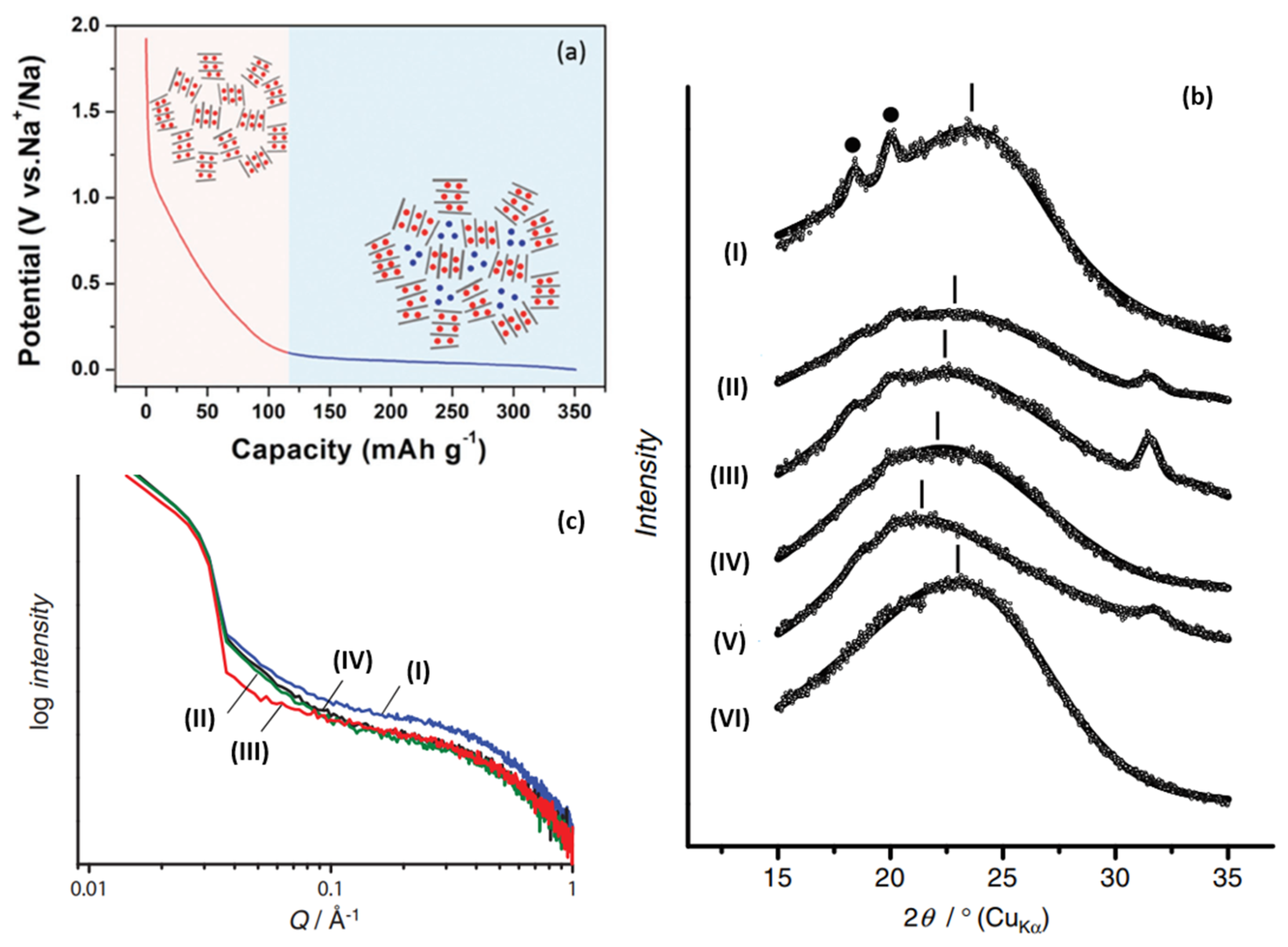
Figure 4. (a) Schematic illustration of the “intercalation-adsorption” mechanism for Sodium-ion storage in HC [36]. (b) Ex situ XRD patterns for HC electrodes: (I) pristine electrode, reduced in galvanostatic method to (II) 0.40 V, (III) 0.20 V, (IV) 0.10 V, (V) 0.00 V, and (VI) oxidized to 2.00 V after reduction to 0.00 V in 1 mol dm−1 NaClO4 PC. (• PVDF binder) [34]. (c) Ex situ SAXs patterns for HC electrodes: (I) pristine, reduced in galvanostatic method to (II) 0.20 V, (III) 0.00 V, (IV) reoxidized to 2.00 V in 1 mol dm−1 NaClO4 PC [34].
2.3.2. Adsorption-Intercalation
In 2012, Cao’s group [8] proposed a sodium storage mechanism that is completely opposite to the “intercalation-adsorption”, as shown in Figure 5a. In order to elucidate the mechanism of Sodium-ion intercalation in HC electrodes, the energy change of Sodium-ion intercalation into HC, with the change of carbon layer spacing, was simulated theoretically. It was found that the energy variation with the change of a carbon layer spacing was relatively smooth at 0.37 nm, and the intercalation of Sodium-ion at the low potential platform of 0~0.1 V was very similar to that of graphite lithium storage. Therefore, it is inferred that the low potential platform corresponds to the reversible insertion and extraction in NaCx formation (shown in Figure 5b). Furthermore, through an electrochemical impedance calculation [37], the research group showed that the diffusion coefficient of Sodium-ion in the low-potential platform region was similar to that of graphite, confirming the intercalation mechanism of the platform region.
Ji [38] regulated the structural characteristics of HC by means of heteroatom-doping and revealed the storage mechanism of Sodium-ions in the material. A high temperature annealing treatment of HC resulted in a decrease in slope capacity. High temperature annealing would remove defect sites from the surface of the material, leading to a decrease in its sodium storage capacity. Therefore, the slope capacity was attributed to the adsorption of sodium at defect sites.
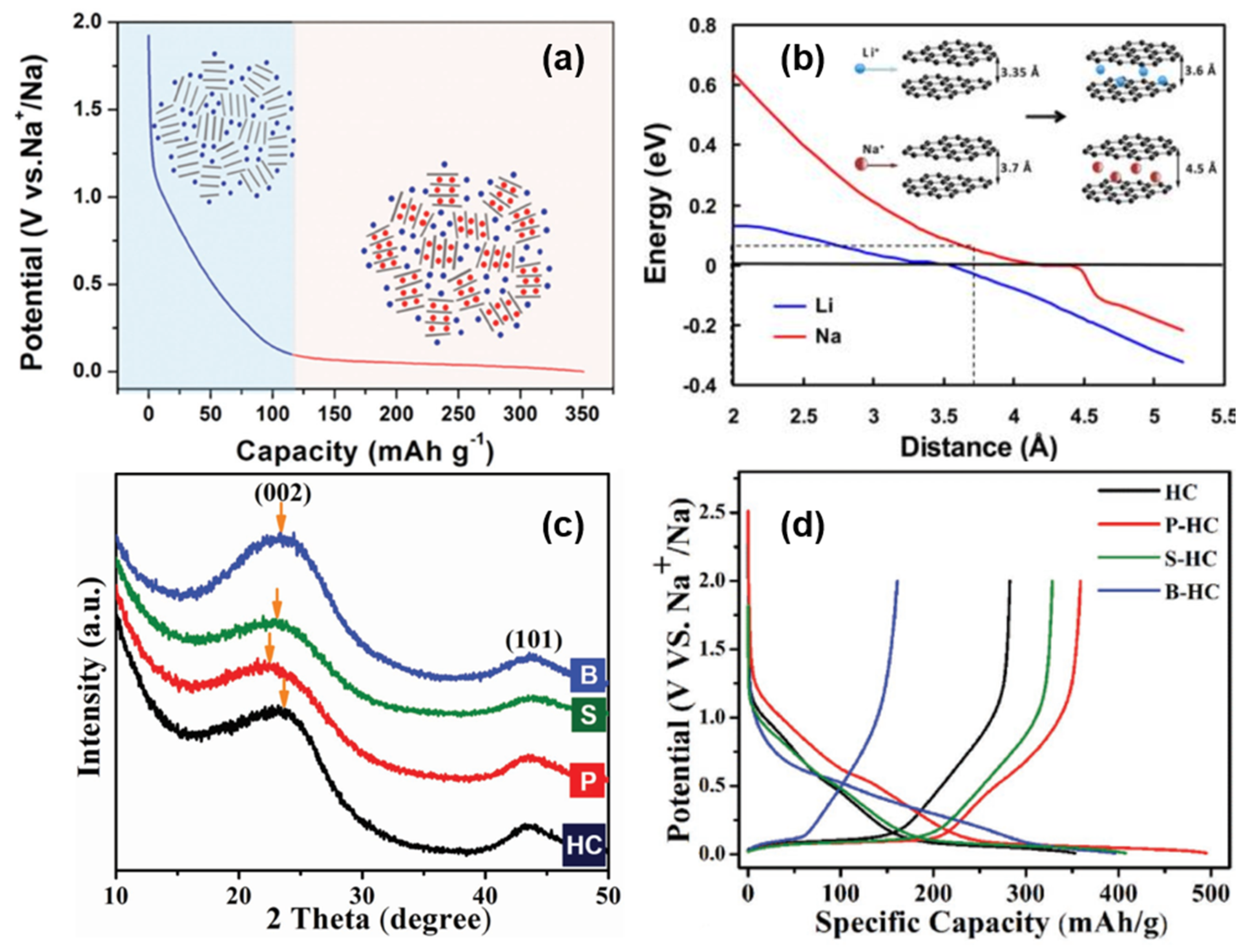
Figure 5. (a) Schematic illustration of the “adsorption-intercalation “ mechanism for Sodium-ion storage in HC [36]. (b) Theoretical energy cost for Na (red curve) and Li (blue curve) ion insertion into carbon as a function of the carbon interlayer distance. The inset illustrates the mechanism of Na and Li-ion insertion into carbon [37]. (c) XRD patterns of doped and original HCs. After P-doping and S-doping, the (002) peak shifts to a lower angle, which indicates a larger d-spacing. However, B-doping barely shifts the peak. (d) The galvanostatic sodiation and desodiation potential profiles of the original HC and doped HCs at a current rate of 20 mA g−1 [38].
Moreover, P-doping shows a high reversibility and high capacity of sodium intercalation, B-doping increases the number of defects in the carbon plane (in the absence of Lewis base, boron can only form three bonds, and its doping is more likely to occur in the carbon plane and form defect sites), and the doping of sulfur and phosphorus increase the layer spacing of the graphite microcrystalline region by means of space occupations simultaneously (shown in Figure 5c). XRD, transmission electron microscope (TEM), and energy dispersive X-ray (EDX) were applied to confirm the conjecture; P-doping and S-doping also increase the layer spacing and sodium storage capacity of the low potential platform, indicating that the corresponding mechanism is intercalation. The high defect density introduced by B increases the sodium storage capacity in the inclined region, proving that the mechanism of sodium storage in the slope region is the reversible adsorption of defect sites (shown in Figure 5d). It is worth noting that the experiment also found that the B-doping site and Sodium-ion have high binding energy, which will increase the irreversibility of adsorption, so it is necessary to avoid introducing high-energy defect sites into the structure [38].
2.3.3. Intercalation-Pore Filling
In addition to the two opposite mechanisms mentioned above, there are other sodium storage models in which there is no Sodium-ion intercalation between graphite layers in HC materials; instead, there is pore filling progress at the low potential plateau region, as shown in Figure 6a.
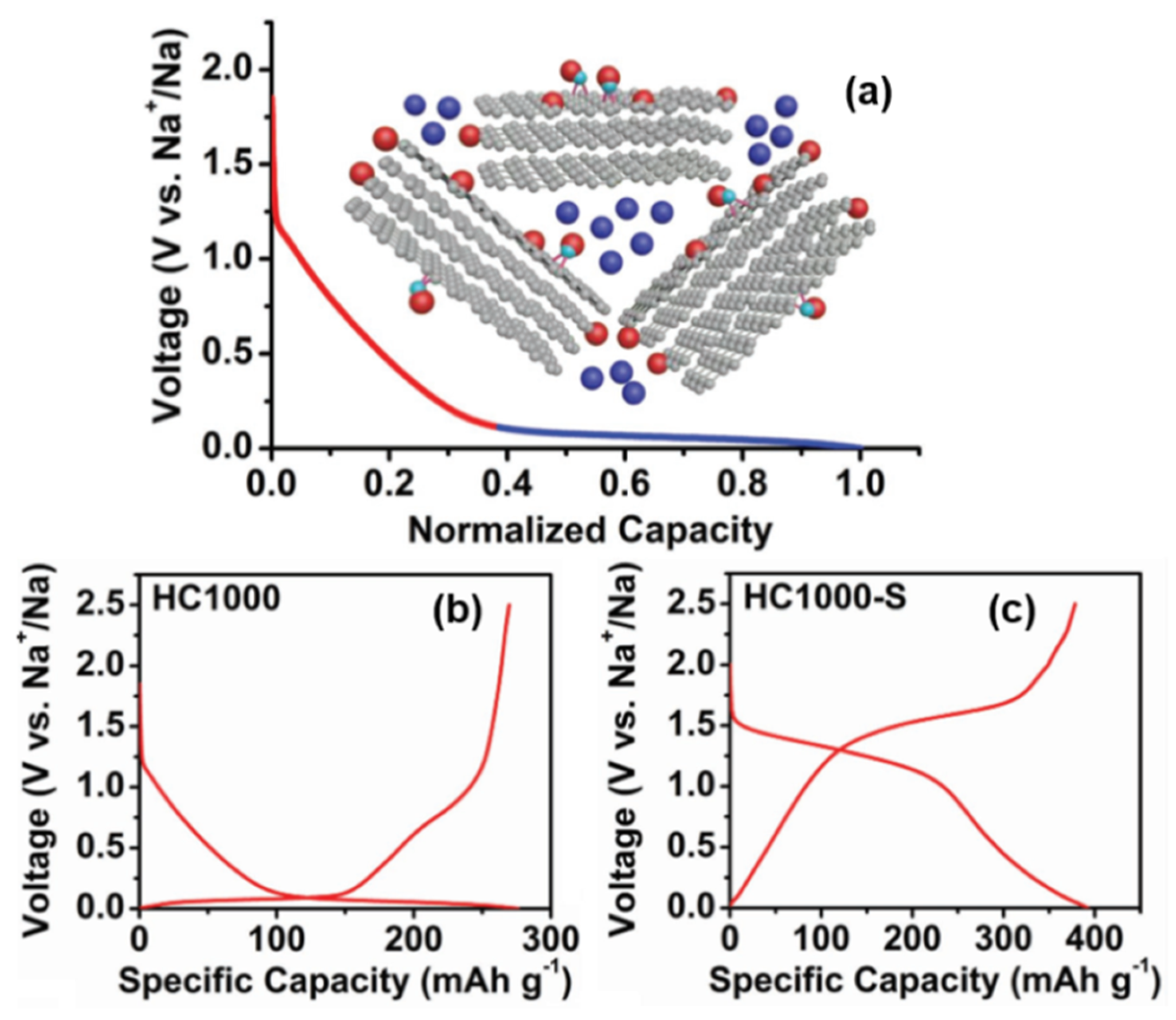
Figure 6. (a) Schematic illustration of the “adsorption-pore filling “mechanism for Sodium-ion storage in HC. (b) Galvanostatic charge and discharge curves in the 2nd cycle of 1000 °C pyrolytic HC. (c) Galvanostatic charge and discharge curves in the second cycle of 1000 °C pyrolytic HC–S composite.(in Na half-cells with 0.8M NaPF6 in DEGDME at a current density of 20 mA g−1) [39].
Xu [39] introduced an S element into the HC structure (HC–S composites were prepared by mixing and vacuum pyrolysis), and the same characteristic peak (002) of XRD indicated that sulfur did not enter the interlayer of graphite. There was no sulfur deposition on the surface of the carbon structure observed by high resolution transmission electron microscopy (HRTEM), so it was proved that sulfur was stably infused and dispersed in the microporous interval. In addition, it reduced the capacity of the platform area and provided strong evidence for the “pore filling” sodium storage mechanism of the low-potential plateau (as shown in Figure 6b,c). Their work also mentioned the correlation between the decrease in the surface defect concentration and the slope capacity, along with the effect of the electrolyte on the platform capacity; it was proven that there was no reversible Sodium-ion intercalation between the graphite sheet layers.
Hu’s group [40] also proposed a similar mechanism by adjusting the complex pore structure of a type of waste cork-derived HC. With the increase in pyrolysis temperature, one-dimensional-like morphology was formed in the pore structures, which promoted the ion transportation. The measurement results of the galvanostatic intermittent titration technique (GITT) showed that the lower the pyrolysis temperature, the lower the platform voltage and the higher the slope voltage, suggesting that the sodium storage potential is related to the microstructure of this HC (as shown in Figure 7a,b). As mentioned above, it is considered that there is no sodium intercalation process in the graphite microcrystalline region in the mechanism of sodium storage. Via mercury intrusion, nitrogen adsorption, SAXs, skeletal density techniques, various electrochemical analytical methods, and the in situ analysis of a well-designed pore structure, the correlation between the internal porous structure and the electrochemical properties of HC was obtained. Open-macropores are conducive to the stability of the carbon matrix; open-micropores have an influence on initial coulombic efficiency and closed-nanopores benefit the increase of the platform capacity; that is, they support the filling mechanism of the platform region. Besides, the filling process of sodium at this position is more complex than the deposition (such as forming metallic clusters).
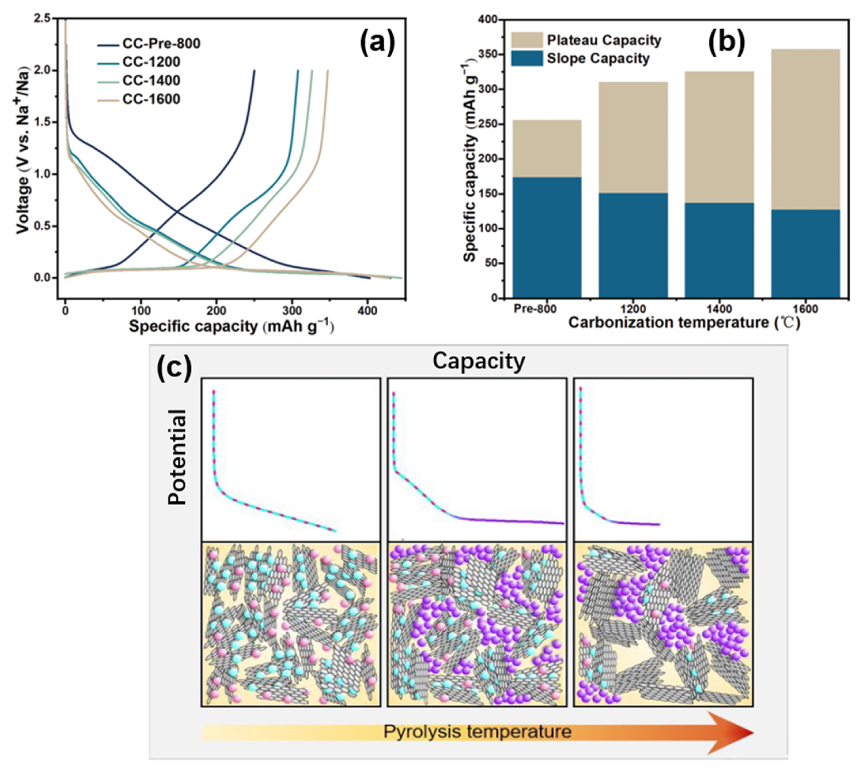
Figure 7. (a) Galvanostatic initial discharge and charge curves of cock-derived HC (prepared at different pyrolytic temperatures) at a current rate of 0.1 C (30 mA g−1). (b) Specific capacity of cock-derived HC from the different plateau (<0.15 V) and slope (>0.15 V) contributions (discharge capacity at the 2nd cycle) [40]. (c) Simple schematic illustration of the proposed sodium storage mechanism [41].
Titirici’s group [41] prepared a glucose-based HC with different internal structures by temperature regulation; the sodium storage mechanism was modified based on the intercalation-adsorption model of Dahn. It was found that pore filling occurred in the low-potential plateau region, and the pores became more metallized with the increase in pore sizes, demonstrated by ex situ 23Na nuclear magnetic resonance (NMR) spectroscopy. As Figure 7c shows, the HC with various internal structures were prepared by adjusting the temperatures from 1000~1900 °C, the schematic diagram was made by linking the characterization of materials structure with the electrochemical properties.
Relatively low pyrolysis temperatures have the highest defect concentration and the widest spacing between the sodium storage layers, although strong binding energy at some defect sites can lead to irreversible storage of sodium at these sites (also the first cycle of irreversible storage caused by the formation of an unstable solid electrolyte interphase, which is not discussed). Due to the small pore area at this time, the pore filling amount is very small, resulting in an electric potential curve that is completely composed of slope capacity. With the increase in pyrolysis temperature, the crystallinity increases, some surface defects are removed, and the interval between the layers decreases slightly. However, the storage capacity of the pores increases with the increase in pore size, so the platform area capacity appears and the slope area capacity decreases. At higher pyrolysis temperatures (about 1700~1900 °C), the number of defects plunges, so the capacity of the slope area decreases significantly. In addition, with the increase in pore size, the diffusion pathway is closed, thus some pores cannot be used for sodium storage, and it is obvious that the platform capacity also decreases. The same hypothesis was also confirmed by X-ray and neutron scattering, ex situ 23Na NMR spectroscopy, electrochemical characterization, and Density Functional Theory (DFT) simulation.
2.3.4. Adsorption-Intercalation-Pore Filling
Ji’s group [42] adopted the adsorption-intercalation theory of Dahn, and also confirmed the defect adsorption behavior in the high-potential slope region, and the Sodium-ion intercalation behavior at the low platform region in the diffusion coefficient characterization experiment of sucrose-based HC. The diffusion coefficient of the high potential zone was significantly higher than that of the low potential zone, which was attributed to the fact that the surface defects of the graphite layer preferentially adsorbed Sodium-ions, and the barrier of Sodium-ion repulsive force that needed to be overcome during the intercalation process. More importantly, as shown in Figure 8a,b, the diffusion coefficient expands significantly around 50 mV, which was likely neglected in the previous characterization and calculation [43]. Therefore, a unique nanopores filling mechanism in the region of 0~0.05 V is proposed.
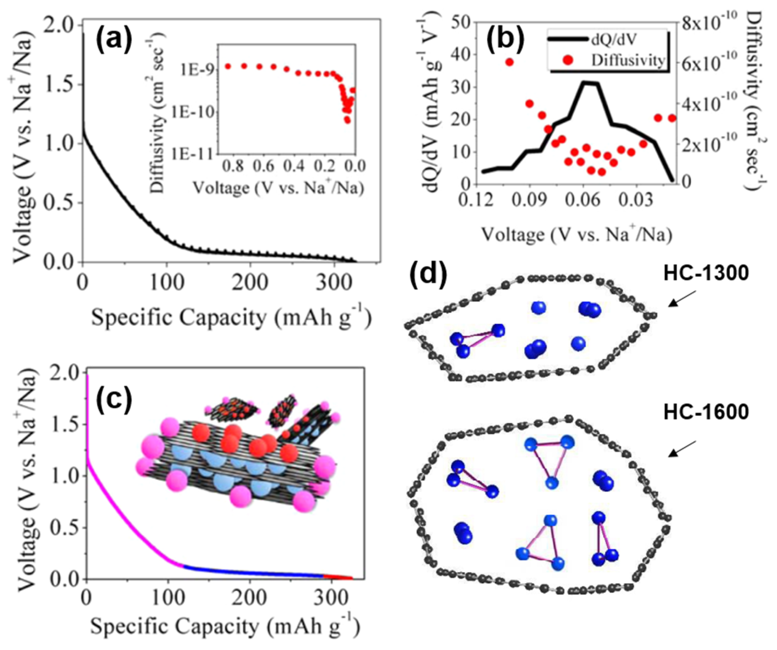
Figure 8. (a) GITT profile and diffusion coefficient as a function of states of charge (inset). (b) dQ/dV plot from 0.12 V to 0.01 V with corresponding diffusivity values within which a sudden small scale change can be observed. (c) Schematic of proposed Sodium-ion “adsorption-intercalation-pore filling” storage mechanism [42]. (d) Schematic models of sodium storage in HC nanopores of two different pyrolysis temperatures [44].
Subsequently, the state of sodium in HC was analyzed by the combination of NMR and nitrogen adsorption [44], and the storage model of quasi-metallic sodium clusters in nanopores was proposed herein (shown in Figure 8d). The pore size is limited and the storage of the Na3 clusters on the pore surface is prevented at insufficient pyrolysis temperatures (less than 1300 °C). However, at higher pyrolysis temperatures, the cost of such storage in nanopores is the decrease in surface defect concentration and a plunge in slope capacity, so such filling behavior may be minimal. The schematic diagram of the adsorption-intercalation-pore filling mechanism is shown in Figure 8c; the model has since been proven and is thought to better explain most of the results [45][46].
To sum up, the specific mechanism of sodium storage in the low-potential platform region of HC materials is still a debatable topic. The behavior of Sodium-ion insertion, pore adsorption and filling, as well as the deposition on the surfaces depends significantly on the complex HC microstructure. It requires more precise characterization and more specific structural regulation methods to reveal whether these behaviors occur simultaneously or independently. From the other aspect, the current mechanism of sodium storage in high-potential slope curves is the same, namely adsorption on material surfaces, edges, and defect sites. It is of great significance to explore the mechanism of sodium storage for directional synthesis of high-performance HC materials. As the work of Liu [36] showed, the adsorption-embedment theory was confirmed by adjusting the internal size of the material; increasing the capacity of the slope area requires maintaining a large defect density, but it will increase the irreversible influences of solid electrolyte interphase (SEI) film on ICE. Therefore, Sodium-ion intercalation with a stable voltage platform should be strengthened. Under the guidance of this understanding, a highly ordered layered structure with an appropriate layer spacing (0.37~0.38 nm) was designed in order to improve the storage capacity of sodium in the low potential platform region, which benefits the coulomb efficiency to a large extent. Eventually a non-porous HC material with a high reversible capacity and coulomb efficiency was developed and realized in practical application.
In addition, while exploring the mechanism of sodium storage, methods for regulating the HC structure, and methods for characterizing the material properties were gradually completed. Xu’s group [47] established an extended “adsorption-intercalation” model, as shown in Figure 9, dividing the evolution of the structure and the storage of sodium into five stages and three behaviors. Disordered carbons at low pyrolysis temperatures (with a layer spacing larger than 0.4 nm) tend to exhibit “pseudo-adsorption” behavior on the material surface (such as adsorption at defects, edges, heteroatomic centre and so on). Along with the temperature increasing, the disorder degree decreases, and the interval between layers is about 0.36~0.4 nm, which is enough for the Sodium-ions to achieve a reversible interlayer intercalation. At this time, the pseudo-adsorption behavior is still continuing, which is very similar to the traditional adsorption-intercalation theory. The enhanced rearrangement at high temperature leads to the deepening of the HC graphitization, and the layer spacing is below 0.36 nm, which makes it difficult to complete the insertion. The residual defects and pores on the surface attribute to the last slope capacity.
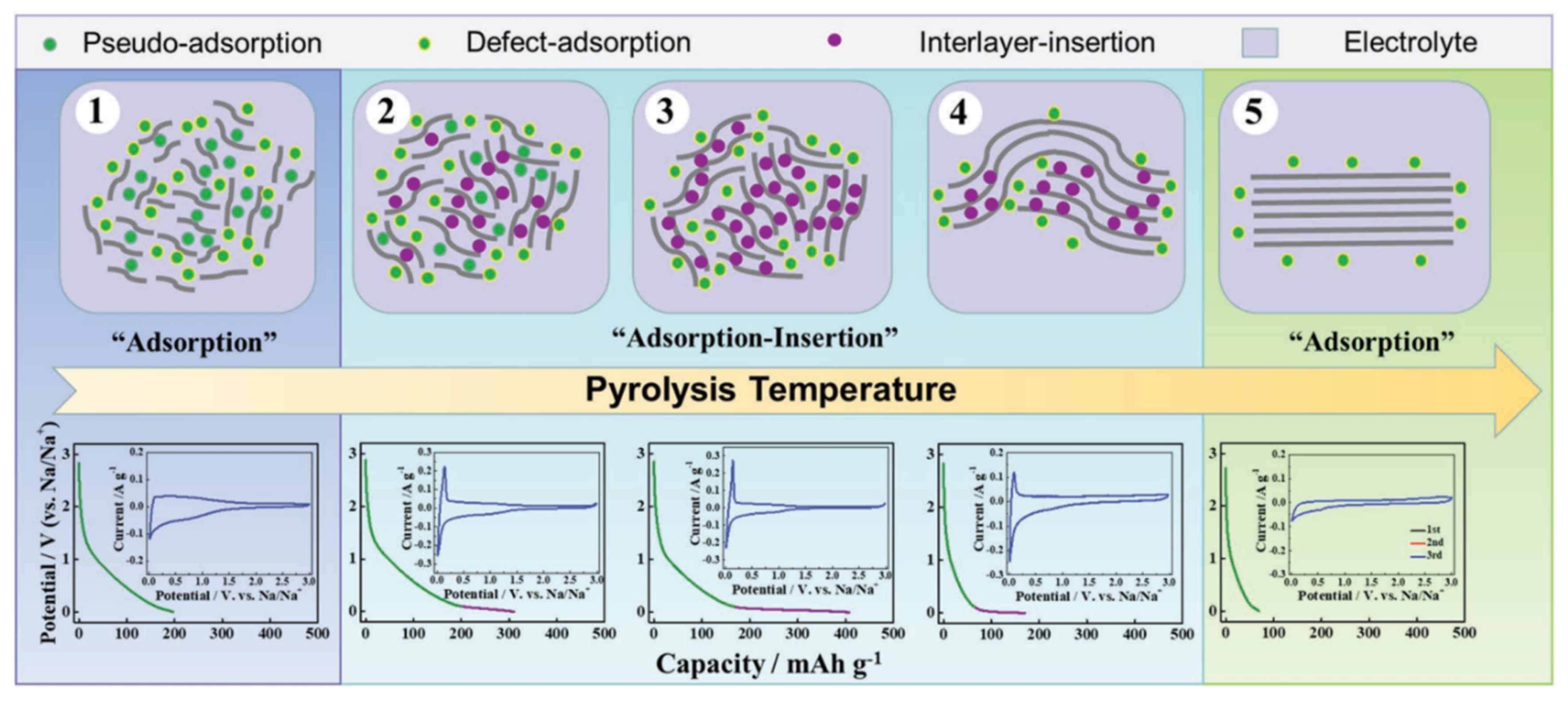
Figure 9. Schematic illustration of the extended “adsorption-intercalation” model [47].
It should be noted that the process of storing and releasing Sodium-ions is dynamic, and it may be defective to judge the sodium storage behavior of electrodes based on the experience of electrochemical kinetics alone. More accurate and visible measurement methods are needed to prove the sodium storage mechanism of HC. In summary, it is necessary to have a more comprehensive and deeper understanding of the structure of HC to reveal the sodium storage mechanism of HC materials in SIBs, to guide the controllable synthesis of anode materials, and to approach the industrialization of high-efficiency battery materials.
References
- Asenbauer, J.; Eisenmann, T.; Kuenzel, M.; Kazzazi, A.; Chen, Z.; Bresser, D. The success story of graphite as a lithium-ion anode material—Fundamentals, remaining challenges, and recent developments including silicon (oxide) composites. Sustain. Energy Fuels 2020, 4, 5387–5416.
- Nobuhara, K.; Nakayama, H.; Nose, M.; Nakanishi, S.; Iba, H. First-principles study of alkali metal-graphite intercalation compounds. J. Power Source 2013, 243, 585–587.
- Wan, J.; Shen, F.; Luo, W.; Zhou, L.; Dai, J.; Han, X.; Bao, W.; Xu, Y.; Panagiotopoulos, J.; Fan, X.; et al. In Situ Transmission Electron Microscopy Observation of Sodiation–Desodiation in a Long Cycle, High-Capacity Reduced Graphene Oxide Sodium-Ion Battery Anode. Chem. Mater. 2016, 28, 6528–6535.
- Wen, Y.; He, K.; Zhu, Y.; Han, F.; Xu, Y.; Matsuda, I.; Ishii, Y.; Cumings, J.; Wang, C. Expanded graphite as superior anode for sodium-ion batteries. Nat. Commun. 2014, 5, 4033.
- Kim, H.; Hong, J.; Park, Y.-U.; Kim, J.; Hwang, I.; Kang, K. Sodium Storage Behavior in Natural Graphite using Ether-based Electrolyte Systems. Adv. Funct. Mater. 2015, 25, 534–541.
- Jache, B.; Adelhelm, P. Use of graphite as a highly reversible electrode with superior cycle life for sodium-ion batteries by making use of co-intercalation phenomena. Angew. Chem. Int. Ed. 2014, 53, 10169–10173.
- Winter, M.; Novák, P.; Monnier, A. Graphites for Lithium-Ion Cells: The Correlation of the First-Cycle Charge Loss with the Brunauer-Emmett-Teller Surface Area. J. Electrochem. Soc. 1998, 145, 428.
- Cao, Y.; Xiao, L.; Sushko, M.; Wang, W.; Schwenzer, B.; Xiao, J.; Nie, Z.; Saraf, L.V.; Yang, Z.; Liu, J. Sodium ion insertion in hollow carbon nanowires for battery applications. Nano Lett. 2012, 12, 3783–3787.
- Yao, X.; Ke, Y.; Ren, W.; Wang, X.; Xiong, F.; Yang, W.; Qin, M.; Li, Q.; Mai, L. Defect-Rich Soft Carbon Porous Nanosheets for Fast and High-Capacity Sodium-Ion Storage. Adv. Energy Mater. 2018, 9, 1803260.
- Li, Y.; Hu, Y.-S.; Qi, X.; Rong, X.; Li, H.; Huang, X.; Chen, L. Advanced sodium-ion batteries using superior low cost pyrolyzed anthracite anode: Towards practical applications. Energy Storage Mater. 2016, 5, 191–197.
- Stevens, D.A.; Dahn, J.R. High Capacity Anode Materials for Rechargeable Sodium-Ion Batteries. J. Electrochem. Soc. 2000, 147, 1271.
- Yang, T.; Qian, T.; Wang, M.; Shen, X.; Xu, N.; Sun, Z.; Yan, C. A Sustainable Route from Biomass Byproduct Okara to High Content Nitrogen-Doped Carbon Sheets for Efficient Sodium Ion Batteries. Adv. Mater. 2016, 28, 539–545.
- Hao, R.; Yang, Y.; Wang, H.; Jia, B.; Ma, G.; Yu, D.; Guo, L.; Yang, S. Direct chitin conversion to N-doped amorphous carbon nanofibers for high-performing full sodium-ion batteries. Nano Energy 2018, 45, 220–228.
- Rath, P.C.; Patra, J.; Huang, H.; Bresser, D.; Wu, T.; Chang, J. Carbonaceous Anodes Derived from Sugarcane Bagasse for Sodium-Ion Batteries. ChemSusChem 2019, 12, 2302–2309.
- Xiao, L.; Lu, H.; Fang, Y.; Sushko, M.L.; Cao, Y.; Ai, X.; Yang, H.; Liu, J. Low-Defect and Low-Porosity Hard Carbon with High Coulombic Efficiency and High Capacity for Practical Sodium Ion Battery Anode. Adv. Energy Mater. 2018, 8, 1703238.
- Simone, V.; Boulineau, A.; de Geyer, A.; Rouchon, D.; Simonin, L.; Martinet, S. Hard carbon derived from cellulose as anode for sodium ion batteries: Dependence of electrochemical properties on structure. J. Energy Chem. 2016, 25, 761–768.
- Zhu, H.; Shen, F.; Luo, W.; Zhu, S.; Zhao, M.; Natarajan, B.; Dai, J.; Zhou, L.; Ji, X.; Yassar, R.S.; et al. Low temperature carbonization of cellulose nanocrystals for high performance carbon anode of sodium-ion batteries. Nano Energy 2017, 33, 37–44.
- Dou, X.; Hasa, I.; Saurel, D.; Jauregui, M.; Buchholz, D.; Rojo, T.; Passerini, S. Impact of the Acid Treatment on Lignocellulosic Biomass Hard Carbon for Sodium-Ion Battery Anodes. ChemSusChem 2018, 11, 3276–3285.
- Gaddam, R.R.; Niaei, A.H.F.; Hankel, M.; Searles, D.J.; Kumar, N.A.; Zhao, X.S. Capacitance-enhanced sodium-ion storage in nitrogen-rich hard carbon. J. Mater. Chem. A 2017, 5, 22186–22192.
- Sun, N.; Liu, H.; Xu, B. Facile synthesis of high performance hard carbon anode materials for sodium ion batteries. J. Mater. Chem. A 2015, 3, 20560–20566.
- Zhu, Y.; Chen, M.; Li, Q.; Yuan, C.; Wang, C. A porous biomass-derived anode for high-performance sodium-ion batteries. Carbon 2018, 129, 695–701.
- Li, Y.; Hu, Y.-S.; Titirici, M.-M.; Chen, L.; Huang, X. Hard Carbon Microtubes Made from Renewable Cotton as High-Performance Anode Material for Sodium-Ion Batteries. Adv. Energy Mater. 2016, 6, 1600659.
- Gibertini, E.; Liberale, F.; Dossi, C.; Binda, G.; Mattioli, B.; Bettinetti, R.; Maspero, A.; Fiore, M.; Ruffo, R.; Magagnin, L. Algae-derived hard carbon anodes for Na-ion batteries. J. Appl. Electrochem. 2021, 51, 1665–1673.
- Thompson, M.J.; Xia, Q.; Hu, Z.; Zhao, X.S. A review on biomass-derived hard carbon materials for sodium-ion batteries. Mater. Adv. 2021, 2, 5881–5905.
- Wang, H.-L.; Shi, Z.-Q.; Jin, J.; Chong, C.-B.; Wang, C.-Y. Properties and sodium insertion behavior of Phenolic Resin-based hard carbon microspheres obtained by a hydrothermal method. J. Electroanal. Chem. 2015, 755, 87–91.
- Bin, D.-S.; Li, Y.; Sun, Y.-G.; Duan, S.-Y.; Lu, Y.; Ma, J.; Cao, A.-M.; Hu, Y.-S.; Wan, L.-J. Structural Engineering of Multishelled Hollow Carbon Nanostructures for High-Performance Na-Ion Battery Anode. Adv. Energy Mater. 2018, 8, 1800855.
- Ding, C.; Huang, L.; Lan, J.; Yu, Y.; Zhong, W.; Yang, X. Superresilient Hard Carbon Nanofabrics for Sodium-Ion Batteries. Small 2020, 16, e1906883.
- Saurel, D.; Orayech, B.; Xiao, B.; Carriazo, D.; Li, X.; Rojo, T. From Charge Storage Mechanism to Performance: A Roadmap toward High Specific Energy Sodium-Ion Batteries through Carbon Anode Optimization. Adv. Energy Mater. 2018, 8, 1703268.
- Muñoz-Márquez, M.; Saurel, D.; Gómez-Cámer, J.L.; Casas-Cabanas, M.; Castillo-Martínez, E.; Rojo, T. Na-Ion Batteries for Large Scale Applications: A Review on Anode Materials and Solid Electrolyte Interphase Formation. Adv. Energy Mater. 2017, 7, 1700463.
- Saurel, D.; Segalini, J.; Jauregui, M.; Pendashteh, A.; Daffos, B.; Simon, P.; Casas-Cabanas, M. A SAXS outlook on disordered carbonaceous materials for electrochemical energy storage. Energy Storage Mater. 2019, 21, 162–173.
- Dou, X.; Hasa, I.; Saurel, D.; Vaalma, C.; Wu, L.; Buchholz, D.; Bresser, D.; Komaba, S.; Passerini, S. Hard carbons for sodium-ion batteries: Structure, analysis, sustainability, and electrochemistry. Mater. Today 2019, 23, 87–104.
- Emmerich, F.G. Evolution with heat treatment of crystallinity in carbons. Carbon 1995, 33, 1709–1715.
- Stevens, D.A.; Dahn, J.R. The Mechanisms of Lithium and Sodium Insertion in Carbon Materials. J. Electrochem. Soc. 2001, 148, A803.
- Komaba, S.; Murata, W.; Ishikawa, T.; Yabuuchi, N.; Ozeki, T.; Nakayama, T.; Ogata, A.; Gotoh, K.; Fujiwara, K. Electrochemical Na Insertion and Solid Electrolyte Interphase for Hard-Carbon Electrodes and Application to Na-Ion Batteries. Adv. Funct. Mater. 2011, 21, 3859–3867.
- Irisarri, E.; Ponrouch, A.; Palacin, M.R. Review—Hard Carbon Negative Electrode Materials for Sodium-Ion Batteries. J. Electrochem. Soc. 2015, 162, A2476–A2482.
- Qiu, S.; Xiao, L.; Sushko, M.L.; Han, K.S.; Shao, Y.; Yan, M.; Liang, X.; Mai, L.; Feng, J.; Cao, Y.; et al. Manipulating Adsorption–Insertion Mechanisms in Nanostructured Carbon Materials for High-Efficiency Sodium Ion Storage. Adv. Energy Mater. 2017, 7, 1700403.
- Xiao, L.; Cao, Y.; Henderson, W.A.; Sushko, M.L.; Shao, Y.; Xiao, J.; Wang, W.; Engelhard, M.H.; Nie, Z.; Liu, J. Hard carbon nanoparticles as high-capacity, high-stability anodic materials for Na-ion batteries. Nano Energy 2016, 19, 279–288.
- Li, Z.; Bommier, C.; Chong, Z.S.; Jian, Z.; Surta, T.W.; Wang, X.; Xing, Z.; Neuefeind, J.C.; Stickle, W.F.; Dolgos, M.; et al. Mechanism of Na-Ion Storage in Hard Carbon Anodes Revealed by Heteroatom Doping. Adv. Energy Mater. 2017, 7, 1602894.
- Bai, P.; He, Y.; Zou, X.; Zhao, X.; Xiong, P.; Xu, Y. Elucidation of the Sodium-Storage Mechanism in Hard Carbons. Adv. Energy Mater. 2018, 8, 1703217.
- Li, Y.; Lu, Y.; Meng, Q.; Jensen, A.C.S.; Zhang, Q.; Zhang, Q.; Tong, Y.; Qi, Y.; Gu, L.; Titirici, M.; et al. Regulating Pore Structure of Hierarchical Porous Waste Cork-Derived Hard Carbon Anode for Enhanced Na Storage Performance. Adv. Energy Mater. 2019, 9, 1902852.
- Au, H.; Alptekin, H.; Jensen, A.C.S.; Olsson, E.; O’Keefe, C.A.; Smith, T.; Crespo-Ribadeneyra, M.; Headen, T.F.; Grey, C.P.; Cai, Q.; et al. A revised mechanistic model for sodium insertion in hard carbons. Energy Environ. Sci. 2020, 13, 3469–3479.
- Bommier, C.; Surta, T.W.; Dolgos, M.; Ji, X. New Mechanistic Insights on Na-Ion Storage in Nongraphitizable Carbon. Nano Lett 2015, 15, 5888–5892.
- Bommier, C.; Ji, X.; Greaney, P.A. Electrochemical Properties and Theoretical Capacity for Sodium Storage in Hard Carbon: Insights from First Principles Calculations. Chem. Mater. 2018, 31, 658–677.
- Morita, R.; Gotoh, K.; Fukunishi, M.; Kubota, K.; Komaba, S.; Nishimura, N.; Yumura, T.; Deguchi, K.; Ohki, S.; Shimizu, T.; et al. Combination of solid state NMR and DFT calculation to elucidate the state of sodium in hard carbon electrodes. J. Mater. Chem. A 2016, 4, 13183–13193.
- Morikawa, Y.; Nishimura, S.; Hashimoto, R.; Ohnuma, M.; Yamada, A. Mechanism of Sodium Storage in Hard Carbon: An X-Ray Scattering Analysis. Adv. Energy Mater. 2019, 10, 1903176.
- Wang, Z.; Feng, X.; Bai, Y.; Yang, H.; Dong, R.; Wang, X.; Xu, H.; Wang, Q.; Li, H.; Gao, H.; et al. Probing the Energy Storage Mechanism of Quasi-Metallic Na in Hard Carbon for Sodium-Ion Batteries. Adv. Energy Mater. 2021, 11, 2003854.
- Sun, N.; Guan, Z.; Liu, Y.; Cao, Y.; Zhu, Q.; Liu, H.; Wang, Z.; Zhang, P.; Xu, B. Extended “Adsorption–Insertion” Model: A New Insight into the Sodium Storage Mechanism of Hard Carbons. Adv. Energy Mater. 2019, 9, 1901351.
More
Information
Contributors
MDPI registered users' name will be linked to their SciProfiles pages. To register with us, please refer to https://encyclopedia.pub/register
:
View Times:
2.3K
Revisions:
2 times
(View History)
Update Date:
21 Oct 2022
Table of Contents


Notice
You are not a member of the advisory board for this topic. If you want to update advisory board member profile, please contact office@encyclopedia.pub.
OK
Confirm
Only members of the Encyclopedia advisory board for this topic are allowed to note entries. Would you like to become an advisory board member of the Encyclopedia?
Yes
No
${ textCharacter }/${ maxCharacter }
Submit
Cancel
Back
Comments
${ item }
|
${ item.createdUser.fullName }
${ item.createdAt }
${ item.vote }
${ item.reply }
Delete
${ reply.createdUser.fullName }
${ reply.createdAt }
${ reply.vote }
Delete
There is no reply to this comment~
${ item.replyTextCharacter }/${ item.replyMaxCharacter }
Submit
Cancel
More
No more~
There is no comment~
${ textCharacter }/${ maxCharacter }
Submit
Cancel
${ selectedItem.replyTextCharacter }/${ selectedItem.replyMaxCharacter }
Submit
Cancel
Confirm
Are you sure to Delete?
Yes
No