| Version | Summary | Created by | Modification | Content Size | Created at | Operation |
|---|---|---|---|---|---|---|
| 1 | Camila Xu | -- | 2451 | 2022-10-20 01:45:11 |
Video Upload Options
Spiral ground heat exchangers in heat pump applications play an important role in heating/cooling of buildings. Energy consumption of buildings is a significant factor in global environmental issues. One of the ways of supplying heating and cooling is using potential energy stored in the ground which is clean and sustainable. These types of systems are called ground source heat pump (GSHP) systems. The initial cost and efficiency of GSHP systems can be influenced by optimal design of ground heat exchangers (GHEs). Many parameters influencing thermal performance of spiral GHEs such as external major diameter of borehole, spacing, distance between each turns of spiral GHEs, etc. When we have a large application area, one spiral GHE is not enough for supplying heating or cooling demands of the building. In this case more than one GHE is needed to be embedded into the ground. When we have more than one GHE in ground, optimization of distance between them becomes an essential problem. Another important parameter which is highly affecting thermal performance of a GSHP system are thermal properties of ground. Before integrating a GSHP system to the building thermal properties of ground or soil should be determined.
1. Introduction
Air contamination is one of the significant environmental concerns in the world. Reaching solutions to environmental problems that we face today needs long term activities for sustainable development. Renewable energy sources seem to be one of the best and effective solutions.[1] In recent decades, energy consumption for building has increased and many efforts are being done to investigate alternative energy sources for supplying heating and cooling demands of building. One of the best alternative ways is the use of ground energy, which is clean, green and sustainable. This energy can be utilized through GSHP system, which is well established in most of the European countries for space heating applications.[2] GSHP systems contain two main parts, GHEs and heat pump.
In these systems, heat source is soil that stored huge amount of energy inside. When fluid/water stars flowing inside pipelines heat is transferred from fluid to the soil or from soil to the fluid due to the temperature difference between them. Research indicates that temperature of ground is constant after 6-meter depth. This means that temperature at ground surface is not affecting temperature of soil after 6-meter depth.[3]
As an example, assume that fluid is pumped into the ground at 40 °C and undisturbed ground temperature is 18 °C. As the time passes, temperature of soil around spiral GHEs will be increased and then there will be less heat transfer between pumped fluid and soil due to the low temperature difference. In the case of deep GHEs, temperature of exhausted fluid is too high. In this case, these types of GHEs can be used directly for supplying heating demands of the building.[3]
1.1. Heat Pump
As it was stated, heat is transferred from high to low temperature medium without needing any external devices. But in many cases heated is needed to be transferred reversely. Heat pumps are devices which receive heat from low temperature and deliver it to a higher temperature reservoir. Working procedure of refrigerators and heat pumps are the same and only the purposes of their use are different.[4] A heat pump can also extract heat from a heat source and reject heat to air and water at the higher temperature for heating. One of the important parameters for heat pumps is coefficient of performance (COP) of it. Definition of COP is desired output per desired input of the device.[5]
1.2. Ground Source Heat Pump Systems
Ground source heat pumps (GSHP) or geothermal heat pumps are heating/cooling devices that use ground as their heat source. GSHPs offer significant reductions of electrical energy use, cheap levels of maintenance requirements, and are environment friendly. A ground source heat pump is a heating and cooling system that transfers heat to or from the ground, using the ground as a heat sink in the summer and heat source in the winter. A ground source heat pump can be significantly more energy efficient than conventional air source heat pump.[6] As it was discussed, GSHP systems consist of two main parts, heat pump and ground heat exchangers.
1.3. Ground Heat Exchanger
Ground heat exchangers use underground soil as a heat source. When water/fluid flows through pipes, heat is transferred from the water to the soil or from soil to the fluid depending on the temperature of fluid and its surrounding temperature. GHEs have some classifications such as deep, shallow, open loop, closed loop, etc.[3] Choosing correct types of GHEs is highly depending on geological properties of application area. For instance underground fluid flow or having a lake near application area could be very important advantages.[7] Heat is transferred in the ground by two ways, convection and conduction.[3]
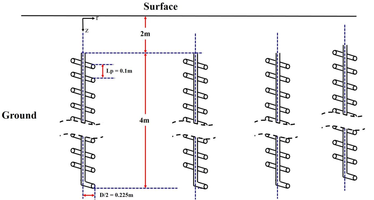
As it was discussed, several types of GHEs such as shallow and deep ones exist. Deep GHEs are generally U-tube GHEs with common ranges of 50-200 meter. Shallow GHEs are divided to spiral, slinky, pond/lake and snails types. Among different types of shallow GHEs spiral ones show the best performance in the same application unit area which means that more amount of heat can be extracted or injected into the ground. This also means that more space area of the building could be heated or cooled by spiral GHEs. Spiral GHEs are favorable due to their high efficiencies and low initial costs. When spiral GHEs are connected to the heat pump system and total system (GSHP) is integrated to the buildings, heating/cooling demands of that specific residential building could be supplied easily by spiral GHEs. Many pieces of research show that when nine numbers of spiral GHEs are connected to the heat pump system, heating demands of at least 200 square meter space area of a building could be supplied. Based on different parameters of spiral GHEs this value could be changed between 200–800 square meter space area. In Fig. 1 schematic view of a series of spiral GHEs are shown.[3]
Heat transfer rate of GHEs is depending on several parameters such as thermal conductivity of soil or application area, thermal properties of fluid, peripheral area of GHEs and flow rate of fluid inside GHEs. When we have spiral GHEs it means that we have more peripheral area of heat exchanger and so we have more heat transfer. Or for pond/lake types GHEs, since we have fluid around heat exchangers this means that we will have more heat transfer and more temperature difference between inlet and outlet fluid. This issue is one of the most important advantages of pond/lake GHEs.[3]
2. Integration of Spiral GHEs to the Building
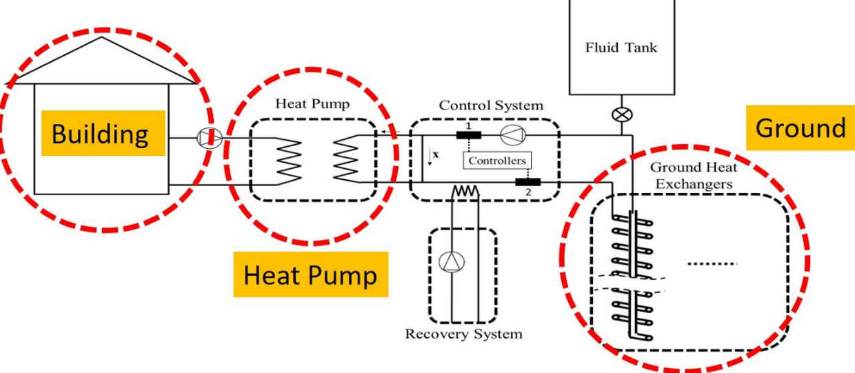
Fig. 2 shows integration of a GSHP system to the building. As it is shown in this figure, heat is extracted from ground by spiral GHEs. After extraction process, fluid enters a controller to control inlet and out fluid temperature of the machine. After that fluid will enter heat pump system and supply required heating/cooling demands of the building. To calculate the effective amount of space area that can be heated or cooled by GSHP system different parameters are needed. These parameters are amount of extracted/injected heat from/to ground by spiral GHEs, coefficient of performance (COP) of heat pump, heating and cooling loads of the building[8]
Different researches show that distance between spiral GHEs greatly affects the performance of a GSHP system. It means that the distance between them should be optimized well. By choosing low distance between them (less that 5 meter) there will be high performance loss in system and suitable amount of heat cannot be delivered or rejected from building.[9]
2.1. Optimization of Distance between Spiral GHEs
As it is known, concept of extracting/injecting heat from/to ground is temperature different between two mediums. When there are more than one spiral GHEs embedded in ground it means that we have more thermal interactions in ground. When distance between heat exchangers is low (lower than 5 meters) thermal interactions between them is also too high. By increasing the distance between them thermal interactions will be reduced and therefore we have low performance loss in the system. Different researches show that at least 6/7 meter distance must be chosen between GHEs. For example, when number of spiral GHEs is nine we have 15%, 18%, 22% performance loss for 7, 6 and 5 meter distance between them respectively.[10]
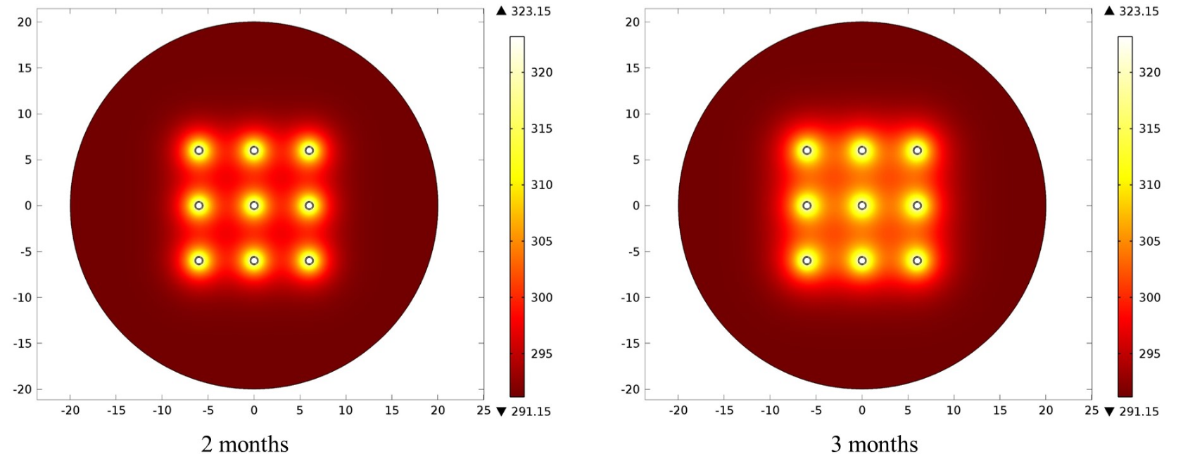
In ground source heat pump applications, optimization of distance between GHEs plays an important role in total performance of the system. This value also should be chosen based the availability of application area and also investors needs. In Fig. 3 thermal interactions between nine numbers of spiral GHEs are shown. As it is demonstrated as the time passes thermal interactions between spiral GHEs are increased.[10]
2.2. The Effects of the Pitch Distance (Lp) and Major Diameter (D) of a Single Vertical Spiral GHE on Its Performance
The distance between each turns of the spiral and GHE major radius play a crucial role in the design process. These parameters are geometrical parameters that are influencing initial cost and thermal performance of GHEs. These properties are directly related to the vertical lengths required to construct the heat exchanger as well as amount of excavation.[10] It is seen that by increasing the Lp and D, HTR value of a GHE is improved. On the other hand, the total cost of embedding the GHE into ground becomes higher and higher by increasing the values of Lp and D. Therefore, it is important for designers and investors that they know the exact requirements of consumers.[10]
The improvement of HTR value with longer and bigger exchangers results in increment of installation costs, which are the main drawback of GSHPs. During the designing of GHE fields, maximum heat load of the consumer is considered, and the minimum required borehole sizes (Lp and D) are chosen. On the other hand, trying to minimize the installation cost by decreasing the sizes of Lp and D alone, causes higher number of GHE which also increases the initial cost. Therefore, initial cost should be minimized by considering the whole system. Furthermore, not only the initial cost but also the operational costs should be considered during the optimization of the system overall costs. This requires the long term predictions of HTR value of a GHE. Results show that the average HTR values linearly increase with the value of D and Lp. These linear dependencies are due to the increment of peripheral surface area and heat capacity of ground per turn.[10]
2.3. A Typical Example for Vertical Spiral GHE Analysis
In this part, a building with 120 m2 heating/cooling area is considered. For heating and cooling of this building, GSHP system with vertical spiral GHE is chosen. As it is stated in different references, general required heat load for a standard building is approximately 80 W/m2. Therefore, total heat load of this building is 9600 W. Furthermore, COP value of a heat pump is assumed as 4.0. In this case, 7200 W heat is needed to pump from ground to building. To predict the number of GHEs that are needed for heating and cooling applications, first of all long term performance of a single vertical spiral GHE should be estimated. Again by using COMSOL and based on previous validated data, HTR value of a single vertical spiral GHE is numerically predicted. The averaged HTR value is around 870 W for 1–6 months time interval.
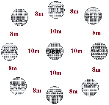
In GHE designing procedure generally the most critical conditions are considered. The system is assumed to work 6 months non-stop in heating or cooling mode. For 6 month operation, COMSOL results show that averaged HTR of a single vertical spiral GHE is 870 W. By taking all the above arguments into consideration it is concluded that 9 vertical spiral GHE is needed for this building. For more than 5 GHEs, we assume that five GHEs graph can be used for performance loss prediction with an acceptable error. By looking at figures in relevant literature, ten meter distances between GHEs are chosen. For this distance, performance loss is less than 5%. Based on consumers utilization and designers' goals this amount can of course vary. The suggested configuration is shown in Fig. 4 for most critical conditions (6 months non-stop operation). In this configuration, performance loss is predicted less than 5%.[10]
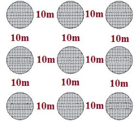
Sometimes the application area is limited and there is no enough space for placing GHEs. In that case, more performance losses can be accepted to minimize the application area. For nine vertical spiral GHEs, the following configuration can also be used. In corners and sides we can use three GHEs performance loss graph. Figure 5 demonstrates other configuration of nine spiral GHEs that can be used.[10]
3. Beneficial Use of Some Environmental Waste Energy Through Spiral GHEs
Nowadays keeping our environment clean is one of the most important issues. There are still many waste heat and energies that are wasted into the environment such as, waste heat of gas turbines exhaust gasses or waste gasses in biomass systems. These waste heats can be used beneficially for supplying heating demands of the buildings. One way to use this energy usefully is to store it in ground and then re-extract it through spiral GHEs for providing heating demands of the buildings. Recent researches show that spiral GHEs could be one of the best choices. First waste heat could be stored in ground by spiral GHEs and then extracted by them. Ground has ability to store this energy in ground for a long period. Also, results of different researches show that amount of space area that can be heated by GSHP system is multiplied by four.[11]
4. General Discussion about Spiral GHEs
This short article presents the analyses of various parameters on the efficiency of spiral GHE for GSHP systems. The most important parameters, which influence the performance of GSHPs, have been thoroughly analyzed, running long-term simulations and estimating the performance losses for each GHE configuration. The results prove that Lp and D are one of the important parameters in the design of a GSHP. Although increasing these parameters can improve the efficiency of GSHP, a larger investment is needed for installation. Therefore, an optimum length should be found, which minimizes the total cost over the plant lifetime for an acceptable performance value.[10]
In the large number of GHE, one of the most essential parameters that affect the system performance is distance between GHEs. The performance losses are less than 5% if the distance between GHE is more than 5 m, 7 m and 9 m for 2, 3 and 5 GHEs configuration. Therefore, spiral GHEs could be one good choice for storing environmental waste energy in the ground and then re-utilize it.[10]
References
- Wood, C.J., Liu, H., Riffat (2010). "An investigation of the heat pump performance and ground temperature of a pile foundation heat exchanger system for a residential building". Energy 35: 32–40.
- Bakirci, K. (2010). "Evaluation of the performance of a ground-source heat pump system with series GHE (ground heat exchanger) in the cold climate region". Energy 35 (7): 3088–3096. doi:10.1016/j.energy.2010.03.054. https://dx.doi.org/10.1016%2Fj.energy.2010.03.054
- Banks, David (2008). An introduction to thermogeology: ground source heating and cooling. Blackwell Publishing.
- Çengel, Y., Boles, M.A. (2011). Thermodynamics: An engineering approach (7th ed.). New York: McGraw-Hill.
- Ingley, H. A., Wang, S. K., Rabl, A. (2005). Air Conditioning and Refrigeration (2nd ed.). Atlanta, US: CRC Press.
- Ascione, F., Bellia, L., Minichiello, F. (2011). "Earth-to-air heat exchangers for Italian climates". Renewable Energy 36 (8): 2177–2188. doi:10.1016/j.renene.2011.01.013. https://dx.doi.org/10.1016%2Fj.renene.2011.01.013
- Florides, G., Kalogrirou, S. (2007). "Ground heat exchanger-A review of system model and applications". Renewable Energy 32: 2461–2478. doi:10.1016/j.renene.2006.12.014. https://dx.doi.org/10.1016%2Fj.renene.2006.12.014
- Dehghan B., Babak (2018). "Effectiveness of using spiral ground heat exchangers in ground source heat pump system of a building for district heating/cooling purposes: Comparison among different configurations". Applied Thermal Engineering 130: 1489–1506. doi:10.1016/j.applthermaleng.2017.11.124. https://dx.doi.org/10.1016%2Fj.applthermaleng.2017.11.124
- Dehghan, Babak (2016). "Parametric investigation of helical ground heat exchangers for heat pump applications". Energy and Buildings 127: 999–1007. doi:10.1016/j.enbuild.2016.06.064. https://dx.doi.org/10.1016%2Fj.enbuild.2016.06.064
- Dehghan B., Babak (2017). "Experimental and computational investigation of the spiral ground heat exchangers for ground source heat pump applications". Applied Thermal Engineering 121: 908–921. doi:10.1016/j.applthermaleng.2017.05.002. https://dx.doi.org/10.1016%2Fj.applthermaleng.2017.05.002
- Dehghan B., Babak (2017). "Performance assessment of ground source heat pump system integrated with micro gas turbine: Waste heat recovery". Energy Conversion and Management 152: 328–341. doi:10.1016/j.enconman.2017.09.058. https://dx.doi.org/10.1016%2Fj.enconman.2017.09.058


