 +1 credit
| Version | Summary | Created by | Modification | Content Size | Created at | Operation |
|---|---|---|---|---|---|---|
| 1 | Dean Liu | -- | 1867 | 2022-10-17 01:49:32 |
Video Upload Options
In electrical engineering, three-phase electric power systems have at least three conductors carrying alternating current voltages that are offset in time by one-third of the period. A three-phase system may be arranged in delta (∆) or star (Y) (also denoted as wye in some areas). A wye system allows the use of two different voltages from all three phases, such as a 230/400 V system which provides 230 V between the neutral (centre hub) and any one of the phases, and 400 V across any two phases. A delta system arrangement only provides one voltage magnitude, but it has a greater redundancy as it may continue to operate normally with one of the three supply windings offline, albeit at 57.7% of total capacity. Harmonic current in the neutral may become very large if nonlinear loads are connected.
1. Definitions
In a star (wye) connected topology, with rotation sequence L1 - L2 - L3, the time-varying instantaneous voltages can be calculated for each phase A,C,B respectively by:
- [math]\displaystyle{ V_{L1-N} = V_P \sin\left(\theta\right)\,\! }[/math]
- [math]\displaystyle{ V_{L2-N} = V_P \sin\left(\theta - \frac{2}{3}\pi\right) = V_P \sin\left(\theta + \frac{4}{3}\pi\right) }[/math]
- [math]\displaystyle{ V_{L3-N} = V_P \sin\left(\theta - \frac{4}{3}\pi\right) = V_P \sin\left(\theta + \frac{2}{3}\pi\right) }[/math]
where:
- [math]\displaystyle{ V_P }[/math] is the peak voltage,
- [math]\displaystyle{ \theta = 2\pi ft\,\! }[/math] is the phase angle in radians
- [math]\displaystyle{ t }[/math] is the time in seconds
- [math]\displaystyle{ f }[/math] is the frequency in cycles per second and
- voltages L1-N, L2-N and L3-N are referenced to the star connection point.
2. Diagrams
The below images demonstrate how a system of six wires delivering three phases from an alternator may be replaced by just three. A three-phase transformer is also shown.
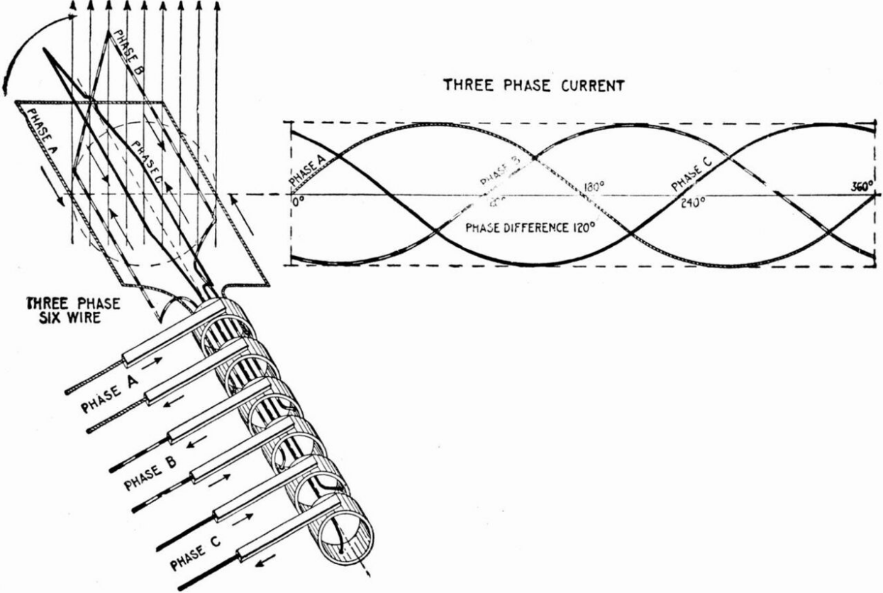
Elementary six-wire three-phase alternator, with each phase using a separate pair of transmission wires. https://handwiki.org/wiki/index.php?curid=1549121
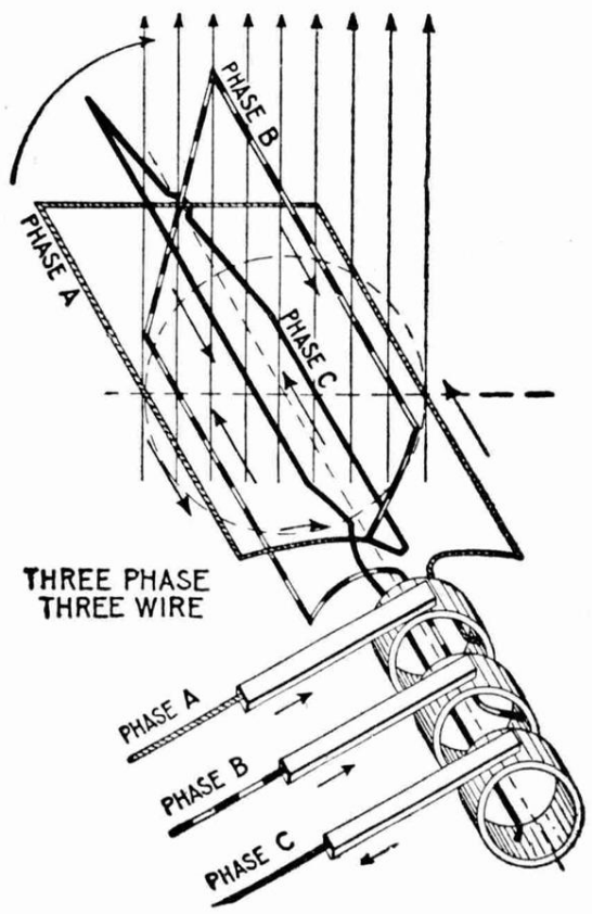
Elementary three-wire three-phase alternator, showing how the phases can share only three transmission wires. https://handwiki.org/wiki/index.php?curid=1837639
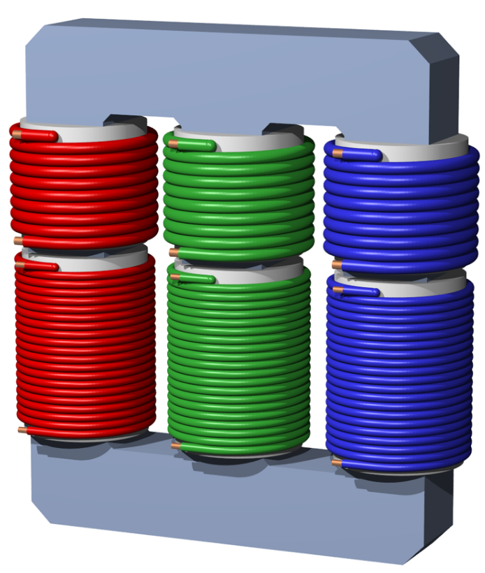
Three-phase transformer. Each phase has its own pair of windings. https://handwiki.org/wiki/index.php?curid=1297329
3. Balanced Loads
Generally, in electric power systems, the loads are distributed as evenly as is practical between the phases. It is usual practice to discuss a balanced system first and then describe the effects of unbalanced systems as deviations from the elementary case.
3.1. Constant Power Transfer
An important property of three-phase power is that the instantaneous power available to a resistive load, [math]\displaystyle{ \scriptstyle P \,=\, V I \,=\, \frac{1}{R}V^2 }[/math], is constant at all times. Indeed, let
- [math]\displaystyle{ \begin{align} P_{Li} &= \frac{V_{Li}^{2}}{R} \\ P_{TOT} &= \sum_i P_{Li} \end{align} }[/math]
To simplify the mathematics, we define a nondimensionalized power for intermediate calculations, [math]\displaystyle{ \scriptstyle p \,=\, \frac{1}{V_P^2}P_{TOT} R }[/math]
- [math]\displaystyle{ p=\sin^{2} \theta+\sin^{2} \left(\theta-\frac{2}{3} \pi\right)+\sin^{2} \left(\theta-\frac{4}{3} \pi\right)=\frac{3}{2} }[/math]
Hence (substituting back):
- [math]\displaystyle{ P_{TOT}=\frac{3 V_P^2}{2R}. }[/math]
Since we have eliminated [math]\displaystyle{ \theta }[/math] we can see that the total power does not vary with time. This is essential for keeping large generators and motors running smoothly.
Notice also that using the root mean square voltage [math]\displaystyle{ V = \frac{V_p}{\sqrt{2}} }[/math], the expression for [math]\displaystyle{ P_{TOT} }[/math] above takes the following more classic form:
- [math]\displaystyle{ P_{TOT} = \frac{3V^2}{R} }[/math].
The load need not be resistive for achieving a constant instantaneous power since, as long as it is balanced or the same for all phases, it may be written as
- [math]\displaystyle{ Z=|Z|e^{j\varphi} }[/math]
so that the peak current is
- [math]\displaystyle{ I_P=\frac{V_P}{|Z|} }[/math]
for all phases and the instantaneous currents are
- [math]\displaystyle{ I_{L1}=I_P\sin\left(\theta-\varphi\right) }[/math]
- [math]\displaystyle{ I_{L2}=I_P\sin\left(\theta-\frac{2}{3}\pi-\varphi\right) }[/math]
- [math]\displaystyle{ I_{L3}=I_P\sin\left(\theta-\frac{4}{3}\pi-\varphi\right) }[/math]
Now the instantaneous powers in the phases are
- [math]\displaystyle{ P_{L1}=V_{L1}I_{L1}=V_P I_P\sin\left(\theta\right)\sin\left(\theta-\varphi\right) }[/math]
- [math]\displaystyle{ P_{L2}=V_{L2}I_{L2}=V_P I_P\sin\left(\theta-\frac{2}{3}\pi\right)\sin\left(\theta-\frac{2}{3}\pi-\varphi\right) }[/math]
- [math]\displaystyle{ P_{L3}=V_{L3}I_{L3}=V_P I_P\sin\left(\theta-\frac{4}{3}\pi\right)\sin\left(\theta-\frac{4}{3}\pi-\varphi\right) }[/math]
Using angle subtraction formulae:
- [math]\displaystyle{ P_{L1}=\frac{V_P I_P}{2}\left[\cos\left(\varphi\right)-\cos\left(2\theta-\varphi\right)\right] }[/math]
- [math]\displaystyle{ P_{L2}=\frac{V_P I_P}{2}\left[\cos\left(\varphi\right)-\cos\left(2\theta-\frac{4}{3}\pi-\varphi\right)\right] }[/math]
- [math]\displaystyle{ P_{L3}=\frac{V_P I_P}{2}\left[\cos\left(\varphi\right)-\cos\left(2\theta-\frac{8}{3}\pi-\varphi\right)\right] }[/math]
which add up for a total instantaneous power
- [math]\displaystyle{ P_{TOT}=\frac{V_P I_P}{2}\left\{3\cos\varphi-\left[\cos\left(2\theta-\varphi\right)+\cos\left(2\theta-\frac{4}{3}\pi-\varphi\right)+\cos\left(2\theta-\frac{8}{3}\pi-\varphi\right)\right]\right\} }[/math]
Since the three terms enclosed in square brackets are a three-phase system, they add up to zero and the total power becomes
- [math]\displaystyle{ P_{TOT}=\frac{3V_P I_P}{2}\cos\varphi }[/math]
or
- [math]\displaystyle{ P_{TOT}=\frac{3V_P^2}{2|Z|}\cos\varphi }[/math]
showing the above contention.
Again, using the root mean square voltage [math]\displaystyle{ V = \frac{V_p}{\sqrt{2}} }[/math], [math]\displaystyle{ P_{TOT} }[/math] can be written in the usual form
- [math]\displaystyle{ P_{TOT}=\frac{3V^2}{Z}\cos\varphi }[/math].
3.2. No Neutral Current
For the case of equal loads on each of three phases, no net current flows in the neutral. The neutral current is the inverted vector sum of the line currents. See Kirchhoff's circuit laws.
- [math]\displaystyle{ \begin{align} I_{L1} &= \frac{V_{L1-N}}{R},\; I_{L2}=\frac{V_{L2-N}}{R},\; I_{L3}=\frac{V_{L3-N}}{R}\\ -I_{N} &= I_{L1} + I_{L2} + I_{L3} \end{align} }[/math]
We define a non-dimensionalized current, [math]\displaystyle{ i=\frac{I_{N}R}{V_P} }[/math]:
- [math]\displaystyle{ \begin{align} i &= \sin\left(\theta\right) + \sin\left(\theta - \frac{2\pi}{3}\right) + \sin\left(\theta + \frac{2\pi}{3}\right)\\ &= \sin\left(\theta\right) + 2\sin\left(\theta\right) \cos\left(\frac{2\pi}{3}\right)\\ &= \sin\left(\theta\right) - \sin\left(\theta\right)\\ &= 0 \end{align} }[/math]
Since we have shown that the neutral current is zero we can see that removing the neutral core will have no effect on the circuit, provided the system is balanced. Such connections are generally used only when the load on the three phases is part of the same piece of equipment (for example a three-phase motor), as otherwise switching loads and slight imbalances would cause large voltage fluctuations.
4. Unbalanced Systems
In practice, systems rarely have perfectly balanced loads, currents, voltages and impedances in all three phases. The analysis of unbalanced cases is greatly simplified by the use of the techniques of symmetrical components. An unbalanced system is analysed as the superposition of three balanced systems, each with the positive, negative or zero sequence of balanced voltages.
When specifying wiring sizes in a three-phase system, we only need to know the magnitude of the phase and neutral currents. The neutral current can be determined by adding the three phase currents together as complex numbers and then converting from rectangular to polar co-ordinates. If the three-phase root mean square (RMS) currents are [math]\displaystyle{ I_{L1} }[/math], [math]\displaystyle{ I_{L2} }[/math], and [math]\displaystyle{ I_{L3} }[/math], the neutral RMS current is:
- [math]\displaystyle{ I_{L1} + I_{L2} \cos\left(\frac{2}{3}\pi\right) + j I_{L2} \sin\left(\frac{2}{3}\pi\right) + I_{L3} \cos\left(\frac{4}{3}\pi\right) + j I_{L3} \sin\left(\frac{4}{3}\pi\right) }[/math]
which resolves to
- [math]\displaystyle{ I_{L1} - I_{L2} \frac{1}{2} - I_{L3} \frac{1}{2} + j \frac{\sqrt{3}}{2} \left(I_{L2} - I_{L3}\right) }[/math]
The polar magnitude of this is the square root of the sum of the squares of the real and imaginary parts, which reduces to[1]
- [math]\displaystyle{ \sqrt{I_{L1}^2 + I_{L2}^2 + I_{L3}^2 - I_{L1} I_{L2} - I_{L1} I_{L3} - I_{L2} I_{L3}} }[/math]
4.1. Non-Linear Loads
With linear loads, the neutral only carries the current due to imbalance between the phases. Devices that utilize rectifier-capacitor front ends (such as switch-mode power supplies for computers, office equipment and the like) introduce third order harmonics. Third harmonic currents are in-phase on each of the supply phases and therefore will add together in the neutral which can cause the neutral current in a wye system to exceed the phase currents.[2][3]
5. Revolving Magnetic Field
Any polyphase system, by virtue of the time displacement of the currents in the phases, makes it possible to easily generate a magnetic field that revolves at the line frequency. Such a revolving magnetic field makes polyphase induction motors possible. Indeed, where induction motors must run on single-phase power (such as is usually distributed in homes), the motor must contain some mechanism to produce a revolving field, otherwise the motor cannot generate any stand-still torque and will not start. The field produced by a single-phase winding can provide energy to a motor already rotating, but without auxiliary mechanisms the motor will not accelerate from a stop when energized.
A rotating magnetic field of steady amplitude requires that all three phase currents be equal in magnitude, and accurately displaced one-third of a cycle in phase. Unbalanced operation results in undesirable effects on motors and generators.
6. Conversion to Other Phase Systems
Provided two voltage waveforms have at least some relative displacement on the time axis, other than a multiple of a half-cycle, any other polyphase set of voltages can be obtained by an array of passive transformers. Such arrays will evenly balance the polyphase load between the phases of the source system. For example, balanced two-phase power can be obtained from a three-phase network by using two specially constructed transformers, with taps at 50% and 86.6% of the primary voltage. This Scott T connection produces a true two-phase system with 90° time difference between the phases. Another example is the generation of higher-phase-order systems for large rectifier systems, to produce a smoother DC output and to reduce the harmonic currents in the supply.
When three-phase is needed but only single-phase is readily available from the electricity supplier, a phase converter can be used to generate three-phase power from the single phase supply. A motor–generator is often used in factory industrial applications.
7. System Measurements
It is possible to measure the power in a three-phase system using two transducers when there is no neutral, or three transducers when there is neutral.[4] Blondel's theorem states that the number of measurement elements required is one less than the number of current-carrying conductors.[5]
References
- Keljik, Jeffrey (2008). Electricity 3: Power Generation and Delivery. Clifton Park, NY: Cengage Learning/Delmar. pp. 49. ISBN 978-1435400290.
- Lowenstein, Michael. "The 3rd Harmonic Blocking Filter: A Well Established Approach to Harmonic Current Mitigation". IAEI Magazine. Archived from the original on 27 March 2011. https://web.archive.org/web/20110327130618/http://www.iaei.org/magazine/2003/01/the-3rd-harmonic-blocking-filter-a-well-established-approach-to-harmonic-current-mitigation/. Retrieved 24 November 2012.
- Enjeti, Prasad. "Harmonics in Low Voltage Three-Phase Four-Wire Electric Distribution Systems and Filtering Solutions". Texas A&M University Power Electronics and Power Quality Laboratory. Archived from the original on 13 June 2010. https://web.archive.org/web/20100613051835/http://www.pserc.wisc.edu/documents/general_information/presentations/pserc_seminars/pserc_seminars0/enjeti_slides.pdf. Retrieved 24 November 2012.
- "Measurement of three-phase power with the 2-wattmeter method.". http://eelinux.ee.usm.maine.edu/courses/ele323/2-Wattmeters%20method.pdf.
- "THE TWO-METER WATTMETER METHOD". http://www-ee.uta.edu/online/camacho/ee2446/Fall2009/Notes/Two-wattmeter-method%28E%29.pdf.

