Your browser does not fully support modern features. Please upgrade for a smoother experience.
Submitted Successfully!
 +1 credit
Thank you for your contribution! You can also upload a video entry or images related to this topic.
For video creation, please contact our Academic Video Service.
Video Upload Options
We provide professional Academic Video Service to translate complex research into visually appealing presentations. Would you like to try it?
Cite
If you have any further questions, please contact Encyclopedia Editorial Office.
Zhou, L.; Liu, S. Viewing Angle Switchable Liquid Crystal Devices. Encyclopedia. Available online: https://encyclopedia.pub/entry/28671 (accessed on 24 July 2026).
Zhou L, Liu S. Viewing Angle Switchable Liquid Crystal Devices. Encyclopedia. Available at: https://encyclopedia.pub/entry/28671. Accessed July 24, 2026.
Zhou, Le, Sijie Liu. "Viewing Angle Switchable Liquid Crystal Devices" Encyclopedia, https://encyclopedia.pub/entry/28671 (accessed July 24, 2026).
Zhou, L., & Liu, S. (2022, October 10). Viewing Angle Switchable Liquid Crystal Devices. In Encyclopedia. https://encyclopedia.pub/entry/28671
Zhou, Le and Sijie Liu. "Viewing Angle Switchable Liquid Crystal Devices." Encyclopedia. Web. 10 October, 2022.
Copy Citation
For pure liquid crystals (LCs) system, methods for switchable viewing angle devices are divided into hybrid aligned nematic (HAN) LC cells, double cells, pixel division and three-electrode structure. Utilizing 3M light-control film and PDLC film together to create switchable anti-peeping film, PDLC is a voltage-controlled LC film that can switch between transparent and scattering, light scattering intensity of PDLC film is dependent on electric field, switchable voltage between light scattering (share mode) and transparent state (privacy mode) is approximately 5.0 V.
wide viewing angle
narrow viewing angle
liquid crystals
1. Pure Liquid Crystals (LCs) Devices
For pure liquid crystals (LCs) system, methods for switchable viewing angle devices are divided into hybrid aligned nematic (HAN) LC cells, double cells, pixel division and three-electrode structure [1][2][3][4][5][6]. The controllable viewing angle device is located on the top of the LC panel, the device can be in transmissive mode (Figure 1a) or reflective mode (Figure 1b) [5]. To functionalize the device, the LC cell controls the transmission of light at predetermined azimuth angles and polar angles by applying the electric field on the LC layer, meanwhile, the light transmission in the normal direction is unchanged, thus the LC cell has no phase difference in the normal direction when changing the voltages [5]. For solving that, two types of LC cells including of homogenous aligned LC cell (Figure 1c) and HAN LC cell (Figure 1d) are utilized in this device [5]. The absorption axis of the polarizing films is parallel to the alignment of LC in both cells, in the homogeneous cell, the light-shielding effect exists in small range at an azimuth angle of 0°, while a negative C-plate is added between the LC layer and the polarizing film in the HAN LC cell for obtaining the desired light polarization state shift, a wider range of light-shielding angles can be achieved [5].
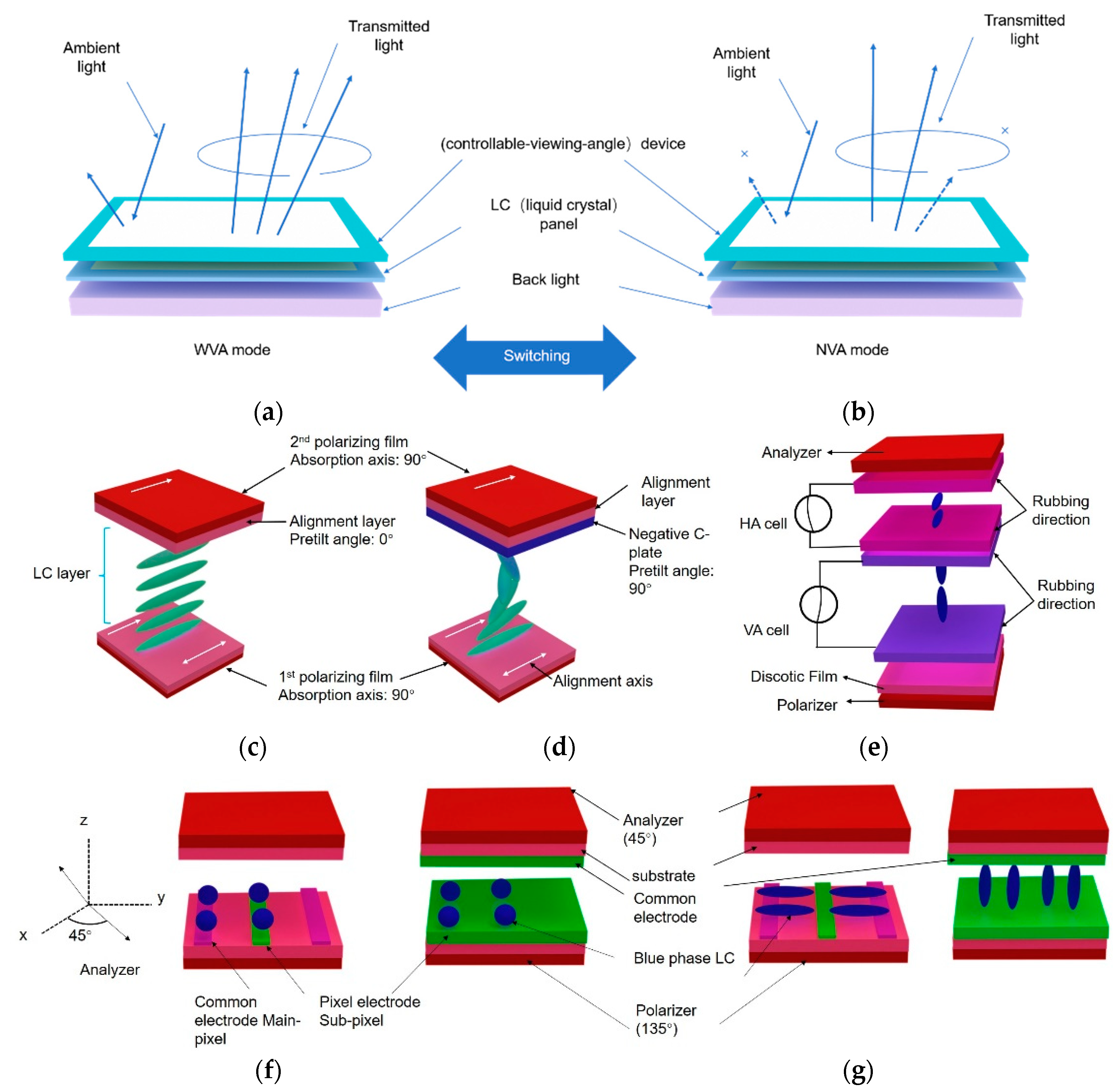
Figure 1. Schematic diagram of controllable viewing angle LCD: (a) WVA mode; (b) NVA mode. Schematic diagram of simulation models of controllable viewing angle device: (c) homogeneous aligned LC cell and (d) HAN LC cell; (e) optical cell configurations of the viewing angle device; (f) switchable LCD with an optically isotropic LC: voltage-off state and (g) voltage on state.
In the MVA or PVA devices, in the dark state, to improve the brightness uniformity in the gray levels, the addition of a compensation film is for suppressing light leakage. In the film compensation method, to compensate for the dark state, a negative C plate and positive A plate are introduced for compensating for the dark state, a WVA with the contrast ratio over 10 is extended from 30° to 80° of polar angle is achieved [7]. The double-cell display is mainly composed of a vertically aligned LC layer for displaying information, a homogeneous aligned LC layer replacing the positive A plate for viewing angle switching, and a negative C plate for compensation under crossed polarizer [7]. Without electric field, the vertically aligned LCs with negative dielectric anisotropy tilt down to make an angle of 45°, the optic axis of the homogeneous aligned LC layer with positive dielectric anisotropy is parallel to the analyzer’s transmission axis, thus light transmitting through negative C plate and double LC cells is blocked by the analyzer, additionally, light leakage can be suppressed by homogeneous aligned LC cell and negative C plate [7]. For viewing angle switching, the mid-director of the homogeneous aligned LC layer is controlled by a vertical electric field (Figure 1e) [7], the high image quality in share mode has a polar viewing angle of 30° in the horizontal direction. However, this approach for tuning viewing angle requires additional components, leading to higher thickness and higher production cost.
When there is no electric field applied, blue phase typically appears in a very narrow temperature range, with polymer or nanomaterials stabilization, the temperature range can be extended, cubic structure in a BPLC appears to be optically isotropic, if there is a strong electric field, the anisotropy is induced along the electric field direction, which is defined as Kerr effect. By dividing pixel of the LCD device filled with a BPLC into two parts: a main pixel and a sub-pixel (Figure 1f–g), while the main pixel displays the image contents that are insensitive to viewing angle, as the birefringence is induced by transversal electric field and the LC reorientation is in the same plane, the sub-pixel controls the viewing angle. The LC cell is sandwiched between crossed polarizers, when applying a voltage between two electrodes, in-plane and vertical electric fields are produced in the main pixels and sub-pixels, respectively [7][8]. Without a bias voltage, BPLC is alike optically isotropic sphere, which is presented in Figure 1f, by the application of a bias voltage, the birefringence is induced due to Kerr effect, optic axes of BPLCs are parallel and perpendicular to the substrate in the main and sub-pixels, respectively (Figure 1g) [7][8]. A WVA is realized as the main pixels are only operated, the LCDs present a good dark in all directions, while a NVA is achieved as a bias voltage is applied to the sub-pixels, light leakage controlled by the applied voltage happens in the oblique viewing direction (Figure 1g) [7][8]. For WVA mode, the viewing angle at contrast ratio of over 10 exists up to ~ 50° in all azimuthal directions, while for NVA mode, the viewing angle at contrast ratio of 10 exist along 20° in the horizontal and the vertical directions [1]. This approach exhibits some disadvantages such as lower contrast ratio or higher driving voltage and reduces transmittance more as the dark state is kept at the area of sub-pixel [9].
To decrease the volume, weight and fabrication cost of LCD, a viewing angle switchable LCD owning an interlayer support with surface microstructures that is placed between the top and bottom substrates, the original LC layer is for presenting images and the complementary LC layer is for viewing angle tunning, thus WVA and NVA can be switched between ± 70° and ± 40° [10]. A viewing angle controllable LCD using two stable states of bistable nematic LC such as splay and 180°-twist at π cell with three-terminal electrodes, WVA is shown at splay state with interdigitated electrodes at the IPS or FFS modes, NVA is presented at the twisted state with vertical electrode [11].
2. Polymer Dispersed LCs (PDLCs) Devices
Utilizing 3M light-control film and PDLC film together to create switchable anti-peeping film, PDLC is a voltage-controlled LC film that can switch between transparent and scattering (Figure 2a), light scattering intensity of PDLC film is dependent on electric field, switchable voltage between light scattering (share mode) and transparent state (privacy mode) is approximately 5.0 V [12]. As 3M light control film and PDLC film are not integrated, a control method for light distribution patterns of PDLCs is established by controlling an internal polymer structure formed by irradiating unidirectional diffused UV light in isotropic phase (Figure 2b) [13]. To investigate the effect of micro-louver size on the viewing angle controllable ability, four micro-louver structures with the same thickness are fabricated by utilizing thiol-ene photopolymerization (40-40 μm, 40-60 μm, 60-40 μm and 60-60 μm) (Figure 2c–f), four controllable anti-peeping devices can realize WVA and NVA modes at 0 and 8 V [14]. However, external switchable anti-peeping films need to be installed on the screen, to solve this problem, the LCD containing the switchable anti-peeping film is fabricated based on PDLC, the propagation direction of the light passing the 3M light control film can be tuned by the PDLC film, the NVA mode is presented without electric field and WVA mode is shown in the application of electric field (24 V) [15].
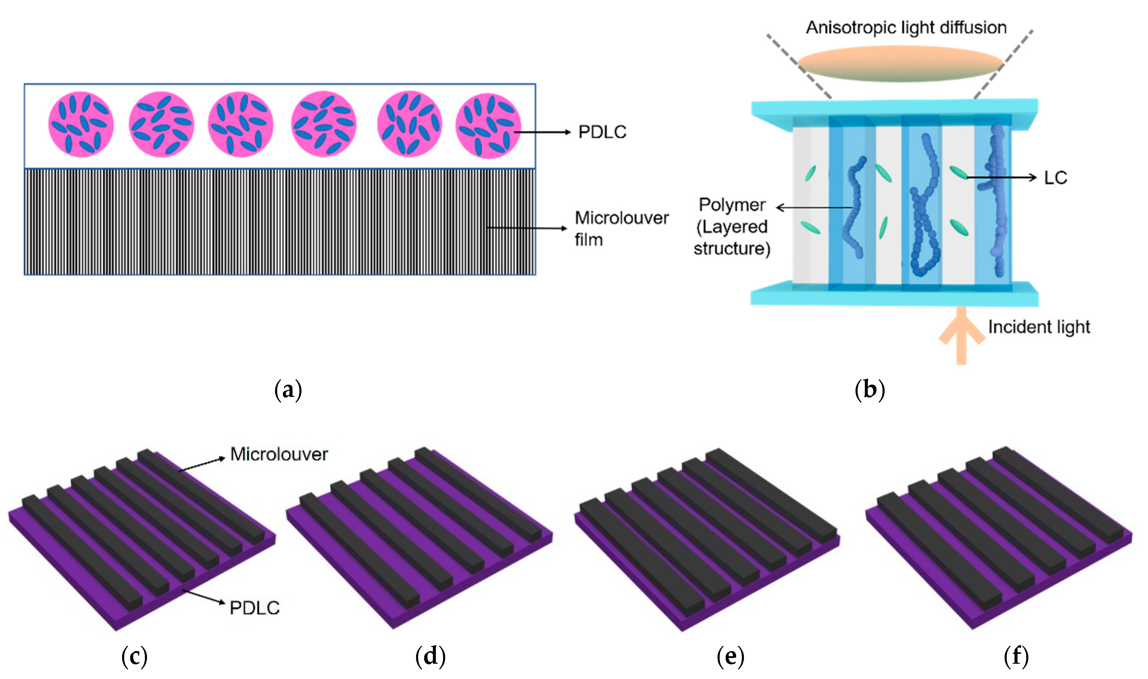
Figure 2. (a) Configuration structure and schematic mechanism of switchable anti-peeping film consists of 3M light control film and PDLC film; (b) schematic representation of PDLC having layered distribution of polymer network structure; (c–f) four microlouver structures with the same thickness, (c), 40–40 μm, (d), 40–60 μm, (e), 60–40 μm, (f), 60–60 μm, the first number represents the width of micro-stripe and the second number represents the space between two microstripes.
3. PSLC/PNLC Devices
The structure of the viewing angle-tunable LCD is depicted in Figure 3a, it consists of two cells: an ultra-super twisted (UST) cell, which is situated between the upper polarizer and the TN-TFT cell, and a PNLC cell, which is situated between the lower polarizer and the backlight. When the electric field is absent, the PNLC cell acts as a negative retarder, causing viewing angle to be wider than a conventional TN-cell [16]. Polymer stabilized BP (PSBP) LCD becomes more and more attractive due to no alignment, the simple fabrication process and fast response time, a PSBP LCD with double-size IPS electrode structure is proposed, which shows transflective characteristics because the bottom electrodes are made by aluminum material. With the application of a bias voltage on the top electrodes, a good viewing angle controllable display is exhibited [17]. A viewing angle-controllable LCD utilizing PSBPLC and a single-panel method, without electric field, a BPLC appears to be optically isotropic, if there is a strong electric field, due to Kerr effect, the birefringence is induced along the electric field direction in the BPLC and increases with the electric field, viewing angle of the device can be controlled from 100° to 30° (Figure 3b) [18]. Researchers have developed an electrically switchable viewing angle device that fabricated by DDs doped polymer stabilized cholesteric LCs (DD-PSCLCs) [19], with the additional photo-mask in the UV irradiation process, polymer has formed in the irradiated part, as shown in Figure 3c, when applying a relative lower electric field, CLCs in the irradiated part turn to be in focal conic state, while CLCs in the non-LC-irradiated part still keep planar state, as is described in Figure 3d, if the electric field is higher, CLCs in the irradiated part change to be homeotropic state, while CLCs in the irradiated part still be in the planar state (Figure 3e).
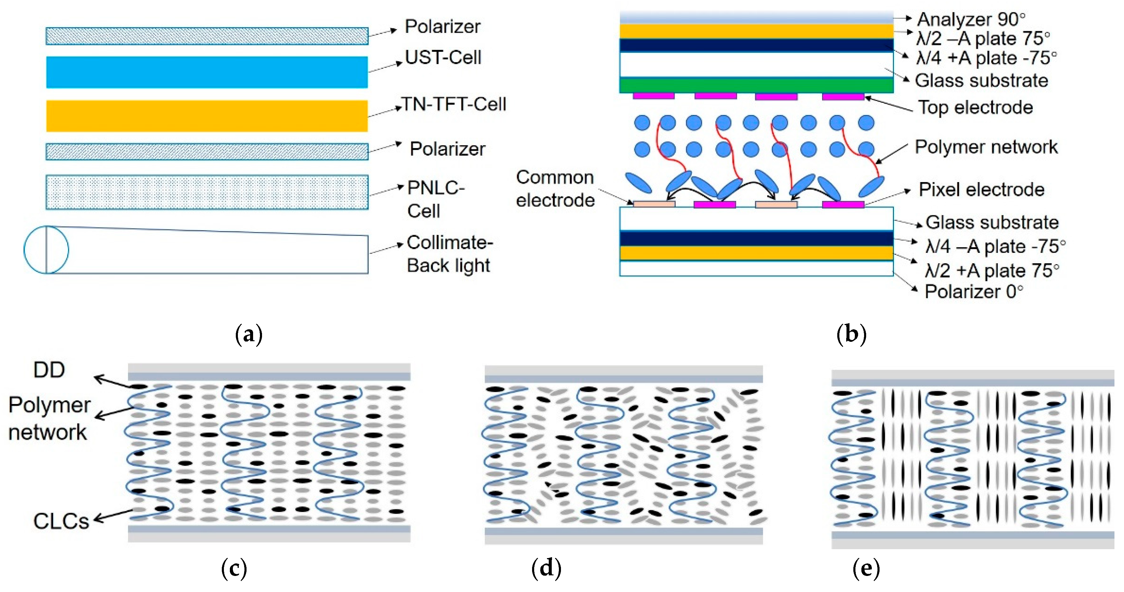
Figure 3. (a) Structure of a viewing angle controllable device; (b) Cell structure of the proposed viewing angle-controllable PSBP-LCD; (c–e) Various states of CLCs in the DD-PSCLC device under the application of electric field: (c) planar state; (b) focal conic state; (e) homeotropic state.
4. Non-LC Devices
Setting an array of optical micro-rods, consisting of electrophoretic material that composed of black particles dispersed in a transparent medium, with a rectangular parallelepiped shape, whose size is 40 μm wide, 40 μm deep and 120 μm high, while the space between each optical micro-rod is 10 μm [20][21]. As the black particles are gathered electronically to one side in the transparent resin, the cross-stripe part filled by transparent substrate transmit incident light the same as the light-transmitting portions. A viewing angle switching device based on array of optical micro-rod is demonstrated (Figure 4a), as the black particles which enables switching two states between a WVA and a NVA in one second at 20 V of applied voltage (Figure 4b). Two modes are electrically switched, (a) NVA mode and (b) WVA mode. The limited viewing angle mode is +/− 30° of the visible angle and 50% of the transmittance, and the one for the non-limited viewing mode is 58% of the transmittance by the applied voltage of 20 V. A compact light guide plate (LGP) with special designed microstructures and dual light sources is proposed (Figure 4c), of which the micro-prisms are utilized to guide the emitting rays toward normal viewing cones while a set of strip-patterned diffuser toward wide viewing cones [22][23]. By simply switching the separate light sources, quick switching between the two modes is possible. If light source 1 is on, the backlight operates in the NVA mode, and if light source 2 is on, the backlight operates in the WVA mode [24]. Figure 4d represents the viewing angle switchable backlight module that is divided into three parts, the hybrid light guide plate (HLGP) is called the light incidence surface, the first light sources provide NVA mode and the second light sources provide WVA mode, Figure 4e depicts side view of the viewing angle controllable backlight module, the HLGP is composed of main layer and sub-layer with various refractive indices, the top micro-prisms are spaced with a graded interval for controlling the uniformity degree and the bottom micro-prisms reflect the rays to the main layer [24]. Consequently, in the NVA mode, the half-luminance angle decreases 11 degrees in the horizontal direction, while in the WVA mode, the half-luminance angle increases 56 degrees in the horizontal direction [24].
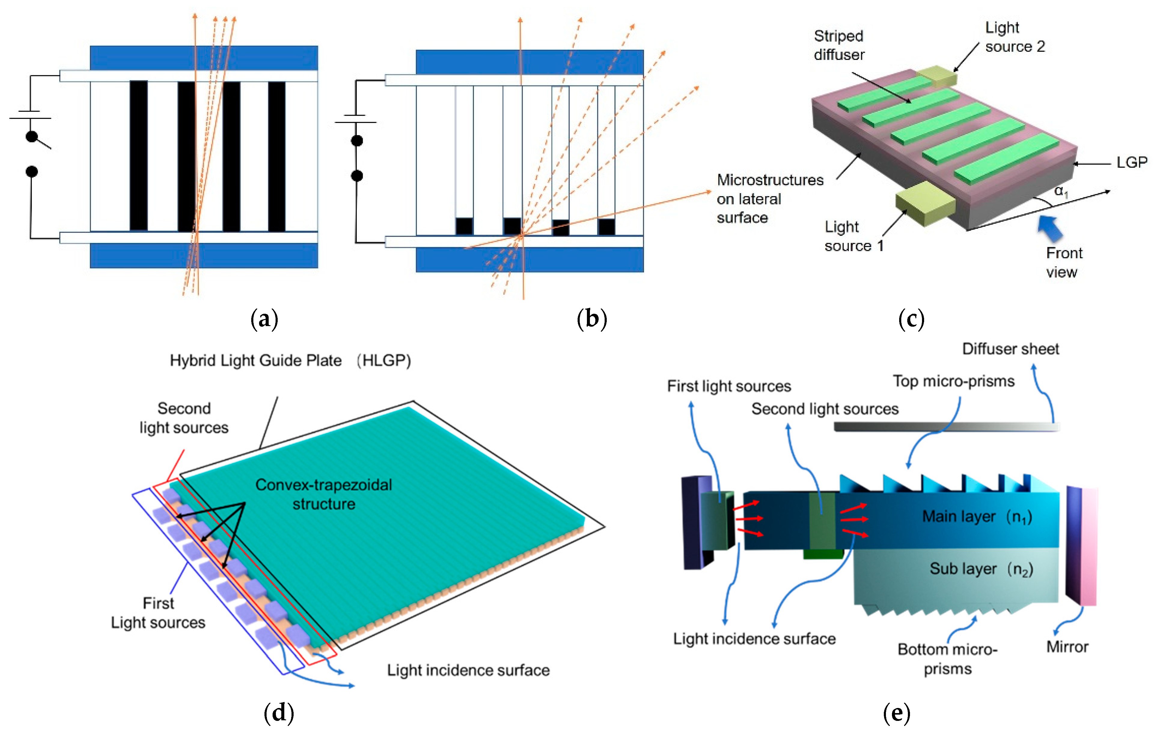
Figure 4. Illustration of concept for (a) narrow mode and (b) wide mode can be selected electronically. The narrow mode (a) is achieved as black particles are fully dispersed, and the wide mode (b) is achieved as black particles are completely gathered one side in the optically transparent medium. (c) Sketch of the backlight configuration, (d,e) optical structure of the dual backlight viewing angle switchable device: (d) tilt view; (e) side view.
References
- Kim, M.S.; Lim, Y.J.; Yoon, S.; Kang, S.W.; Lee, S.H.; Kim, M.; Wu, S.T. A controllable viewing angle LCD with an optically isotropic liquid crystal. J. Phys. D Appl. Phys. 2010, 43, 145502.
- Kim, M.S.; Lim, Y.J.; Yoon, S.; Kim, M.K.; Kumar, P.; Kang, S.W.; Kang, W.S.; Lee, G.D.; Lee, S.H. Luminance-controlled viewing angle-switchable liquid crystal display using optically isotropic liquid crystal layer. Liq. Cryst. 2011, 38, 371–376.
- Lim, Y.J.; Jeong, E.; Kim, Y.S.; Jeong, Y.H.; Jang, W.G.; Lee, S.H. Viewing angle switching in fringe-field switching liquid crystal display. Mol. Crystal. Liq. Cryst. 2008, 495, 186.
- Lim, Y.J.; Kim, J.H.; Her, J.H.; Bhattacharyya, S.S.; Park, K.H.; Lee, J.H.; Kim, B.K.; Lee, S.H. Viewing angle controllable liquid crystal display with high transmittance. Opt. Express 2010, 18, 6824–6830.
- Adachi, M. Controllable-viewing-angle display using a hybrid aligned nematic liquid-crystal cell. Jpn. J. Appl. Phys. 2008, 47, 7920–7925.
- Adachi, M.; Shimura, M. P-228L: Late-News Poster: Controllable Viewing-Angle Displays using a Hybrid Aligned Nematic Liquid Crystal Cell. SID Symp. Dig. Tech. Pap. 2006, 37, 705–708.
- Jeong, E.; Lim, Y.J.; Rhee, J.M.; Lee, S.H.; Lee, G.D.; Park, K.H.; Choi, H.C. Viewing angle switching of vertical alignment liquid crystals by controlling birefringence of homogeneously aligned liquid crystal layer. Appl. Phys. Lett. 2007, 90, 051116.
- Jeong, E.; Lim, Y.J.; Chin, M.H.; Kim, J.H.; Lee, S.H.; Ji, S.H.; Lee, G.D.; Park, K.H.; Choi, H.C.; Ahn, B.C. Viewing-angle controllable liquid crystal display using a fringe- and vertical-field driven hybrid aligned nematic liquid crystal. Appl. Phys. Lett. 2008, 92, 261102.
- Li, Y.F.; Sun, Y.B.; Zhao, Y.L.; Li, P.; Ma, H.M. A continuous viewing angle controllable blue phase liquid crystal display. J. Disp. Technol. 2014, 10, 799–803.
- Kim, Y.T.; Hong, J.H.; Cho, S.M.; Lee, S.D. Viewing angle switchable liquid crystal display with double layers separated by an interlayer support. Jpn. J. Appl. Phys. 2009, 48, 110205.
- Gwag, J.S.; Lee, Y.J.; Kim, M.E.; Kim, J.H.; Kim, J.C.; Yoon, T.H. Viewing angle control mode using nematic bistability. Opt. Express 2008, 16, 2663–2669.
- Zhou, L.; He, Z.M.; Han, C.; Zhang, L.Y.; Yang, H. Switchable anti-peeping film for liquid crystal displays from polymer dispersed liquid crystals. Liq. Cryst. 2019, 46, 718–724.
- Ishinabe, T.; Horii, Y.; Shibata, Y.; Fujikake, H. Structured PDLCs for controlling LCD viewing-angle. Dig. Tech. Pap. 2018, 49, 546–549.
- Han, C.; Zhou, L.; Ma, H.P.; Li, C.Y.; Zhang, S.F.; Cao, H.; Zhang, L.Y.; Yang, H. Fabrication of a controllable anti-peeping device with a laminated structure of microlouver and polymer dispersed liquid crystals film. Liq. Cryst. 2019, 46, 2235–2244.
- He, Z.M.; Shen, W.B.; Yu, P.; Zhao, Y.Z.; Zeng, Z.; Liang, Z.; Chen, Z.; Zhang, H.M.; Zhang, H.Q.; Miao, Z.C.; et al. Viewing-angle-switching film based on polymer dispersed liquid crystals for smart anti-peeping liquid crystal display. Liq. Cryst. 2022, 49, 59–65.
- Hisatake, Y.; Kawata, Y.; Murayama, A. Viewing angle controllable LCD using variable optical compensator and variable diffuser. SID Sym. Dig. Tech. Pap. 2005, 36, 1218–1221.
- Li, P.; Sun, Y.B.; Wang, Q.H. A transflective and viewing angle controllable blue-phase liquid crystal display. Liq. Cryst. 2013, 40, 1024–1027.
- Liu, L.W.; Cui, J.P.; Li, D.H.; Wang, Q.H. A viewing-angle-controllable blue-phase liquid-crystal display. J. SID 2012, 20, 337–340.
- Yang, H.; Zhou, L.; Ma, H.; Han, C.; Hu, W.; Zhang, L.Y. Electric Control Dimming Film for Use in Display, Has First Composite Material Area Formed by Dye Molecules and Polymer Network, Where First and Second Composite Material Areas Are Formed in Material Film Layer along Vertical Direction. Chinese Patent CN201710456245.9, 6 September 2019.
- Shiota, K.; Okamoto, M.; Tanabe, H. 76-3: Distinguished Paper: Viewing-angle-switching device based on array of optical micro-rod incorporated with electrophoretic material systems. SID Symp. Dig. Tech. Pap. 2017, 48, 1117–1120.
- Shiota, K.; Okamoto, M.; Tanabe, H. Viewing-angle-switching device based on array of optical micro-rods incorporated with electrophoretic material systems. J. Soc. Inf. Disp. 2017, 25, 76–82.
- Wang, Y.J.; Lu, J.G.; Chao, W.C. P-76: Distinguished Student Poster: Viewing Angle Switchable Display with a Compact and Directional Backlight Module. SID Symp. Dig. Tech. Pap. 2014, 45, 1270–1273.
- Wang, Y.J.; Lu, J.G.; Chao, W.C.; Shieh, H.P.D. Switchable viewing angle display with a compact directional backlight and striped diffuser. Opt. Express 2015, 23, 21443–21454.
- Chen, B.T.; Pan, J.W.; Hu, Y.W.; Tu, S.H.P. 50: Design of a novel hybrid light guide plate for viewing angle switchable backlight module. SID Symp. Dig. Tech. Pap. 2013, 44, 1181–1184.
More
Information
Subjects:
Engineering, Electrical & Electronic
Contributors
MDPI registered users' name will be linked to their SciProfiles pages. To register with us, please refer to https://encyclopedia.pub/register
:
View Times:
1.6K
Revisions:
2 times
(View History)
Update Date:
10 Oct 2022
Table of Contents


Notice
You are not a member of the advisory board for this topic. If you want to update advisory board member profile, please contact office@encyclopedia.pub.
OK
Confirm
Only members of the Encyclopedia advisory board for this topic are allowed to note entries. Would you like to become an advisory board member of the Encyclopedia?
Yes
No
${ textCharacter }/${ maxCharacter }
Submit
Cancel
Back
Comments
${ item }
|
${ item.createdUser.fullName }
${ item.createdAt }
${ item.vote }
${ item.reply }
Delete
${ reply.createdUser.fullName }
${ reply.createdAt }
${ reply.vote }
Delete
There is no reply to this comment~
${ item.replyTextCharacter }/${ item.replyMaxCharacter }
Submit
Cancel
More
No more~
There is no comment~
${ textCharacter }/${ maxCharacter }
Submit
Cancel
${ selectedItem.replyTextCharacter }/${ selectedItem.replyMaxCharacter }
Submit
Cancel
Confirm
Are you sure to Delete?
Yes
No