 +1 credit
| Version | Summary | Created by | Modification | Content Size | Created at | Operation |
|---|---|---|---|---|---|---|
| 1 | Beatrix Zheng | -- | 3267 | 2022-09-29 01:44:44 |
Video Upload Options
In electromagnetics and communications engineering, the term waveguide may refer to any linear structure that conveys electromagnetic waves between its endpoints. However, the original and most common meaning is a hollow metal pipe used to carry radio waves. This type of waveguide is used as a transmission line mostly at microwave frequencies, for such purposes as connecting microwave transmitters and receivers to their antennas, in equipment such as microwave ovens, radar sets, satellite communications, and microwave radio links. A dielectric waveguide employs a solid dielectric rod rather than a hollow pipe. An optical fibre is a dielectric guide designed to work at optical frequencies. Transmission lines such as microstrip, coplanar waveguide, stripline or coaxial cable may also be considered to be waveguides. The electromagnetic waves in a (metal-pipe) waveguide may be imagined as travelling down the guide in a zig-zag path, being repeatedly reflected between opposite walls of the guide. For the particular case of rectangular waveguide, it is possible to base an exact analysis on this view. Propagation in a dielectric waveguide may be viewed in the same way, with the waves confined to the dielectric by total internal reflection at its surface. Some structures, such as non-radiative dielectric waveguides and the Goubau line, use both metal walls and dielectric surfaces to confine the wave.
1. History

During the 1890s theorists did the first analyses of electromagnetic waves in ducts.[2] Around 1893 J. J. Thomson derived the electromagnetic modes inside a cylindrical metal cavity.[2] In 1897 Lord Rayleigh did a definitive analysis of waveguides; he solved the boundary-value problem of electromagnetic waves propagating through both conducting tubes and dielectric rods of arbitrary shape.[2][3][4][5] He showed that the waves could travel without attenuation only in specific normal modes with either the electric field (TE modes) or magnetic field (TM modes), or both, perpendicular to the direction of propagation. He also showed each mode had a cutoff frequency below which waves would not propagate. Since the cutoff wavelength for a given tube was of the same order as its width, it was clear that a hollow conducting tube could not carry radio wavelengths much larger than its diameter. In 1902 R. H. Weber observed that electromagnetic waves travel at a slower speed in tubes than in free space, and deduced the reason; that the waves travel in a "zigzag" path as they reflect from the walls.[2][4][6]
Prior to the 1920s, practical work on radio waves concentrated on the low frequency end of the radio spectrum, as these frequencies were better for long-range communication.[2] These were far below the frequencies that could propagate in even large waveguides, so there was little experimental work on waveguides during this period, although a few experiments were done. In a June 1, 1894 lecture, "The work of Hertz", before the Royal Society, Oliver Lodge demonstrated the transmission of 3 inch radio waves from a spark gap through a short cylindrical copper duct.[2][7] In his pioneering 1894-1900 research on microwaves, Jagadish Chandra Bose used short lengths of pipe to conduct the waves, so some sources credit him with inventing the waveguide.[8] However, after this, the concept of radio waves being carried by a tube or duct passed out of engineering knowledge.[2]
During the 1920s the first continuous sources of high frequency radio waves were developed: the Barkhausen-Kurz tube,[9] the first oscillator which could produce power at UHF frequencies; and the split-anode magnetron which by the 1930s had generated radio waves at up to 10 GHz.[2] These made possible the first systematic research on microwaves in the 1930s. It was discovered that transmission lines used to carry lower frequency radio waves, parallel line and coaxial cable, had excessive power losses at microwave frequencies, creating a need for a new transmission method.[2][9]
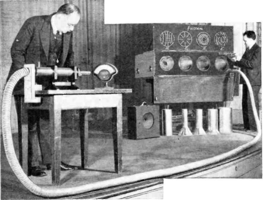
The waveguide was developed independently between 1932 and 1936 by George C. Southworth at Bell Telephone Laboratories[1] and Wilmer L. Barrow at the Massachusetts Institute of Technology, who worked without knowledge of one another.[2][4][5][9] Southworth's interest was sparked during his 1920s doctoral work in which he measured the dielectric constant of water with a radio frequency Lecher line in a long tank of water. He found that if he removed the Lecher line, the tank of water still showed resonance peaks, indicating it was acting as a dielectric waveguide.[2] At Bell Labs in 1931 he resumed work in dielectric waveguides. By March 1932 he observed waves in water-filled copper pipes. Rayleigh's previous work had been forgotten, and Sergei A. Schelkunoff, a Bell Labs mathematician, did theoretical analyses of waveguides[2][10] and rediscovered waveguide modes. In December 1933 it was realized that with a metal sheath the dielectric is superfluous and attention shifted to metal waveguides.
Barrow had become interested in high frequencies in 1930 studying under Arnold Sommerfeld in Germany.[2] At MIT beginning in 1932 he worked on high frequency antennas to generate narrow beams of radio waves to locate aircraft in fog. He invented a horn antenna and hit on the idea of using a hollow pipe as a feedline to feed radio waves to the antenna.[2] By March 1936 he had derived the propagation modes and cutoff frequency in a rectangular waveguide.[9] The source he was using had a large wavelength of 40 cm, so for his first successful waveguide experiments he used a 16-foot section of air duct, 18 inches in diameter.[2]
Barrow and Southworth became aware of each other's work a few weeks before both were scheduled to present papers on waveguides to a combined meeting of the American Physical Society and the Institute of Radio Engineers in May 1936.[2][9] They amicably worked out credit sharing and patent division arrangements.
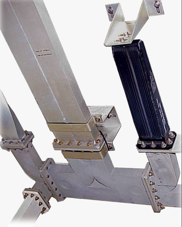
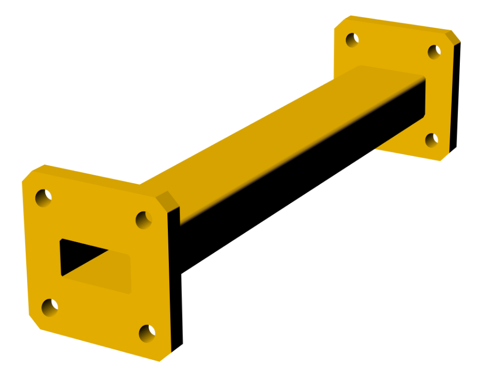
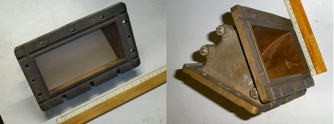
The development of centimeter radar during World War 2 and the first high power microwave tubes, the klystron (1938) and cavity magnetron (1940), resulted in the first widespread use of waveguide.[9] Standard waveguide "plumbing" components were manufactured, with flanges on the end which could be bolted together. After the war in the 1950s and 60s waveguides became common in commercial microwave systems, such as airport radar and microwave relay networks which were built to transmit telephone calls and television programs between cities.
2. Principle of Operation
Depending on the frequency, waveguides can be constructed from either conductive or dielectric materials. Generally, the lower the frequency to be passed the larger the waveguide is. For example, the natural waveguide the earth forms given by the dimensions between the conductive ionosphere and the ground as well as the circumference at the median altitude of the Earth is resonant at 7.83 Hz. This is known as Schumann resonance. On the other hand, waveguides used in extremely high frequency (EHF) communications can be less than a millimeter in width.
3. Analysis
Electromagnetic waveguides are analyzed by solving Maxwell's equations, or their reduced form, the electromagnetic wave equation, with boundary conditions determined by the properties of the materials and their interfaces. These equations have multiple solutions, or modes, which are eigenfunctions of the equation system. Each mode is characterized by a cutoff frequency below which the mode cannot exist in the guide. Waveguide propagation modes depend on the operating wavelength and polarization and the shape and size of the guide. The longitudinal mode of a waveguide is a particular standing wave pattern formed by waves confined in the cavity. The transverse modes are classified into different types:
- TE modes (transverse electric) have no electric field in the direction of propagation.
- TM modes (transverse magnetic) have no magnetic field in the direction of propagation.
- TEM modes (transverse electromagnetic) have no electric nor magnetic field in the direction of propagation.
- Hybrid modes have both electric and magnetic field components in the direction of propagation.
In hollow waveguides (single conductor), TEM waves are not possible, since Maxwell's Equations will give that the electric field must then have zero divergence and zero curl and be equal to zero at boundaries, resulting in a zero field (or, equivalently, [math]\displaystyle{ \nabla ^2 \Phi=0 }[/math] with boundary conditions guaranteeing only the trivial solution). This contrasts with two-conductor transmission lines used at lower frequencies; coaxial cable, parallel wire line and stripline, in which TEM mode is possible. Additionally, the propagating modes (i.e. TE and TM) inside the waveguide can be mathematically expressed as the superposition of TEM waves.[11]
The mode with the lowest cutoff frequency is termed the dominant mode of the guide. It is common to choose the size of the guide such that only this one mode can exist in the frequency band of operation. In rectangular and circular (hollow pipe) waveguides, the dominant modes are designated the TE1,0 mode and TE1,1 modes respectively.[12]
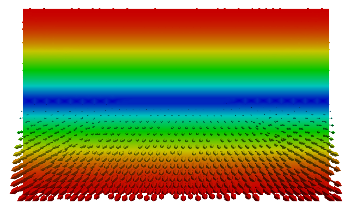
- Rectangular waveguide TE-1,0 mode
-
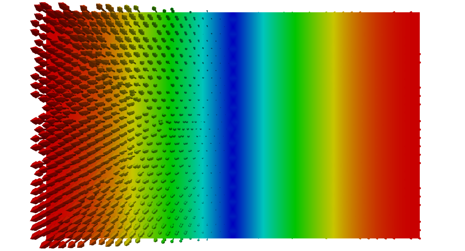
B-field, view towards cross-section. By Kyrsjo - Own work, CC BY-SA 4.0, https://commons.wikimedia.org/w/index.php?curid=52741904
-
B-field, view from the side. By Kyrsjo - Own work, CC BY-SA 4.0, https://commons.wikimedia.org/w/index.php?curid=52741907
-
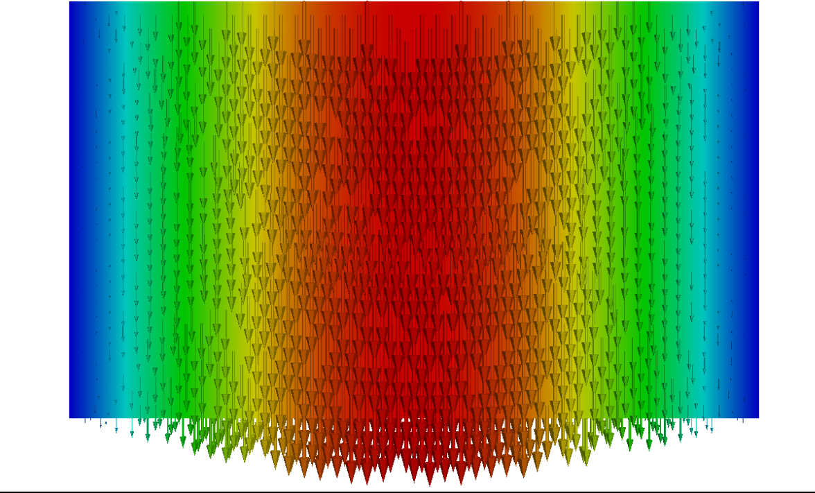
E-field, view towards cross-section. By Kyrsjo - Own work, CC BY-SA 4.0, https://commons.wikimedia.org/w/index.php?curid=52741903
.png)
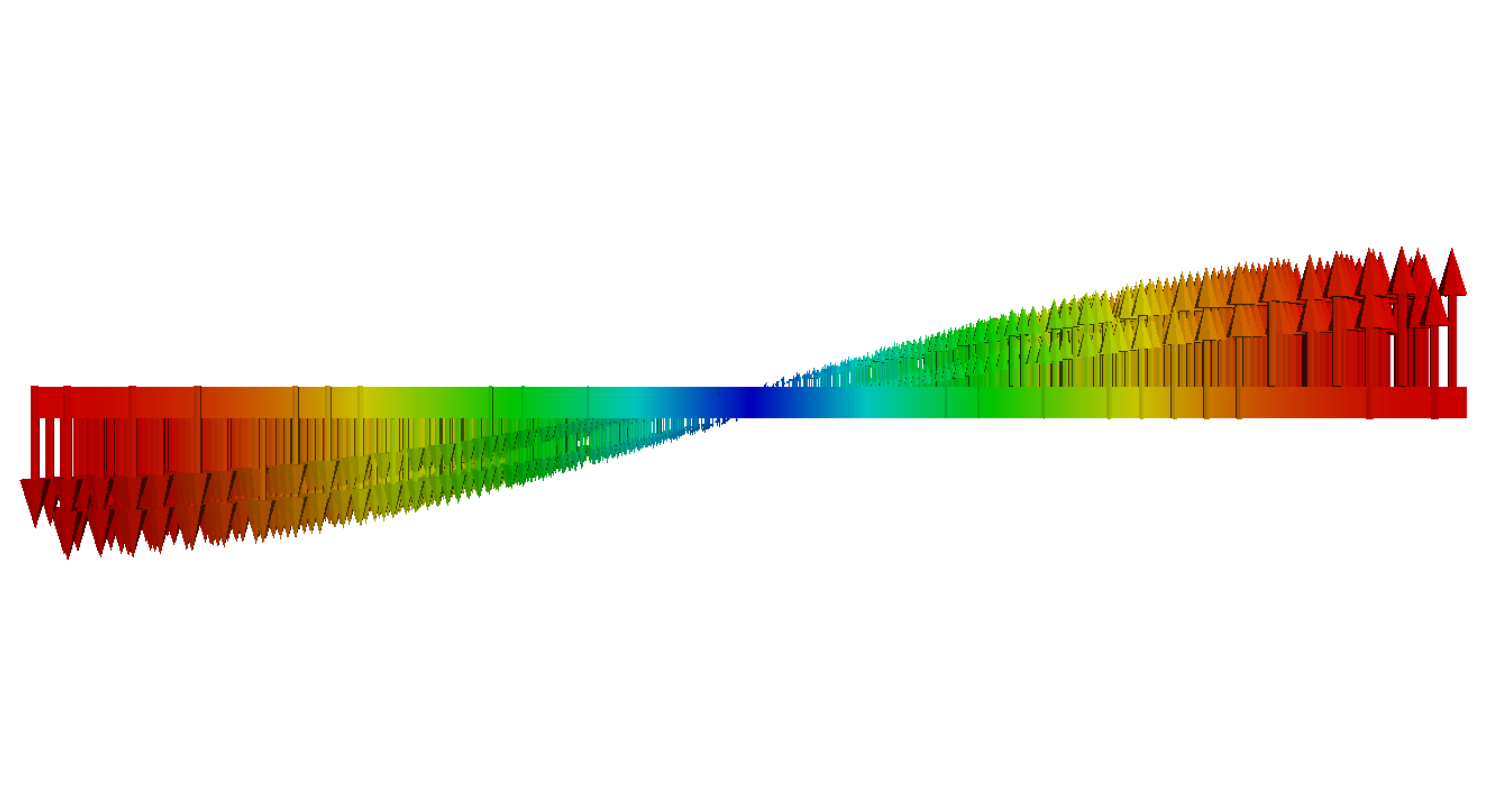
- Rectangular waveguide TE-0,1 mode
-
B-field, view towards cross-section. By Kyrsjo - Own work, CC BY-SA 4.0, https://commons.wikimedia.org/w/index.php?curid=52741439
-
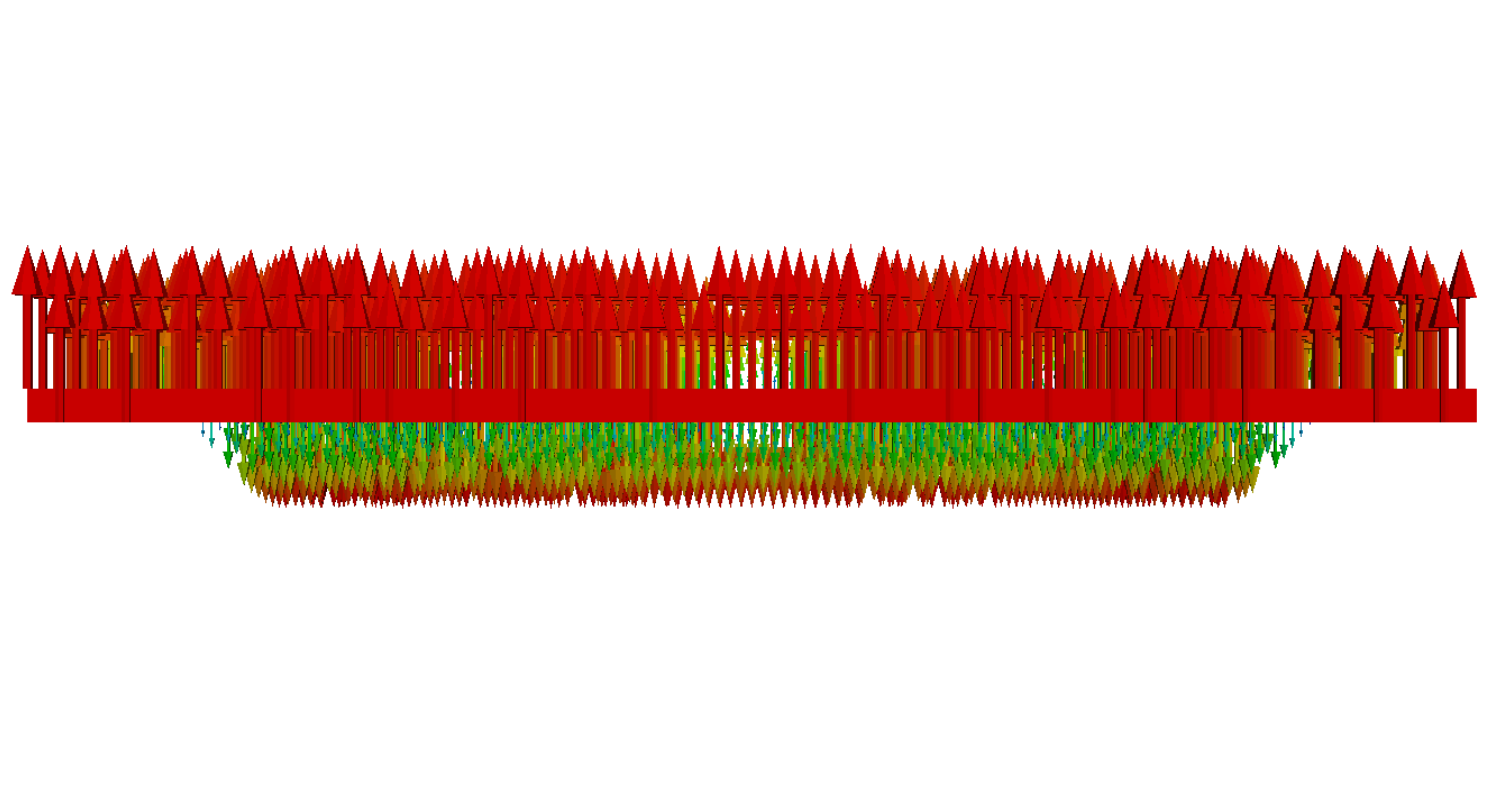
B-field, view from the side. By Kyrsjo - Own work, CC BY-SA 4.0, https://commons.wikimedia.org/w/index.php?curid=52741441
-
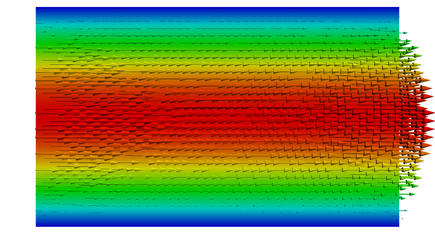
E-field, view towards cross-section. By Kyrsjo - Own work, CC BY-SA 4.0, https://commons.wikimedia.org/w/index.php?curid=52741440
.png)
-
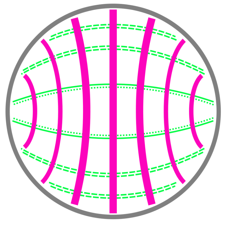
TE1,1 mode of a circular hollow metallic waveguide. By Vanessaezekowitz - SVG version by Vanessa Ezekowitz, based on this PNG, CC BY-SA 3.0, https://commons.wikimedia.org/w/index.php?curid=4520294
4. Hollow Metallic Waveguides


In the microwave region of the electromagnetic spectrum, a waveguide normally consists of a hollow metallic conductor. These waveguides can take the form of single conductors with or without a dielectric coating, e.g. the Goubau line and helical waveguides. Hollow waveguides must be one-half wavelength or more in diameter in order to support one or more transverse wave modes.
Waveguides may be filled with pressurized gas to inhibit arcing and prevent multipaction, allowing higher power transmission. Conversely, waveguides may be required to be evacuated as part of evacuated systems (e.g. electron beam systems).
A slotted waveguide is generally used for radar and other similar applications. The waveguide serves as a feed path, and each slot is a separate radiator, thus forming an antenna. This structure has the capability of generating a radiation pattern to launch an electromagnetic wave in a specific relatively narrow and controllable direction.
A closed waveguide is an electromagnetic waveguide (a) that is tubular, usually with a circular or rectangular cross section, (b) that has electrically conducting walls, (c) that may be hollow or filled with a dielectric material, (d) that can support a large number of discrete propagating modes, though only a few may be practical, (e) in which each discrete mode defines the propagation constant for that mode, (f) in which the field at any point is describable in terms of the supported modes, (g) in which there is no radiation field, and (h) in which discontinuities and bends may cause mode conversion but not radiation.
The dimensions of a hollow metallic waveguide determine which wavelengths it can support, and in which modes. Typically the waveguide is operated so that only a single mode is present. The lowest order mode possible is generally selected. Frequencies below the guide's cutoff frequency will not propagate. It is possible to operate waveguides at higher order modes, or with multiple modes present, but this is usually impractical.
Waveguides are almost exclusively made of metal and mostly rigid structures. There are certain types of "corrugated" waveguides that have the ability to flex and bend but only used where essential since they degrade propagation properties. Due to propagation of energy in mostly air or space within the waveguide, it is one of the lowest loss transmission line types and highly preferred for high frequency applications where most other types of transmission structures introduce large losses. Due to the skin effect at high frequencies, electric current along the walls penetrates typically only a few micrometers into the metal of the inner surface. Since this is where most of the resistive loss occurs, it is important that the conductivity of interior surface be kept as high as possible. For this reason, most waveguide interior surfaces are plated with copper, silver, or gold.
Voltage standing wave ratio (VSWR) measurements may be taken to ensure that a waveguide is contiguous and has no leaks or sharp bends. If such bends or holes in the waveguide surface are present, this may diminish the performance of both transmitter and receiver equipment connected at either end. Poor transmission through the waveguide may also occur as a result of moisture build up which corrodes and degrades conductivity of the inner surfaces, which is crucial for low loss propagation. For this reason, waveguides are nominally fitted with microwave windows at the outer end that will not interfere with propagation but keep the elements out. Moisture can also cause fungus build up or arcing in high power systems such as radio or radar transmitters. Moisture in waveguides can typically be prevented with silica gel, a desiccant, or slight pressurization of the waveguide cavities with dry nitrogen or argon. Desiccant silica gel canisters may be attached with screw-on nibs and higher power systems will have pressurized tanks for maintaining pressure including leakage monitors. Arcing may also occur if there is a hole, tear or bump in the conducting walls, if transmitting at high power (usually 200 watts or more). Waveguide plumbing[13] is crucial for proper waveguide performance. Voltage standing waves occur when impedance mismatches in the waveguide cause energy to reflect back in the opposite direction of propagation. In addition to limiting the effective transfer of energy, these reflections can cause higher voltages in the waveguide and damage equipment.

4.1. Waveguide in Practice
In practice, waveguides act as the equivalent of cables for super high frequency (SHF) systems. For such applications, it is desired to operate waveguides with only one mode propagating through the waveguide. With rectangular waveguides, it is possible to design the waveguide such that the frequency band over which only one mode propagates is as high as 2:1 (i.e. the ratio of the upper band edge to lower band edge is two). The relation between the waveguide dimensions and the lowest frequency is simple: if [math]\displaystyle{ \scriptstyle W }[/math] is the greater of its two dimensions, then the longest wavelength that will propagate is [math]\displaystyle{ \scriptstyle \lambda\;=\;2W }[/math] and the lowest frequency is thus [math]\displaystyle{ \scriptstyle f\;=\; c/\lambda\;=\;c/2W }[/math]
With circular waveguides, the highest possible bandwidth allowing only a single mode to propagate is only 1.3601:1.[14]
Because rectangular waveguides have a much larger bandwidth over which only a single mode can propagate, standards exist for rectangular waveguides, but not for circular waveguides. In general (but not always), standard waveguides are designed such that
- one band starts where another band ends, with another band that overlaps the two bands[15]
- the lower edge of the band is approximately 30% higher than the waveguide's cutoff frequency
- the upper edge of the band is approximately 5% lower than the cutoff frequency of the next higher order mode
- the waveguide height is half the waveguide width
The first condition is to allow for applications near band edges. The second condition limits dispersion, a phenomenon in which the velocity of propagation is a function of frequency. It also limits the loss per unit length. The third condition is to avoid evanescent-wave coupling via higher order modes. The fourth condition is that which allows a 2:1 operation bandwidth. Although it is possible to have a 2:1 operating bandwidth when the height is less than half the width, having the height exactly half the width maximizes the power that can propagate inside the waveguide before dielectric breakdown occurs.
Below is a table of standard waveguides. The waveguide name WR stands for waveguide rectangular, and the number is the inner dimension width of the waveguide in hundredths of an inch (0.01 inch = 0.254 mm) rounded to the nearest hundredth of an inch.
| Standard sizes of rectangular waveguide | ||||||||
|---|---|---|---|---|---|---|---|---|
| Waveguide name | Frequency band name | Recommended frequency band of operation (GHz) | Cutoff frequency of lowest order mode (GHz) | Cutoff frequency of next mode (GHz) | Inner dimensions of waveguide opening | |||
| EIA | RCSC * | IEC | (inch) | (mm) | ||||
| WR2300 | WG0.0 | R3 | 0.32 — 0.45 | 0.257 | 0.513 | 23.000 × 11.500 | 584.20 × 292.10 | |
| WR2100 | WG0 | R4 | 0.35 — 0.50 | 0.281 | 0.562 | 21.000 × 10.500 | 533.40 × 266.7 | |
| WR1800 | WG1 | R5 | 0.45 — 0.63 | 0.328 | 0.656 | 18.000 × 9.000 | 457.20 × 228.6 | |
| WR1500 | WG2 | R6 | 0.50 — 0.75 | 0.393 | 0.787 | 15.000 × 7.500 | 381.00 × 190.5 | |
| WR1150 | WG3 | R8 | 0.63 — 0.97 | 0.513 | 1.026 | 11.500 × 5.750 | 202.10 × 146.5 | |
| WR975 | WG4 | R9 | 0.75 — 1.15 | 0.605 | 1.211 | 9.750 × 4.875 | 247.7 × 123.8 | |
| WR770 | WG5 | R12 | 0.97 — 1.45 | 0.766 | 1.533 | 7.700 × 3.850 | 195,6 × 97.79 | |
| WR650 | WG6 | R14 | L band (part) | 1.15 — 1.72 | 0.908 | 1.816 | 6.500 × 3.250 | 165.1 × 82.55 |
| WR510 | WG7 | R18 | 1.45 — 2.20 | 1.157 | 2.314 | 5.100 × 2.550 | 129.5 × 64.77 | |
| WR430 | WG8 | R22 | 1.72 — 2.60 | 1.372 | 2.745 | 4.300 × 2.150 | 109.2 × 54.61 | |
| WR340 | WG9A | R26 | S band (part) | 2.20 — 3.30 | 1.736 | 3.471 | 3.400 × 1.700 | 86.36 × 43.18 |
| WR284 | WG10 | R32 | S band (part) | 2.60 — 3.95 | 2.078 | 4.156 | 2.840 × 1.340 † | 72.14 × 34,94 |
| WR229 | WG11A | R40 | C band (part) | 3.30 — 4.90 | 2.577 | 5.154 | 2.290 × 1.145 | 58.17 × 29.08 |
| WR187 | WG12 | R48 | C band (part) | 3.95 — 5.85 | 3.153 | 6.305 | 1.872 × 0.872 † | 47.55 × 22.2 |
| WR159 | WG13 | R58 | C band (part) | 4.90 — 7.05 | 3.712 | 7.423 | 1.590 × 0.795 | 40.38 × 20.2 |
| WR137 | WG14 | R70 | C band (part) | 5.85 — 8.20 | 4.301 | 8.603 | 1.372 × 0.622 † | 34.90 × 15.8 |
| WR112 | WG15 | R84 | — | 7.05 — 10.00 | 5.260 | 10.520 | 1.122 × 0.497 † | 28.50 × 12.6 |
| WR90 | WG16 | R100 | X band | 8.20 — 12.40 | 6.557 | 13.114 | 0.900 × 0.400 † | 22.9 × 10.2 |
| WR75 | WG17 | R120 | — | 10.00 — 15.00 | 7.869 | 15.737 | 0.750 × 0.375 | 19.1 × 9.53 |
| WR62 | WG18 | R140 | Ku band | 12.40 — 18.00 | 9.488 | 18.976 | 0.622 × 0.311 | 15.8 × 7.90 |
| WR51 | WG19 | R180 | — | 15.00 — 22.00 | 11.572 | 23.143 | 0.510 × 0.255 | 13.0 × 6.48 |
| WR42 | WG20 | R220 | K band | 18.00 — 26.50 | 14.051 | 28.102 | 0.420 × 0.170 † | 10.7 × 4.32 |
| WR34 | WG21 | R260 | — | 22.00 — 33.00 | 17.357 | 34.715 | 0.340 × 0.170 | 8.64 × 4.32 |
| WR28 | WG22 | R320 | Ka band | 26.50 — 40.00 | 21.077 | 42.154 | 0.280 × 0.140 | 7.11 × 3.56 |
| WR22 | WG23 | R400 | Q band | 33.00 — 50.00 | 26.346 | 52.692 | 0.224 × 0.112 | 5.68 × 2.84 |
| WR19 | WG24 | R500 | U band | 40.00 — 60.00 | 31.391 | 62.782 | 0.188 × 0.094 | 4.78 × 2.39 |
| WR15 | WG25 | R620 | V band | 50.00 — 75.00 | 39.875 | 79.750 | 0.148 × 0.074 | 3.76 × 1.88 |
| WR12 | WG26 | R740 | E band | 60.00 — 90.00 | 48.373 | 96.746 | 0.122 × 0.061 | 3.10 × 1.55 |
| WR10 | WG27 | R900 | W band | 75.00 — 110.00 | 59.015 | 118.030 | 0.100 × 0.050 | 2.54 × 1.27 |
| WR8 | WG28 | R1200 | F band | 90.00 — 140.00 | 73.768 | 147.536 | 0.080 × 0.040 | 2.03 × 1,02 |
| WR6, WR7, WR6,5 | WG29 | R1400 | D band | 110.00 — 170.00 | 90.791 | 181.583 | 0.0650 × 0.0325 | 1.65 × 0.826 |
| WR5 | WG30 | R1800 | 140.00 — 220.00 | 115.714 | 231.429 | 0.0510 × 0.0255 | 1.30 × 0.648 | |
| WR4 | WG31 | R2200 | 172.00 — 260.00 | 137.243 | 274.485 | 0.0430 × 0.0215 | 1.09 × 0.546 | |
| WR3 | WG32 | R2600 | 220.00 — 330.00 | 173.571 | 347.143 | 0.0340 × 0.0170 | 0.864 × 0.432 | |
- * Radio Components Standardization Committee
- † For historical reasons the outside rather than the inside dimensions of these waveguides are 2:1 (with wall thickness WG6–WG10: 0.08" (2.0 mm), WG11A–WG15: 0.064" (1.6 mm), WG16–WG17: 0.05" (1.3 mm), WG18–WG28: 0.04" (1.0 mm))[16]
For the frequencies in the table above, the main advantage of waveguides over coaxial cables is that waveguides support propagation with lower loss. For lower frequencies, the waveguide dimensions become impractically large, and for higher frequencies the dimensions become impractically small (the manufacturing tolerance becomes a significant portion of the waveguide size).
5. Dielectric Waveguides
Dielectric rod and slab waveguides are used to conduct radio waves, mostly at millimeter wave frequencies and above.[17][18] These confine the radio waves by total internal reflection from the step in refractive index due to the change in dielectric constant at the material surface.[19] At millimeter wave frequencies and above, metal is not a good conductor, so metal waveguides can have increasing attenuation. At these wavelengths dielectric waveguides can have lower losses than metal waveguides. Optical fiber is a form of dielectric waveguide used at optical wavelengths.
One difference between dielectric and metal waveguides is that at a metal surface the electromagnetic waves are tightly confined; at high frequencies the electric and magnetic fields penetrate a very short distance into the metal. In contrast, the surface of the dielectric waveguide is an interface between two dielectrics, so the fields of the wave penetrate outside the dielectric in the form of an evanescent (non-propagating) wave.[19]
References
- Southworth, G. C. (August 1936). "Electric Wave Guides". Short Wave Craft 7 (1): 198, 233. http://www.americanradiohistory.com/Archive-Short-Wave-Television/30s/SW-TV-1936-08.pdf. Retrieved March 27, 2015.
- Packard, Karle S. (September 1984). "The Origin of Waveguides: A Case of Multiple Rediscovery". IEEE Trans. On Microwave Theory and Techniques MTT-32 (9): 961–969. doi:10.1109/tmtt.1984.1132809. Bibcode: 1984ITMTT..32..961P. http://www.ieeeghn.org/wiki/images/8/86/MTT_Waveguide_History.pdf. Retrieved March 24, 2015.
- Strutt, William (Lord Rayleigh) (February 1897). "On the passage of electric waves through tubes, or the vibrations of dielectric cylinders". Philosophical Magazine 43 (261): 125–132. doi:10.1080/14786449708620969. https://dx.doi.org/10.1080%2F14786449708620969
- Kizer, George (2013). Digital Microwave Communication: Engineering Point-to-Point Microwave Systems. John Wiley and Sons. pp. 7. ISBN 978-1118636800. https://books.google.com/books?id=JVhGmjQ8TyoC&printsec=frontcover&dq=southworth+bose+lodge+waveguide.
- Lee, Thomas H. (2004). Planar Microwave Engineering: A Practical Guide to Theory, Measurement, and Circuits, Vol. 1. Cambridge University Press. pp. 18, 118. ISBN 978-0521835268. https://books.google.com/books?id=uoj3IWFxbVYC&pg=PA18.
- Weber, R. H. (1902). "Elektromagnetische Schwingungen in Metallrohren". Annalen der Physik 8 (4): 721–751. doi:10.1002/andp.19023130802. Bibcode: 1902AnP...313..721W. https://dx.doi.org/10.1002%2Fandp.19023130802
- Lodge, Oliver (June 1, 1984). "The Work of Hertz". Proc. Of the Royal Institution 14 (88): 331–332. https://books.google.com/books?id=JNINAQAAIAAJ&pg=PA331&dq=%22hollow+cylinder%22#v=onepage&q=%22hollow%20cylinder%22&f=false. Retrieved April 11, 2015.
- Emerson, Darrel T. (1998). Jagadish Chandra Bose: Millimeter-wave research in the 19th century. US National Radio Astronomy Observatory. https://www.cv.nrao.edu/~demerson/bose/emerson_delhi.pdf. Retrieved April 11, 2015.
- Brown, Louis (1999). Technical and Military Imperatives: A Radar History of World War 2. CRC Press. pp. 146–148. ISBN 978-1420050660. https://books.google.com/books?id=uYgsr3exvS4C&pg=PA147&lpg=PA147&dq=barrow+southworth+waveguide.
- Schelkunoff, Sergei A. (November 1937). "Electromagnetic Waves in Conducting Tubes". Physical Review 52 (10): 1078. doi:10.1103/PhysRev.52.1078. Bibcode: 1937PhRv...52.1078S. https://dx.doi.org/10.1103%2FPhysRev.52.1078
- Chakravorty, Pragnan (2015). "Analysis of Rectangular Waveguides – An Intuitive Approach". IETE Journal of Education 55 (2): 76–80. doi:10.1080/09747338.2014.1002819. https://dx.doi.org/10.1080%2F09747338.2014.1002819
- A. Y. Modi and C. A. Balanis, "PEC-PMC Baffle Inside Circular Cross Section Waveguide for Reduction of Cut-Off Frequency," in IEEE Microwave and Wireless Components Letters, vol. 26, no. 3, pp. 171-173, March 2016. doi:10.1109/LMWC.2016.2524529 https://doi.org/10.1109%2FLMWC.2016.2524529
- "Module 12: Waveguide Plumbing". Plasma and Beam Physics Research Facility, Dept. of Physics and Materials Science, Chiang Mai University, Thailand. 2012. http://www.fnrf.science.cmu.ac.th/waveguide/Waveguide%20theory%2012.html. Retrieved September 21, 2015.
- For bandwidths lower than 2:1 it is more common to express them as a percentage of the center frequency, which in the case of 1.360:1 is 26.55 %. For reference, a 2:1 bandwidth corresponds to a 66.67 % bandwidth. The reason for expressing bandwidths as a ratio of upper to lower band edges for bandwidths greater than 66.67 % is that in the limiting case that the lower edge goes to zero (or the upper edge goes to infinity), the bandwidth approaches 200 %, which means that the entire range of 3:1 to infinity:1 map into the range 100 % to 200 %.
- Harvey, A. F. (July 1955). "Standard waveguides and couplings for microwave equipment". Proceedings of the IEE - Part B: Radio and Electronic Engineering 102 (4): 493–499. doi:10.1049/pi-b-1.1955.0095. https://dx.doi.org/10.1049%2Fpi-b-1.1955.0095
- Baden Fuller, A. J. (1969). Microwaves (1 ed.). Pergamon Press. ISBN 978-0-08-006616-5.
- Lioubtchenko, Dmitri; Sergei Tretyakov; Sergey Dudorov (2003). Millimeter-Wave Waveguides. Springer. pp. 149. ISBN 978-1402075315. https://books.google.com/books?id=CoihHs1Ctp4C&pg=PA149&dq=%22dielectric+waveguide.
- Shevgaonkar, R. K. (2005). Electromagnetic Waves. Tata McGraw-Hill Education. pp. 327. ISBN 978-0070591165. https://books.google.com/books?id=VRMGaHDuaFQC&pg=PA327&dq=%22dielectric+slab%22+waveguide.
- Rana, Farhan (Fall 2005). "Lecture 26: Dielectric slab waveguides". Electrical Engineering Dept. Cornell Univ.. https://courses.cit.cornell.edu/ece303/Lectures/lecture26.pdf. Retrieved June 21, 2013. p. 2-3, 10

