Your browser does not fully support modern features. Please upgrade for a smoother experience.
Submitted Successfully!
 +1 credit
Thank you for your contribution! You can also upload a video entry or images related to this topic.
For video creation, please contact our Academic Video Service.
Video Upload Options
We provide professional Academic Video Service to translate complex research into visually appealing presentations. Would you like to try it?
Cite
If you have any further questions, please contact Encyclopedia Editorial Office.
Zhang, H.; Zhang, C.; Chen, J.; Li, A. Symmetric Silicon MEMS Gyroscope Mode-Matching Technologies. Encyclopedia. Available online: https://encyclopedia.pub/entry/28184 (accessed on 08 June 2026).
Zhang H, Zhang C, Chen J, Li A. Symmetric Silicon MEMS Gyroscope Mode-Matching Technologies. Encyclopedia. Available at: https://encyclopedia.pub/entry/28184. Accessed June 08, 2026.
Zhang, Han, Chen Zhang, Jing Chen, Ang Li. "Symmetric Silicon MEMS Gyroscope Mode-Matching Technologies" Encyclopedia, https://encyclopedia.pub/entry/28184 (accessed June 08, 2026).
Zhang, H., Zhang, C., Chen, J., & Li, A. (2022, September 30). Symmetric Silicon MEMS Gyroscope Mode-Matching Technologies. In Encyclopedia. https://encyclopedia.pub/entry/28184
Zhang, Han, et al. "Symmetric Silicon MEMS Gyroscope Mode-Matching Technologies." Encyclopedia. Web. 30 September, 2022.
Copy Citation
The symmetric "micro-electromechanical systems” (MEMS) gyroscope is a typical representative of inertial navigation sensors in recent years. It is different from the traditional mechanical rotor gyroscope in that it structurally discards the high-speed rotor and other moving parts to extend the service life and significantly improve accuracy. The highest accuracy is achieved when the ideal mode-matching state is realized. Due to the processing limitation, this index cannot be achieved, and can be only explored to approach this index continuously.
symmetrical gyroscope
modal matching
structural tuning
1. Introduction
Since the beginning of "micro-electromechanical systems” (MEMS) sensors in inertial guidance in the twentieth century, numerous high-precision and high-reliability sensors have been used. Many research scholars have launched extensive exploration for error suppression and performance improvement to explore the performance of the perfect MEMS gyroscope.
In the background to the rapid development of integrated circuits and silicon processing, Muller’s research team at the University of California, Berkeley, was the first to propose the concept of “micro-electromechanical systems” (MEMS) with intelligent structures based on silicon integration processes in the range of 1 μm to 1 mm. This ultra-miniature electrostatic motor has a simple structure and high no-load speed compared to the electromagnetic motor, suitable for the electrostatic drive of microsystem, so the application of electrostatic motor has been mainly focused on MEMS sensors in many countries since.
MEMS gyroscopes used to measure the angular velocity of the carrier are the most common types of inertial sensors, and consumer gyroscopes mostly use the tuning fork structure. However, because this gyroscope is extremely sensitive to the temperature coefficient, it is not destined to become a member of the high-precision sensor family. Dual mass, hemispherical, ring, and other symmetric structures of MEMS gyroscope can make the angular rate measurement insensitive to irrelevant variables, such as ambient temperature and common mode noise, thus improving the gyroscope reliability and anti-interference, widely used in the environments of high precision and high signal-to-noise ratio signal acquisition [1][2][3][4][5]. In the current public gyroscope test data, high precision indexes are done mainly by the hemispherical gyroscopes. Due to the complex processing process, two-dimensional axisymmetric gyroscopes are cost-effective choices [5][6]. The symmetric MEMS gyroscope meets the increasing demand for position services.
2. Basic Features and Critical Parameters
Symmetric gyroscopes mainly include tuning fork vibration gyroscope, vibrating ring gyroscope (VRG) and hemispherical resonant gyroscope (HRG) [7]. They all belong to the Coriolis vibration gyroscope. This section mainly introduces the symmetrical gyroscope’s different structural materials and operating mechanisms.
2.1. Drive and Sense Method
Coriolis vibration gyroscopes have two crucial parts, the drive and sense parts. The general drive part adopts the electrostatic excitation method, and the sense part adopts the capacitive detection method [7][8][9][10][11][12].
There are three primary forms of electrostatic actuation: angular vibration, line vibration and standing wave vibration. The capacitive detection method has two primary structure forms: angular vibration and line vibration. Therefore, there are various combinations of drive-sense mode, as needed.
The tuning fork vibratory gyroscope is the ancestor of the vibratory gyroscope. After years of careful research, J. Lyman and R.E. Barnaby of the Sperry company first disclosed their discovery, the Sperry tuning fork vibratory gyro (gyrotron), in the United States in 1953. The design is the first vibratory gyroscope in the world. Since 1993, the Charles Stark Draper Laboratory (CSDL) (Cambridge, MA, USA) and Rockwell International Corp. (Milwaukee, WI, USA) researchers have been working to commercialize CSDL’s silicon tuning fork gyro in the automotive industry [13]. Tuning fork gyroscopes generally use linear and angular vibration methods.
Angular vibration was a more common drive method in the early days of symmetrical gyroscopes. In 1988, the research team in the Draper Laboratory developed an inner and outer dual-frame silicon miniature angular vibration gyroscope [14]. The outer frame is used for driving and the inner frame is used for sensitive external angular velocity input. This type of vibration generally requires a structure with two frames, an inner and an outer frame. The outer frame of the instrument, together with the two internal frames and the mass block, rotates at high frequencies and with small amplitude under electrostatic actuation.
In 1993, the Draper Laboratory’s researchers improved the dual-frame gyroscope with a line vibration drive and angular vibration sensitivity. The performance index has been dramatically improved. The adequate size is 1 mm and the drive amplitude is six μm. The Q values of the drive and sense axes are 40,000 and 5000, respectively [15][16][17]. The linear vibration drive relies mainly on the comb drive. When an AC signal is applied to the fixed pole plate of the driver, the moving pole plate is displaced. The gyroscopic effect occurs when the external angular velocity is used [18]. Compared with the angular vibration drive, the line vibration drive has the following advantages:
-
Angular vibration requires a double frame structure. This gyroscope fabrication process is more complex, while the processing of comb-driven gyroscope is relatively simple.
-
The comb driver uses the surface processing method. This method is compatible with the line integration process.
-
Due to the second point of compatibility, the integration of the gyroscope detection chip is also improved.
Therefore, line vibration is the most commonly used excitation and detection method. In 2021, Nanjing University of Science and Technology designed a decoupled bilinear vibration gyroscope. At a vibration level of 7.0 g, the vibration variation is <10°/h and the zero bias stability is close to 10°/h over the whole temperature range. This test level is only one order of magnitude away from the tactical level (1°/h) [19].
The other two symmetrical gyroscopes are the VRG and HRG. Their working principle is the same. Therefore, the excitation-detection principles of both are the same. The VRG and HRG are driven and sensed using standing wave vibrations. As a vibrating structure rotates, the standing wave also rotates due to inertial forces. The angular rotation rate is proportional to the angular rotation rate of the external carrier, and the proportion is fixed [20][21][22][23]. This phenomenon is called the “Bryan effect”.
Although the VRG and HRG work on the same principle, the advantages and disadvantages differ significantly. They have significant differences in preparation materials and processing methods. The VRG is a surface processing method and the HRG is a body processing method. The accuracy of hemispherical gyroscopes is comparable to that of laser gyroscopes, mainly used in aerospace. The United States was the first to start researching the hemispherical resonant gyroscope (HRG). In addition, Russia’s research on hemispheric gyroscopes has been very fruitful. In 1993, an HRG with a diameter of 100 mm and 50 mm was developed by the Russian Ramin Design Bureau (Saint Petersburg, Russia). The performance indexes are a random drift of 0.001~0.005°/h, a random wander of 0.005–0.01°
/√h
and a lifetime of up to 20 years [24][25]. However, hemispherical gyroscopes are smaller and simpler systems compared to optical gyroscopes.
The machining of the HRG resonator is very complex, so the ring gyroscope with surface machining was born. The VRG is divided into single-ring and multi-ring (disc). Flexible beams connect multi-ring structures and have electrodes embedded between the rings, increasing the drive and detection capacitance. In 2000, F. Ayazi and K. Najafi of the University of Michigan (Ann Arbor, MI, USA) designed a polycrystalline silicon ring gyroscope with 80 μm thickness, 1.1 mm diameter, and 20:1 aspect ratio. The gyroscope was tested to have a resolution better than 1°
/s in a 1 Hz bandwidth and this result is one of the more classic designs in the early stages of VRG development [26].
2.2. Materials
In the past, quartz crystal was the primary material for making sensors. Quartz material has an excellent piezoelectric effect and temperature stability. Importantly, even in a non-vacuum environment, quartz can achieve a high Q value, which helps to improve the sensitivity and SNR of the gyroscope. With the development of microsystem technology, researchers have higher and higher requirements for gyroscope integration.
However, quartz is hard and brittle, which is unsuitable for micromachining [27][28][29][30][31][32]. Therefore, people began to use silicon instead of quartz crystal. The Youngs modulus of silicon is directional, which will cause more significant mechanical coupling and zero drift between driving mode and vibration mode [33][34][35].
Since the 1980s, fused quartz has been utilized again. Fused quartz is isotropic and has a minimal expansion coefficient. Fused quartz has no anisotropy and has a very low expansion coefficient and impurity level. In this way, the thermoelastic loss and volume internal friction are reduced. At the same time, the quality factor of the structure is increased. In recent years, hemispherical gyroscopes with high precision and high Q value have been prepared by fused quartz [36][37]. In 2021, the research team at the National University of Defense Technology introduced a micro hemispherical resonator with teeth-like tines along the edge. The n = 2 wineglass modes operate at 4.3 kHz, achieving a quality factor of 1.18 million [38]. The same year, the research team at Wuhan University presented a high-performance piezoelectric ring resonator with an ultra-low relative frequency split. It achieves an ultra-low relative frequency split of 11.2 ppm at its resonant frequency of 456.68 kHz. The measured Q values are between 11,391 and 15,324, with an average of 13,296 [39]—two orders of magnitude difference in quality factors between VRG and HRG.
2.3. Operating Mechanism
There are two operating mechanisms of tuning fork gyroscope: open-loop detection and closed-loop detection, collectively referred to as rate mode or amplitude modulation (AM) mode. In open-loop detection, the detection displacement amplitude of gyro output is proportional to the input angular velocity and the demodulated voltage reflects the angular velocity information.
In Figure 1, Gy(s) is the transfer function of the gyroscope detection mode; K is the forward path gain; Flpf(s) is the low-pass filter transfer function in demodulation; Vrefsin(ωdt+φ0) is the modulating signal; Vopen(t) is the output signal, which can reflect the angular velocity. The open-loop control system has a simple model and high loop gain. However, the system stability is poor and few scenarios are currently applied. In the closed-loop detection (force balance detection), a force feedback detection electrode is added to the gyro detection mode. The feedback force of the closed loop counteracts the Coriolis force. Feedback force reflects the magnitude of angular velocity. It is characterized by excitation mode constant amplitude vibration, and the detection mode displacement is kept at zero. In the force balance mode, the gyroscope scale factor is independent of the forward path gain and is only related to the feedback gain. This operating mechanism dramatically improves the scale-factor stability. In addition, the response is usually linear because the detected modal motion is always near the zero position. In the various electrical tuning methods mentioned later, as described in [40][41][42][43], gyroscopes are based on a force feedback operating mechanism [44][45].
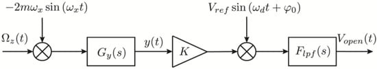
Figure 1. Schematic diagram of gyroscope open-loop detection.
In addition to the AM mode, the operating mechanism of the VRG and HRG have a whole-angle (WA) mode, also called the rate-integrating mode. The WA mode is one of the most typical applications of the Bryan effect. When there is an external angular velocity, the standing wave of the resonator and the electrode rotate with the carrier. However, the rotation of the standing wave always lags behind the course of the base by a fixed ratio. This fixed ratio is called the feed factor or Bryan factor. The carrier’s motion can be deduced by combining the standing wave rotation angle and the feed factor.
Since the WA mode directly outputs the angular information of the carrier, it can avoid the drift introduced by integrating the angular rate gyroscope, and it has the advantages of large bandwidth, high dynamics, and high linearity. However, the standing wave axis is inferred using the proportional relationship between the 0° and 45° signals. It is easier to introduce quantization errors in this process, resulting in lower measurement resolution in the WA mode. The researchers at the University of California presented a generalized electronic feedback method for compensating resonator anisodamping and anisoelasticity using the WA operation in a new way. The operation overcomes the precession angle-dependent bias error and minimum rate threshold. This method has decreased the angle-dependent bias error by 30, resulting in a minimum rate threshold of 3.5 DPS. The RIG’s output noise is also evaluated, demonstrating an ARW of 11 mdps/√Hz, similar to rate gyro operation at the same amplitude [46].
3. Mode-Matching Technology Based on Mechanical Tuning
3.1. Mode-Matching Approach with Fine-Tuning of Structural Parameters
Since the gyroscope can be viewed as a classical second-order system, there is a relationship between its modal frequency and equivalent mass (Equation (7)). One of the means of mechanical tuning is to change the mass and stiffness of the symmetric gyroscope and further change the mode frequency, such as mass deposition, resonator coating, laser etching, etc. In 2005, researchers at the Georgia Institute of Technology (Atlanta, GA, USA) proposed a method for fine-tuning the modal frequency of MEMS resonators by adding gold-plated single crystal silicon to the upper surface of the resonator. The resonator’s increased mass where the silicon is deposited changes the equivalent stiffness and modal frequency. This tuning method achieves a high level of sensitivity but requires precise knowledge of the resonator mode nodes [47].
The above method is a purely mechanical tuning, and the controllability needs improvement. In 2009, the researchers at UCLA combined electromagnetic driving and capacitive sensing to form a control system. A disk-shaped NdFeB magnet is placed on a resonator to simulate reversible mass perturbations. The electromagnetic actuator generates a varying current through its solenoid valve to apply a radial force to the resonator. The capacitor is a brass disk parallel to the resonator’s outermost edge—the capacitance between the resonator and the brass disk changes as the resonator vibrates. Test data showed that the modal frequency changes at about 0.2 Hz per unit mass [48].
Due to the presence of electromagnetic devices, the object under test must be considered less susceptible to interference from the electromagnetic environment. Care must be taken to also isolate the high-frequency current from which the gyroscope drives the modal. The research team proposed improvements to the above method. They studied the tuning scheme with mass deposition in the outer layer of the gyroscope spokes.
In 2021, the National University of Defense Technology (Changsha, China) researchers reported a novel ring MEMS resonator and a novel method of mechanical frequency tuning. The most prominent characteristic of the resonator is that 16 raised mass blocks are increased uniformly in the circumferential positions of the ring. However, the stiffness of the resonator is almost unchanged, which shows that the scheme can realize the decoupling of mass and stiffness. The frequency difference has a linear relationship with the changed quality [49].
The above “mass addition” tuning method increases the equivalent mass of the gyroscope, resulting in increased system power consumption. In 2001, the researchers at the University of Nottingham (Nottingham, UK) introduced the concept of “equivalent defect mass” for the first time, which was also the first time that the idea of “structural mass subtraction” was used. According to the Rayleigh–Ritz method, the researchers analyzed the effect of resonator mass imbalance on the modal error. They proposed the process of modal trimming by eliminating these mass imbalance errors at specific locations of the resonator. Still, this method only applies to trimming the edges of single and two pairs of oscillators [50].
Gallacher’s research team at Newcastle University (Newcastle, UK) investigated the use of laser ablation to achieve modal frequency trimming of non-ideal ring structures in 2003. Researchers theoretically analyzed how the ablation results change the intrinsic frequencies of both in-plane and out-of-plane deflections, including the effect of mechanical stiffness and mass reduction due to ablation on the frequency shift [51]. The team performed an experimental verification.
3.2. New Materials or Structures for Mode-Matching Approach
The other mechanical tuning is to retain the energy conversion working principle of the symmetric gyroscope but completely abandon the past’s more common gyroscope processing structure and materials. The design changes are more thorough than the previous one.
Silicon and quartz are the primary preparation material. However, there are also research teams using new materials and structures to reduce the disadvantages of traditional processing methods affecting the accuracy of the gyroscope in improving sensor performance. When considering the use of new materials and processes, researchers should not limit ourselves to the purpose of accuracy improvement but also consider the cost, power consumption, and safety compared with the original solution. Therefore, the index test is also multifaceted.
This tuning approach was gradually developed in the early 21st century, with a relatively short research history. In 2001, a research team at the University of California, Berkeley, integrated a mechanical beam structure composed of a thermistor into a comb micro-resonator for frequency tuning based on the local thermal stress effect. After heating, a resonator with a center frequency around 31 kHz was measured to change to 6.5%. Subsequently, hundreds of millions of frequency tunings were performed, and no visible material breakage was found on the resonator [40]. According to the experimental results, the research team established an electro-thermal dynamic model to improve the theoretical study.
While this tuning method had outstanding reliability, power consumption, and sensitivity advantages, replacing the mechanical beam material with a thermistor would increase the temperature drift of the system. This result reduced the system temperature stability, and it was not suitable as a measurement and control device for variable temperature environments.
In 2017, a new honeycomb disc resonant gyro was developed by researchers at the National University of Defense Technology, whose topology consists of several interlaced hexagonal cells. The design had the advantages of high space utilization and excellent mechanical properties. Test results showed that the inherent frequency of the resonator was about 17,140 Hz, and the frequency cracking could be reduced to less than 0.1 Hz after electrostatic tuning [52].
In 2019, a new spider-web type disc resonant gyroscope (CDRG) was designed by the research team at the Soochow University. Its linear structure reduced the manufacturing defects dramatically compared with the DRG (RDRG). The performance tests of CDRG and RDRG were compared, and the results showed that the minimum frequency split of CDRG was 10.8 times smaller than the relative frequency split of RDRG built side-by-side on the same wafer. The maximum vibration displacement, scale factor, angular random wander, and bias instability were improved by 62.8%, 112%, 700%, and 314%, respectively [53].
Gyroscopes are also used in car navigation systems. To ensure impact resistance and high precision, Murata Manufacturing (Kyoto, Japan) and Kanazawa Murata Manufacturing (Hakusan, Japan) reported a precise MEMS gyroscope with a ladder structure in 2007. The fabricated gyroscope sensor module showed low acceleration sensitivity and stability [54].
The Q value of the above design was too low, reducing the accuracy and not meeting the autonomous driving specification. After that, the Department of Device R&D co-operated with the University of Michigan, composing a ladder structure. Capable of suppressing energy dissipation, the ladder structure allowed the Q-factors of drive and sense modes to reach 120,000, an excellent value as a Si-tuning fork gyroscope. The mode-matched high Q-factor ladder gyroscope showed a random angle walk (ARW) of 0.020°/√h and a bias instability (BI) of 0.20°/h [55].
The tuning process of the ring and hemisphere gyroscopes requires two steps to complete. The first step must be to decouple the two operating modes, and then the negative stiffness effect is used to change the modal frequencies until they match. Therefore, mechanical tuning can be done by employing some materials with less modal coupling or design. The researchers at Politecnico di Torino (Torino, Italy) presented a new, structurally and thermally stable design of a resonant mode-matched electrostatic z-axis MEMS gyroscope. The novelty of the proposed MEMS gyroscope design lay in the implementation of two separate masses for the drive and sense axis, using a unique mechanical spring configuration that allowed minimizing the cross-axis coupling between the drive and sense modes [56].
Considering the mode mismatch caused by temperature change, a comb-driven electrostatic tuning electrode is added to the gyroscope.
4. Emerging Algorithms Incorporated Modal Matching Technology
Various emerging algorithms are widely applied to control systems with the rise of cross-research between artificial intelligence and other disciplines.
In 2015, the research team at Peking University (Peking, China) designed a real-time mode-matching method for gyroscopes based on fuzzy control and neural network algorithms. Given the nonlinearity of the controlled object, a two-dimensional fuzzy controller is used to regulate the tuning voltage. A combined neural network algorithm is used for temperature error compensation. Since the driving frequency changes with the ambient temperature, it can be measured in the driving closed loop. Therefore, the modal frequency can be regarded as a feedback variable, and the tuning voltage can be changed to achieve modal matching control.
The three-layer BP (back propagation) neural network algorithm is used for control. The input, hidden, and output layers are M, q and L neurons. At the same time, the tansig function and pureline function are used as transfer functions of the hidden layer and output layer, respectively. The steepest descent method is used in the research process to adjust the weight matrix, ωij, and ωki to minimize the training error. Then, the neural network controller can be used to predict according to the input. The mode-matching process can be achieved in less than 10 s.
The phase margin, gain margin, and sensitivity margin calculated from the experimental data reach the theoretical values. The system has sufficient stability and robustness in the temperature range of −40~80 °C. In addition, the gyroscope has a maximum bandwidth of 85 Hz and a bias instability of 5°/h under closed-loop control [57].
Later, the researchers at Hohai University (Nanjing, China) also used a fuzzy neural network algorithm to realize the stability control of the gyroscope. They innovatively proposed an adaptive fractal sliding mode control (SMC) scheme based on approximation. The scheme adopts a double loop recurrent fuzzy neural network (DLRFNN) to approximate the system uncertainty and disturbance. The simulation data shows that the model performs better in high precision and fast response [58][59][60].
References
- Li, X.; Wang, W.; Wang, S.; Peng, Y.; Jin, X. Status and development trend of MEMS inertial sensors. Meas. Technol. 2019, 39, 7.
- Challoner, A.D.; Ge, H.; Liu, J. Boeing Disc Resonator Gyroscope. In Proceedings of the 2014 IEEE/ION Position, Location and Navigation Symposium-PLANS 2014, Monterey, CA, USA, 5–8 May 2014.
- Yi, J.; Jiang, N.; Zhuang, S.; Guo, S.; Zhang, J. Status and development of MEMS solid-state fluctuating gyro resonators. Micro Nanoelectron. 2018, 55, 738–745.
- Chen, S.; Zhang, S.; Mu, X.; Chen, Y. A brief review of the development status of MEMS gyro technology at home and abroad. Sens. World 2016, 22, 19–23.
- Xia, G. Study on the Performance Stability of Silicon Micro Gyroscope Based on Digital Technology; Southeast University: Nanjing, China, 2011.
- Quan, H.; Yang, S.; Chen, X.; Wang, H. Development and Application of high-end MEMS solid-state fluctuation gyro. Navig. Control 2017, 16, 74–82.
- Yazdi, N.; Ayazi, F.; Najafi, K. Micromachined inertial sensors. Proc. IEEE 2002, 86, 1640–1659.
- Helisto, P.; Seppa, H. Analysis of international comparisons with the minimum variance method. IEEE Trans. Instrum. Meas. 2003, 52, 495–499.
- Burrough, E.; Lee, A. In-flight Characterization of Cassini Inertial Reference Units. In Proceedings of the AIAA Guidance, Navigation and Control Conference and Exhibit, Hilton Head Island, SC, USA, 20 August 2007.
- Tang, W.C.; Lim, M.G.; Howe, R.T. Electrostatically balance comb drive for controlled levitation. In Proceedings of the Solid-State Sensor and Actuator Workshop, 1990, 4th Technical Digest, Hilton Head Island, SC, USA, 4 June 1990.
- Tang, W.C.; Nguyen, T.; Howe, R.T. Laterally Driven Polysilicon Resonant Microstructures. Sens. Actuators 1989, 20, 25–32.
- Loveday, P.; Rogers, C. The influence of control system design on the performance of vibratory gyroscopes. J. Sound Vib. 2002, 255, 417–432.
- Li, X.; Yuan, J. The development status of micromechanical gyro. Adv. Mech. 2003, 33, 13.
- Greiff, P.; Boxenhorn, B.; King, T.; Niles, L. Silicon monolithic micromechanical gyroscope. In Proceedings of the International Conference on Solid-state Sensors & Actuators, Stockholm, Sweden, 6 August 2002.
- Lang, W. Reflexions on the future of microsystems. Sens. Actuators A Phys. 1999, 72, 1–15.
- Elwell, J.M. Micromechanical Inertial Swors for Commercial and Military Applications. In Proceedings of the 50th Annual Meeting of The Institute of Navigation, Washington, DC, USA, 11–13 May 1994.
- Barbour, N.; Connelly, J.; Gilmore, J.; Greiff. Micromechanical silicon instrument and systems development at Draper Laboratory. In Proceedings of the Guidance, Navigation, and Control Conference, San Diego, CA, USA, 29 July 1996.
- Wang, Z. Research on Circuit and Testing Technology of Two-Degree-of-Freedom Silicon Micro-Angle Vibrating Gyroscope; Southeast University: Nanjing, China, 2003.
- Qiu, A.; Shi, Q.; Zhao, Y.; Xia, G. Structure of Decoupling Dual-Mass Silicon Micromechanical Vibratory Gyroscope. CN Patent 202110014421X, 25 May 2021.
- Ayazi, F. A High Aspect-Ratio High-Performance Polysilicon Vibrating Ring Gyroscope; University of Michigan: Ann Arbor, MI, USA, 2000.
- Jia, Z.; Fu, L.; Ren, J. Development trend of hemispherical resonant gyro technology. Navig. Control 2018, 17, 88–92.
- Delhaye, F. HRG by SAFRAN: The game-changing technology. In Proceedings of the IEEE International Symposium on Inertial Sensors & Systems, Lake Como, Italy, 26–28 March 2018; pp. 1–4.
- Rozelle, D.M. The Hemispherical Resonator Gyro: From Wineglass to the Planets. Adv. Astronaut. Sci. 2009, 134, 1157–1178.
- Ahamed, M.J.; Senkal, D.; Shkel, A.M. Effect of annealing on the mechanical quality factor of fused quartz hemispherical resonator. In Proceedings of the International Symposium on Inertial Sensors & Systems, Laguna Beach, CA, USA, 25 February 2014; pp. 1–4.
- Darvishian, A.; Shiari, B.; Cho, J.Y.; Nagourney, T.; Najafi, K. Anchor Loss in Hemispherical Shell Resonators. J. Microelectromech. Syst. 2017, 26, 51–66.
- Ayazi, F.; Najafi, K. A HARPSS polysilicon vibrating ring gyroscope. J. Microelectromech. Syst. 2001, 10, 169–179.
- Matthews, A.; Rybak, F.J. Comparison of Hemispherical Resonator Gyro and Optical Gyro. IEEE AES Mag. 1992, 7, 40–45.
- Matthews, A.; Farmer, R. Application of the HRG to Strategic Missions. In Proceedings of the Annual Meeting-Institute of Navigation, Cambridge, MA, USA, 21–23 June 1993; pp. 551–558.
- Ragan, R.R.; Lynch, D.D. Inertial Technology for The Future, PartX: Hemispherical resonator gyro. IEEE Trans. Aerosp. Electron. Syst. 1984, AES-20, 432.
- Soderkvist, J. Design of a Solid-State Gyroscopic Sensor Made of Quartz. Sens. Actuators 1990, 21, 293–296.
- A Quartz Rotational Rate Sensor. Available online: www.systron.com (accessed on 31 July 2022).
- Burdess, J.S.; Wren, T. The Theory of a Piezoelectric Disc Gyroscope. IEEE Trans. Aerosp. Electron. Syst. 1986, 22, 410–418.
- Clark, W.A.; Horowitz, R.; Howe, R.T. Surface Micromachined Z-Axis Vibratory Rate Gyroscope. In Proceedings of the 1996 Solid-State, Actuators, and Microsystems Workshop, Hilton Head Island, SC, USA, 3–6 June 1996.
- Juneau, T.; Pisano, A.P. In Proceedings of the Micromachined Dual Input Axis Angular Rate Sensor, Solid-State Sensors, Actuators, and Microsystems Workshop, Hilton Head Island, SC, USA, 2–6 June 1996.
- Lee, K.B.; Yoon, J.B.; Kang, M.S.; Cho, Y.H.; Youn, S.K.; Kim, C.K. A Surface-micromachined Tunable Microgyroscope. In Proceedings of the IEEE Conference on Emerging Technologies & Factory Automation, Efta, Kauai, HI, USA, 18–21 November 1996.
- Efimovskaya, D.; Wang, Y.; Lin, W.; Shkel, A.M. On ordering of fundamental wineglass modes in toroidal ring gyroscope. In 2016 IEEE SENSORS; IEEE: New York, NY, USA, 2016; pp. 1–3.
- Johari, H.; Ayazi, F. High-frequency capacitive disk gyroscopes in (100) and (111) silicon. In Proceedings of the 2007 IEEE 20th International Conference on Micro Electro Mechanical Systems, MEMS, Hyogo, Japan, 21–25 January 2007; pp. 47–50.
- Shi, Y.; Xi, X.; Li, B.; Chen, Y.; Wu, Y.; Xiao, D.; Wu, X.; Lu, K. Micro Hemispherical Resonator Gyroscope with Teeth-Like Tines. IEEE Sens. J. 2021, 21, 13098–13106.
- Yang, S.; Wu, Z.; Jia, W.; Wu, G. Ultra-Low Relative Frequency Split Piezoelectric Ring Resonator Designed for High-Performance Mode-Matching Gyroscope. J. Microelectromech. Syst. 2022, 31, 6–8.
- Remtema, T.; Lin, L. Active frequency tuning for microresonators by localized thermal stressing effects. Sens. Actuators A Phys. 2001, 91, 326–332.
- Antonello, R.; Oboe, R.; Prandi, L.; Biganzoli, F. Automatic mode matching in MEMS vibrating gyroscopes using extremum-seeking control. IEEE Trans. Ind. Electron. 2009, 56, 3880–3891.
- Sonmezoglu, S.; Alper, S.E.; Akin, T. An automatically mode-matched MEMS gyroscope with wide and tunable bandwidth. J. Microelectromech. Syst. 2014, 23, 284–297.
- Jia, J.; Ding, X.; Gao, Y.; Li, H. Automatic Frequency tuning technology fordual-mass MEMS gyroscope based on a quadrature modulation signal. Micromachines 2018, 9, 511.
- Yang, C.; Li, H.; Xu, L.; Zhu, K. Automatic mode matching technology of silicon micro gyroscope based on low frequency modulation excitation. Chin. J. Inert. Technol. 2016, 24, 610–619.
- Keymeulen, D.; Peay, C.; Foor, D.; Trung, T.; Bakhshi, A.; Withington, P.; Yee, K.; Terrile, R. Control of MEMS Disc Resonance Gyroscope (DRG) using an FPGA Platform. In Proceedings of the Aerospace Conference, Big Sky, MT, USA, 1 March 2008.
- Taheri-Tehrani, P.; Challoner, A.D.; Izyumin, O.; Boser, B.; Horsley, D. A new electronic feedback compensation method for rate integrating gyroscopes. In Proceedings of the 2016 IEEE International Symposium on Inertial Sensors and Systems, Laguna Beach, CA, USA, 22 February 2016.
- Courcimault, C.G.; Allen, M.G. High-Q mechanical tuning of MEMS resonators using a metal deposition -annealing technique. In Digest of Technical Papers, Proceedings of the 13th International Conference on Solid-State Sensors, Actuators and Microsystems, Seoul, Korea, 5–9 June 2005; IEEE: New York, NY, USA, 2005.
- Schwartz, D.; Dong, J.K.; M’Closkey, R.T. Frequency Tuning of a Disk Resonator Gyro Via Mass Matrix Perturbation. In Proceedings of the American Control Conference, Saint Louis, MO, USA, 10–12 June 2009; Volume 131, pp. 1–10.
- Chen, C.; Wu, K.; Lu, K.; Li, Q.; Wang, C.; Wu, X.; Wang, B.; Xiao, D. A Novel Mechanical Frequency Tuning Method Based on Mass-Stiffness Decoupling for MEMS Gyroscopes. Micromachines 2022, 13, 1052.
- Rourke, A.; McWilliam, S.; Fox, C. Multi-mode trimming of imperfect rings. J. Soundand Vib. 2001, 248, 695–724.
- Gallacher, B.; Hedley, J.; Burdess, J.; Harris, A.J.; McNie, M.E. Multi-modal tuning of avibrating ring using laser ablation. Proc. Inst. Mech. Eng. Part C J. Mech. Eng. Sci. 2003, 217, 557–576.
- Li, Q.; Xiao, D.; Zhou, X.; Ou, F.; Hou, Z.; Wu, X. A novel honeycomb-like disk resonant gyroscope. In Proceedings of the 2017 19th International Conference on Solid-State Sensors, Actuators and Microsystems (TRANSDUCERS), Kaohsiung, Taiwan, 18–22 June 2017; pp. 532–535.
- Fan, B.; Guo, S.; Cheng, M.; Yu, L.; Zhou, M.; Hu, W.; Chen, Z.; Xu, D. A Novel High-Symmetry Cobweb Like Disk Resonator Gyroscope. IEEE Sens. J. 2019, 19, 10289–10297.
- Mochida, Y.; Kato, Y.; Konaka, Y.; Mori, A.; Kobayashi, M.; Kobayashi, S. Precise MEMS Gyroscope with Ladder Structure. In Proceedings of the TRANSDUCERS 2007 International Solid-State Sensors, Actuators and Microsystems Conference, Lyon, France, 10–14 June 2007.
- Goto, K.; Harada, S.; Hata, Y.; Ito, K.; Wado, H.; Cho, J.Y.; Najafi, K. High Q-Factor Mode-Matched Silicon Gyroscope with a Ladder Structure. In Proceedings of the 2020 IEEE International Symposium on Inertial Sensors and Systems (INERTIAL), Hiroshima, Japan, 23–26 March 2020.
- Pistorio, F.; Saleem, M.M.; Somà, A. A Dual-Mass Resonant MEMS Gyroscope Design with Electrostatic Tuning for Frequency Mismatch Compensation. Appl. Sci. 2021, 11, 1129.
- He, C.; Zhao, Q.; Liu, D.; Dong, L.; Yang, Z.; Yan, G. An automatic real-time mode-matching MEMS gyroscope with fuzzy and neural network control. In Proceedings of the 2013 Transducers & Eurosensors XXVII: The 17th International Conference on Solid-State Sensors, Actuators and Microsystems (TRANSDUCERS & EUROSENSORS XXVII), Barcelona, Spain, 16–20 June 2013; pp. 54–57.
- Fei, J.; Feng, Z. Fractional-Order Finite-Time Super-Twisting Sliding Mode Control of Micro Gyroscope Based on Double-Loop Fuzzy Neural Network. IEEE Trans. Syst. Man Cybern. Syst. 2021, 51, 7692–7706.
- Fei, J.; Wang, Z.; Liang, X.; Feng, Z.; Xue, Y. Fractional Sliding Mode Control for Micro Gyroscope Based on Multilayer Recurrent Fuzzy Neural Network. IEEE Trans. Fuzzy Syst. 2021, 30, 1712–1721.
- Wang, Z.; Fei, J. Fractional-Order Terminal Sliding-Mode Control Using Self-Evolving Recurrent Chebyshev Fuzzy Neural Network for MEMS Gyroscope. IEEE Trans. Fuzzy Syst. 2022, 30, 2747–2758.
More
Information
Subjects:
Instruments & Instrumentation
Contributors
MDPI registered users' name will be linked to their SciProfiles pages. To register with us, please refer to https://encyclopedia.pub/register
:
View Times:
1.2K
Revisions:
3 times
(View History)
Update Date:
08 Oct 2022
Table of Contents


Notice
You are not a member of the advisory board for this topic. If you want to update advisory board member profile, please contact office@encyclopedia.pub.
OK
Confirm
Only members of the Encyclopedia advisory board for this topic are allowed to note entries. Would you like to become an advisory board member of the Encyclopedia?
Yes
No
${ textCharacter }/${ maxCharacter }
Submit
Cancel
Back
Comments
${ item }
|
${ item.createdUser.fullName }
${ item.createdAt }
${ item.vote }
${ item.reply }
Delete
${ reply.createdUser.fullName }
${ reply.createdAt }
${ reply.vote }
Delete
There is no reply to this comment~
${ item.replyTextCharacter }/${ item.replyMaxCharacter }
Submit
Cancel
More
No more~
There is no comment~
${ textCharacter }/${ maxCharacter }
Submit
Cancel
${ selectedItem.replyTextCharacter }/${ selectedItem.replyMaxCharacter }
Submit
Cancel
Confirm
Are you sure to Delete?
Yes
No