Your browser does not fully support modern features. Please upgrade for a smoother experience.
Submitted Successfully!
 +1 credit
Thank you for your contribution! You can also upload a video entry or images related to this topic.
For video creation, please contact our Academic Video Service.
| Version | Summary | Created by | Modification | Content Size | Created at | Operation |
|---|---|---|---|---|---|---|
| 1 | Luca Bossi | -- | 1677 | 2022-09-30 10:39:18 | | | |
| 2 | Vivi Li | Meta information modification | 1677 | 2022-10-14 06:10:06 | | |
Video Upload Options
We provide professional Academic Video Service to translate complex research into visually appealing presentations. Would you like to try it?
Cite
If you have any further questions, please contact Encyclopedia Editorial Office.
Bossi, L.; Falorni, P.; Capineri, L. Versatile Electronics for Microwave Holographic RADAR. Encyclopedia. Available online: https://encyclopedia.pub/entry/28153 (accessed on 25 July 2026).
Bossi L, Falorni P, Capineri L. Versatile Electronics for Microwave Holographic RADAR. Encyclopedia. Available at: https://encyclopedia.pub/entry/28153. Accessed July 25, 2026.
Bossi, Luca, Pierluigi Falorni, Lorenzo Capineri. "Versatile Electronics for Microwave Holographic RADAR" Encyclopedia, https://encyclopedia.pub/entry/28153 (accessed July 25, 2026).
Bossi, L., Falorni, P., & Capineri, L. (2022, September 30). Versatile Electronics for Microwave Holographic RADAR. In Encyclopedia. https://encyclopedia.pub/entry/28153
Bossi, Luca, et al. "Versatile Electronics for Microwave Holographic RADAR." Encyclopedia. Web. 30 September, 2022.
Copy Citation
The NATO SPS G-5014 project has shown the possibility of using a holographic RADAR for the detection of anti-personnel mines. To use the RADAR on a robotic scanning system, it must be portable, light, easily integrated with mechanical handling systems and configurable in its operating parameters for optimal performance on different terrains. The novel contribution is to use software programmable electronics to optimize performance and to use a time reference to obtain synchronization between the RADAR samples and the position in space, in order to make it easy to integrate the RADAR on robotic platforms.
holographic RADAR
ground penetrating RADAR
antennas
three dimensional printing
Adalm Pluto
microwaves
landmines
landmine detection
software defined radio
1. Microwave Radars for Landmines Detection
To detect low-metal landmines, several armies around the world began using radio wave landmine detectors in the 1980s that operated on the principle of detecting changes in the dielectric permittivity εr of the soil caused by the presence of a landmine [1]. However, the use of radio-frequency devices for detecting plastic mines presents a high level of false alarms caused both by natural unevenness of the ground and by irregularities of the ground surface. On the market there are solutions based on the combination of several technologies, for example a radio-frequency device combined with a metal detector. Figure 1 illustrates the methods and technolgies for GPR (Ground Penetrating RADAR). Comparing this table with the similar one in [2], researchers can notice the recent progresses in the field. In particular for this work regarding holographic RADARs can be observed that they operate in the “Space domain”. These types can reduce the level of false alarms thanks to use of the radio frequency to acquire samples in the space domain in order to obtain an image of a target while it is still in the ground [3][4]. These types of RADARs do not requires a modulation of the transmitted signal, which is, generally, a continuous wave signal.
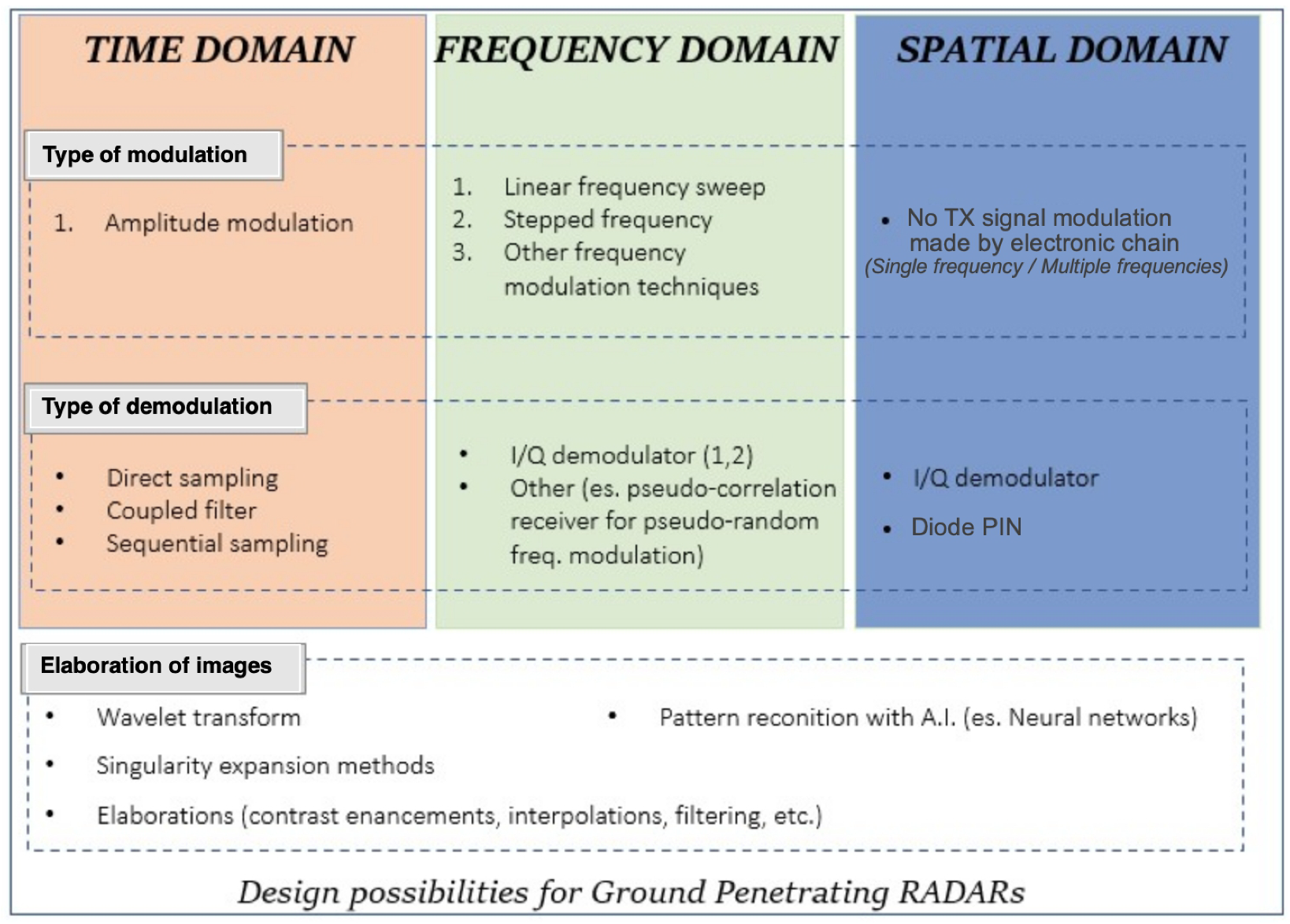
Figure 1. Methods and technolgies for GPR (Ground Penetrating RADAR).
2. Recent Advances in Electronics for Holographic Radars
In optics, the term “hologram” indicates the recording of an interference pattern between two electromagnetic waves, one of which is modulated by diffraction due to the presence of an object (the etymology of the term hologram derives from ancient Greek with the meaning of “whole description” or “whole image” to indicate the possibility it offers to reconstruct the three dimensionality of the scene). The first Holographic Radar made by Keigo Iizuka in the 1960s operated at the microwave frequency of 34 GHz and used Polaroid© film to record holograms [5][6]. From the beginning it was evident that for the inspection of dielectric materials, the attenuation of electromagnetic waves in the microwave range represented a challenge for the electronics design. However, the images recorded by the holographic RADARs have a high spatial resolution in the image plane (≈ λ/4). With the RADAR presented in this entry the spatial resolution is about 3 cm, with medium dielectric permittivity of terrain εr = 6 @ 2 GHz. This resolution is necessary to identify characteristic shapes or details of devices up to 10 cm in diameter [7]. This is the feature that motivated the research to be able to use holographic RADARs in the detection of landmines [8]. As indicated in Figure 1 there is no modulation of the transmitted signal. The modulation in amplitude is constituted by the interference pattern obtained, on the receiving antenna, by the wave transmitted (reference wave) and by the wave reflected from the external environment. In general the microwave hologram is obtained by scanning with the Radar antenna the surface of region of interest and reproducing the recorded amplitude of the holographic signal in the spatial domain. Early receiver electronics was based on a peak detector based on a PIN (P-type, intrinsic, N-type) diode. Then the peak voltage was represented as a color scale for each antenna position to generate an image of the interference pattern. An updated version of the receiver is done using a I/Q (In phase/Quadrature) demodulator. In this type of receiver the output of the holographic RADAR are the I and Q components which allow to calculate the amplitude and phase of the received signal (the hologram Hx,y = Ix,y + iQx,y). With the peak detector based RADARs, researchers obtain a single image that contains the amplitude and phase of the wave front. In this way, the resulting image may not be immediately readable and interpretable and it may be necessary to apply a hologram inversion algorithm to display the three-dimensional image of the scanned target. The electronics based on the I/Q demodulator generate two voltages which are converted into a color scale for each antenna position. The two images obtained represent the amplitude and phase of the hologram. This simplifies and speeds up the reading and interpretation of the information contained in the hologram.
In holographic RADARs it is necessary to correlate samples with space. In the first electronics, spatial correlation of the samples was performed using an ADC board to acquire the samples at specific antenna positions. The ADC was activated by a position encoder. Figure 2 shows the internal architecture of the holographic RADAR “RASCAN 5”. This electronics are built using discrete components and custom hybrid microwave circuits. It is an electronics optimized for the operating frequencies in the range of 6.4 GHz – 6.8 GHz and cannot be reconfigured for other types of antenna/frequency.
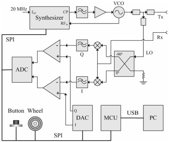
Figure 2. Block diagram of RASCAN-5 electronic architecture.
For the recording of the antenna position during a manual scan with RASCAN radars the adopted solution was a wheel encoder. The sampling step was assigned by the wheel encoder characteristics related to the radar wavelength but cannot be changed for adapting to different radar configurations. For minimizing the spatial sampling errors of manual scan, which depend on both the skills of the operator and from the topography of the investigated surface, the authors proposed the solution of spatial sampling with a remotely controlled robotic platform [9]. The RADAR presented in this work is designed to work with the antenna not in contact with the investigated medium and the acquisition of samples always takes place on a plane with a robotic positioning system. The holographic RADAR used in [10] requires 30 min to cover a 0.75 m2 area by a radial acquisition. To increase the speed of acquisitions, it is necessary to mount the antenna on a two- or three-axial mechanical scanning frame. For the spatial positioning of the RADAR samples, the mechanical frame generates a trigger signal when the antenna arrives in predefined positions in the scanning plane that activates the sampling of the ADC. Figure 3 shows the block diagram of the HSR (Holographic Subsurface RADAR) which was developed during NATO SPS G-5014. This architecture was researchers' starting point for the development of the device presented here. The signal to be radiated originates from a voltage controlled sinusoidal signal generator (VCO: Voltage Controlled Oscillator) in the frequency range (1.97–2.2) GHz. The signal is fed into a directional coupler, whose coupled output forms the reference signal for the I/Q demodulator. The non-attenuated output of the directional coupler is conducted to port 1 of a circulator. The signal exits the consecutive port (port 2) and arrives at the antenna feed. The signal strength is that provided by the VCO, about 7.5 dBm. The signal is radiated and received by the single feed monostatic antenna [11]. The transmitted signal is separated from that received by a three-port circulator. Components I and Q are obtained from a demodulator, using the signal at the output of the directional coupler as a reference. The above components of the complex signal are sampled by the STM32 ARM micro-controller © CortexTM-M7 with a 12-bit analog-digital converter and encoded for storage in a BAG type file, a file format used for storing information and sensor data within the ROS (Robot Operating System) framework.
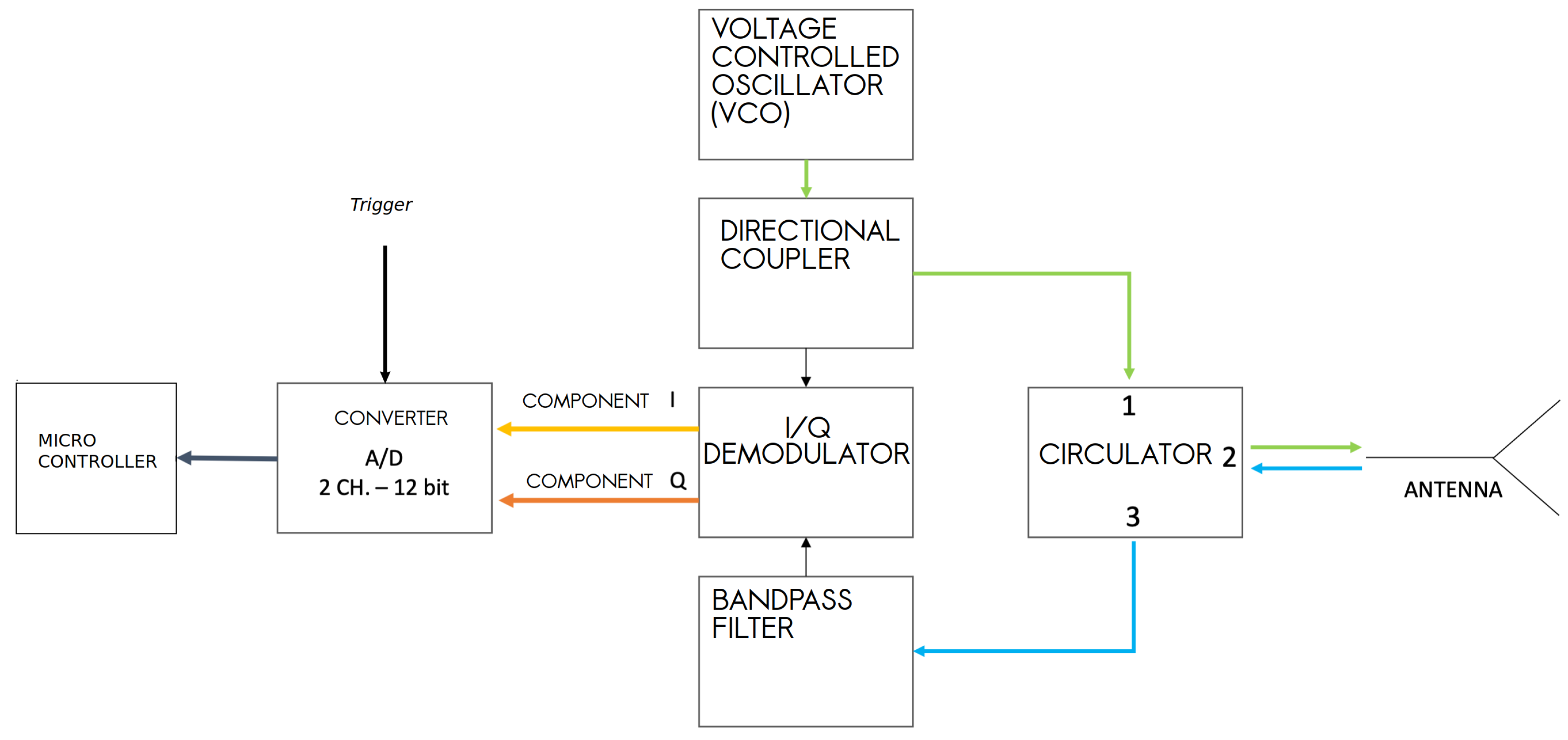
Figure 3. Block diagram of the electronics for a microwave processing the signal of a MW HSR.
The formation of the RADAR image occurs thanks to the spatial positioning of the acquired samples in the coordinates of the programmed grid of points ( Figure 4).
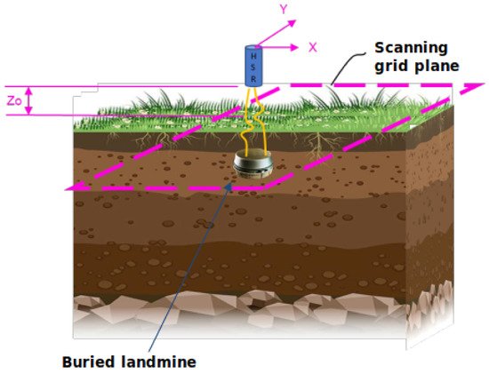
Figure 4. Illustration of the geometry of holographic acquisition. In blue the holographic RADAR antenna that is moved by the mechanical scanning frame (not illustrated) on the scanning plane (dashed pink rectagle) on fixed positions (a grid of 5 mm step).
Synchronization occurs thanks to the trigger for the ADC generated by the mechanical scanning system. For the construction of the holographic image it is therefore necessary to align the samples according to the scanning path followed by the antenna. This path must be known and predefined. Furthermore, it is not possible, other than mechanically, to apply filters on the signal, modify the sampling frequency of the ADC, adjust the signal levels according to the type of medium investigated or use different antennas.
The development of electronic systems based on microwaves, ADC and FPGA integrated circuits for the Software Defined Radio (SDR) have suggested to design a new electronics for the holographic RADAR, which allow to modify the electronics parameters via software. In the rest of the text, the project and the realization of a new architecture for holographic RADAR are presented. The RADAR is designed to work in conjunction with a mechanical scanning frame. This architecture, based on Analog Devices “ADALM Pluto” SDR, allows one to acquire an area of 33 cm × 17 cm in less than 2.5 min, with any scan path for the antenna. In addition, the electronic parameters programmable via software extend the versatility of this type of RADAR, tuning its performance to the type of terrain [2][12], or more generally of the radiated medium. With an SDR device it is possible to adjust the gain or attenuation, activate custom signal filters, decide the bandwidth, the waveform of the transmitted signal and many more.
Starting from the motivation for the choice of the “ADALM Pluto” device and showing its main features, the entry describes the choices for the type of programming code and the software architecture. The entry ends with presentation of the holographic microwaves images obtained with the scan of a plastic case landmine in a soil. Finally the advantages of the new electronics based on SDR technology are outlined.
References
- Ivashov, S. Wide-span systems of mine detection. In Proceedings of the Second International Conference on Detection of Abandoned Land Mines, Edinburgh, UK, 12–14 October 1998; Volume 1998, pp. 78–80.
- Daniels, D.J.; Daniels, D.J.; Institution of Electrical Engineers (Eds.) Ground Penetrating Radar, 2nd ed.; Number 15 in IEE Radar, Sonar, Navigation, and Avionics Series; OCLC: ocm56442546; Institution of Electrical Engineers: London, UK, 2004.
- Borgioli, G.; Bossi, L.; Capineri, L.; Falorni, P.; Bechtel, T.; Crawford, F.; Inagaki, M.; Pochanin, G.; Ruban, V.; Varyanitza-Roschupkina, L.; et al. A Hologram Reconstruction Algorithm for Landmine Recognition and Classification Based on Microwave Holographic Radar Data. In Proceedings of the 2018 Progress in Electromagnetics Research Symposium (PIERS-Toyama), Toyama, Japan, 1–4 August 2018; pp. 1938–1944.
- Sato, M. Dual Sensor ALIS for Humanitarian Demining and its Evaluation Test in Mine Fields in Croatia. In Proceedings of the IGARSS 2008-2008 IEEE International Geoscience and Remote Sensing Symposium, Boston, MA, USA, 6–11 July 2008; pp. II-181–II-184.
- Iizuka, K. Microwave hologram by photoengraving. Proc. IEEE 1969, 57, 813–814.
- Iizuka, K.; Gregoris, L.G. Application of Microwave Holography in the Study of the Field from a Radiating Source. Appl. Phys. Lett. 1970, 17, 509–512.
- Ivashov, S.I.; Razevig, V.V.; Vasiliev, I.A.; Zhuravlev, A.V.; Bechtel, T.D.; Capineri, L. Holographic Subsurface Radar of RASCAN Type: Development and Applications. IEEE J. Sel. Top. Appl. Earth Obs. Remote Sens. 2011, 4, 763–778.
- Sahli, H.; Bottoms, A.M.; Cornelis, J.; EUDEM2 (Project); Society for Counter Ordnance Technology; Vrije Universiteit Brussel (Eds.) EUDEM2-SCOT, 2003, Proceedings of the International Conference on Requirements and Technologies for the Detection, Removal and Neutralization of Landmines and UXO, Brussels, Blegium, 15–18 September 2003; OCLC: 500237233; Vrije Universiteit Brussel: Brussels, Blegium, 2003.
- Capineri, L.; Arezzini, I.; Calzolai, M.; Windsor, C.G.; Inagaki, M.; Bechtel, T.D.; Ivashov, S.I. High Resolution Imaging with a Holographic Radar Mounted on a Robotic Scanner. In Proceedings of the Electromagnetics Research Symposium Proceedings, Stockholm, Sweden, 12–15 August 2013.
- Song, X.J.; Su, Y.; Huang, C.L.; Lu, M.; Zhu, S.P. Landmine detection with holographic radar. In Proceedings of the 2016 16th International Conference on Ground Penetrating Radar (GPR), Hong Kong, China, 13–16 June 2016; pp. 1–4.
- Bossi, L.; Falorni, P.; Priori, S.; Olmi, R.; Capineri, L. Numerical Design and Experimental Validation of a Plastic 3D-Printed Waveguide Antenna for Shallow Object Microwave Imaging. Sens. Imaging 2021, 22, 22.
- Bechtel, T.; Truskavetsky, S.; Capineri, L.; Pochanin, G.; Simic, N.; Viatkin, K.; Sherstyuk, A.; Byndych, T.; Falorni, P.; Bulletti, A.; et al. A survey of electromagnetic characteristics of soils in the Donbass region (Ukraine) for evaluation of the applicability of GPR and MD for landmine detection. In Proceedings of the 2016 16th International Conference on Ground Penetrating Radar (GPR), Hong Kong, China, 13–16 June 2016; pp. 1–6.
More
Information
Subjects:
Engineering, Electrical & Electronic
Contributors
MDPI registered users' name will be linked to their SciProfiles pages. To register with us, please refer to https://encyclopedia.pub/register
:
View Times:
897
Revisions:
2 times
(View History)
Update Date:
14 Oct 2022
Table of Contents


Notice
You are not a member of the advisory board for this topic. If you want to update advisory board member profile, please contact office@encyclopedia.pub.
OK
Confirm
Only members of the Encyclopedia advisory board for this topic are allowed to note entries. Would you like to become an advisory board member of the Encyclopedia?
Yes
No
${ textCharacter }/${ maxCharacter }
Submit
Cancel
Back
Comments
${ item }
|
${ item.createdUser.fullName }
${ item.createdAt }
${ item.vote }
${ item.reply }
Delete
${ reply.createdUser.fullName }
${ reply.createdAt }
${ reply.vote }
Delete
There is no reply to this comment~
${ item.replyTextCharacter }/${ item.replyMaxCharacter }
Submit
Cancel
More
No more~
There is no comment~
${ textCharacter }/${ maxCharacter }
Submit
Cancel
${ selectedItem.replyTextCharacter }/${ selectedItem.replyMaxCharacter }
Submit
Cancel
Confirm
Are you sure to Delete?
Yes
No