Your browser does not fully support modern features. Please upgrade for a smoother experience.
Submitted Successfully!
 +1 credit
Thank you for your contribution! You can also upload a video entry or images related to this topic.
For video creation, please contact our Academic Video Service.
| Version | Summary | Created by | Modification | Content Size | Created at | Operation |
|---|---|---|---|---|---|---|
| 1 | Md. Sazib Mollik | -- | 2293 | 2022-09-14 07:35:22 | | | |
| 2 | Conner Chen | -12 word(s) | 2281 | 2022-09-15 10:09:46 | | | | |
| 3 | Conner Chen | Meta information modification | 2281 | 2022-09-16 08:23:35 | | |
Video Upload Options
We provide professional Academic Video Service to translate complex research into visually appealing presentations. Would you like to try it?
Cite
If you have any further questions, please contact Encyclopedia Editorial Office.
Mollik, M.S.; Hannan, M.A.; Reza, M.S.; Rahman, M.S.A.; Lipu, M.S.H.; Ker, P.J.; Mansor, M.; Muttaqi, K.M. Issues and Challenges of Solid-State Transformer Technology. Encyclopedia. Available online: https://encyclopedia.pub/entry/27155 (accessed on 17 July 2026).
Mollik MS, Hannan MA, Reza MS, Rahman MSA, Lipu MSH, Ker PJ, et al. Issues and Challenges of Solid-State Transformer Technology. Encyclopedia. Available at: https://encyclopedia.pub/entry/27155. Accessed July 17, 2026.
Mollik, Mohammad Sazib, Mahammad A. Hannan, Md Subbir Reza, Muhamad Safwan Abd Rahman, Molla Shahadat Hossain Lipu, Pin Jern Ker, Muhamad Mansor, Kashem M. Muttaqi. "Issues and Challenges of Solid-State Transformer Technology" Encyclopedia, https://encyclopedia.pub/entry/27155 (accessed July 17, 2026).
Mollik, M.S., Hannan, M.A., Reza, M.S., Rahman, M.S.A., Lipu, M.S.H., Ker, P.J., Mansor, M., & Muttaqi, K.M. (2022, September 14). Issues and Challenges of Solid-State Transformer Technology. In Encyclopedia. https://encyclopedia.pub/entry/27155
Mollik, Mohammad Sazib, et al. "Issues and Challenges of Solid-State Transformer Technology." Encyclopedia. Web. 14 September, 2022.
Copy Citation
Solid-state transformer (SST) technology is one of the developing technologies that will be widely used in the future to integrate low-voltage and high-voltage networks with control circuitries and power electronics converters, facilitating renewables integration in smart grid applications. SST technology has crucial key advantageous features, including compact size and weight, low cost, and ease of connection in offshore applications. However, SST technology exhibits a few concerns, such as implementation, protection, economic, and communication compatibility, that need to be addressed.
solid-state transformers
advanced control and operation
power converters
power grids
1. Introduction
Transformers are commonly employed in power supply systems to convert AC voltage and galvanically isolate components. Smart grids are drawing the attention of many researchers recently. They are different from traditional electric networks in that they have power-generating capabilities and are able to supply electricity, especially to responsible customers in emergencies. Electricity may be generated from various sources, including nuclear power plants, autonomous diesel–electric units, large batteries, wind farms, solar panels, and hydrogen fuel cells. When employing multiple energy sources in smart grids, different stress levels should be coordinated. This is more challenging, since a portion of electrical energy is generated or stored in DC systems while the remaining is in AC systems. There are no enhancements or alterations to the classic transformer; thus, if the input voltage is asymmetrical and variations in frequency are present, there will also be an adverse effect on the output voltage. Traditional transformers need rectifiers and inverters to operate with networks that utilize a different direct or alternating current [1][2]. Solid-state transformers (SSTs) can be employed to address these concerns in smart grids, which can control and enhance the quality of electricity by compensating reactive power and reducing voltage drops. Using this technology, power supply can be adjusted without using any added compensator. SSTs are more compact, making it simpler to match varied voltage levels of direct and alternating currents. A few recent studies of SSTs with focused areas and research gaps are shown in Table 1.
Table 1. Research topics and key factors of SST technology.
| Ref. | Year | Focused Topics | Key Factors |
|---|---|---|---|
| [3] | 2021 | This research proposes a DC–DC converter for a hybrid AC/DC SST. Multilevel, bidirectional, and four-port are the critical features of the proposed DC–DC converter. | Research issues and difficulties, as well as contemporary trends, are not taken into account. |
| [4] | 2021 | A unique construction based on bidirectional multilevel power converters on both sides of the SST, and the suggested SST’s applicability to hybrid power networks. | The authors did not refer in the article to any research gaps. Therefore, the difficulties associated with research and validation are not well addressed. |
| [5] | 2021 | A modern traction system used SST technology in smart grid applications and distributed generating sources like solar and wind. | This research ignores the problems and difficulties that may arise. Sustainability and dependability were not given sufficient attention. The control system was ignored. |
| [6] | 2021 | The background of hybrid alternating current/direct current grids in future power grids, their inherent problems and possibilities, and how to maximize power transfer | The article does not detail the research gap and lack of power quality. |
SST technology connects the distribution system with the electrical users in future smart grid systems. In the smart grid system, an SST connects the medium-voltage distribution system (e.g., 12 kV AC) to the low-voltage AC distribution (e.g., 120 V AC) and/or DC distribution system (e.g., 400 V DC), as depicted in Figure 1.
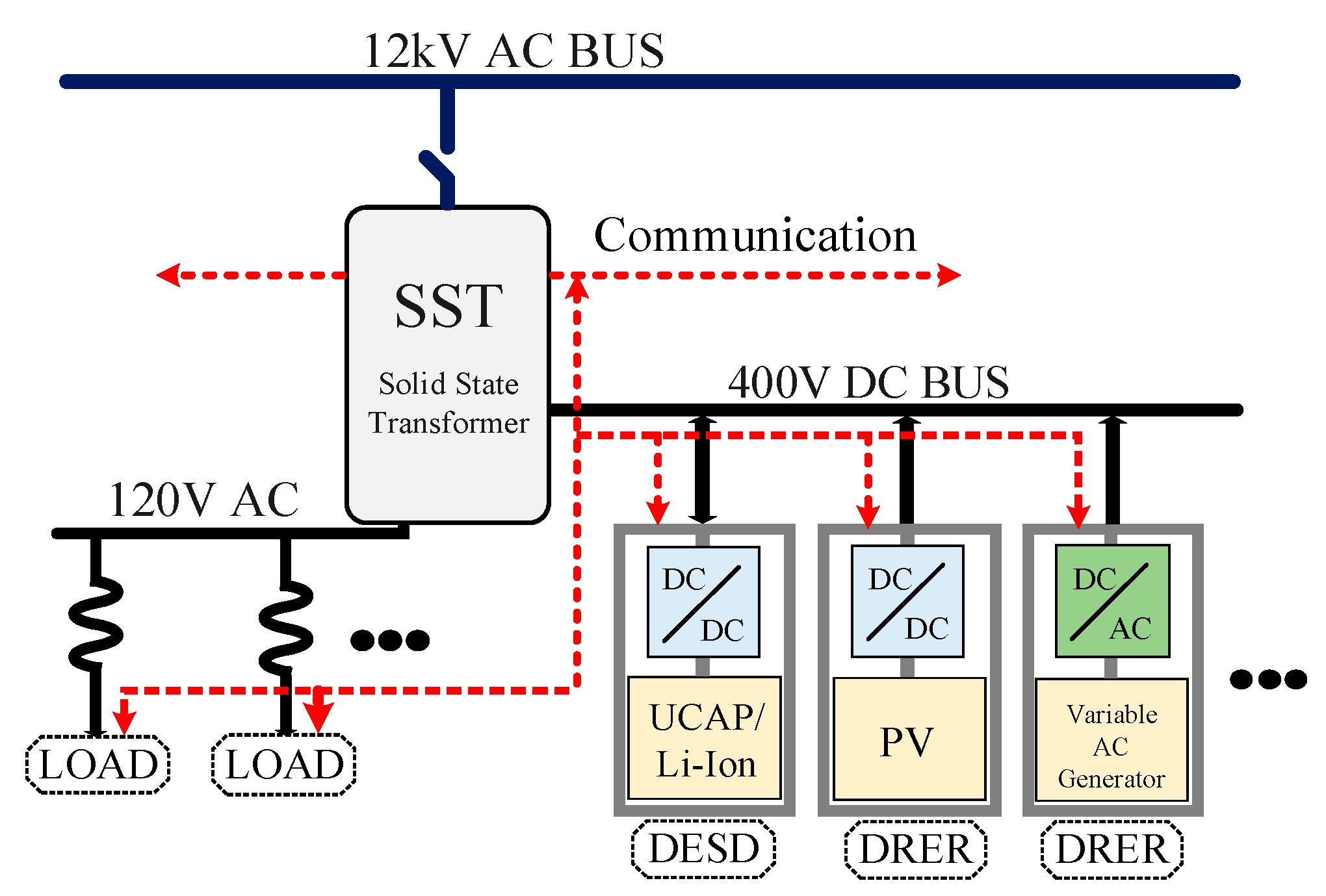
Figure 1. Solid–State Transformer at one residential home.
When a 60 Hz conventional transformer cannot be utilized to control distributed renewable energy resources (DRER), distributed energy storage devices (DESD), or loads, the SST can be used instead. The characteristics of SSTs include immediate voltage control, voltage sag compensation, fault isolation, power factor correction, harmonic isolation, and a direct current output [7]. The 400 V DC port on the SST makes it easier to connect certain types of DRERs and DESDs [8]. Each SST, which functions as an energy router, can control active and reactive power flow as well as fault currents on both the low- and high-voltage sides. In addition, it has enormous control bandwidth capability that enables remote resources to control and respond to changes in the system quickly. According to Figure 2, an SST is made up of three parts: an active rectifier, an active bridge converter that goes in both directions from DC to DC, and an inverter [9]. The most appealing qualities of SSTs are found in the last three phases. As a result, the SST may draw a unity power factor or offer reactive compensation for voltage control when connected to the grid.
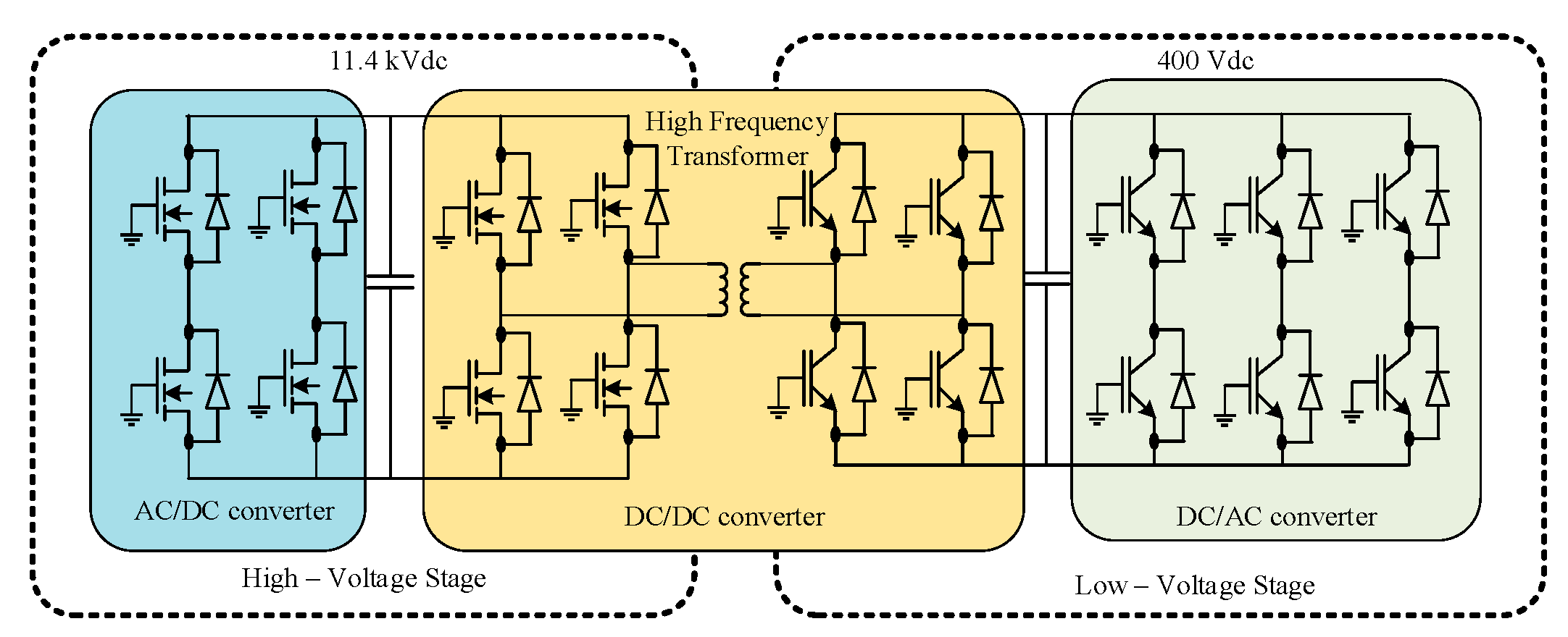
Figure 2. SST at one residential home.
The filtering on the load side can also separate the load from transient swells and harmonic distortion on the AC grid. Another benefit of using low-voltage (LV) direct current (DC) is that it may serve as a DC bus for solar panels, energy storage devices, or electric vehicle chargers. These new capabilities and flexibility provide a foundation for future smart grid infrastructure development. However, the addition of numerous power electronic converters to a standard AC grid brings a variety of previously unrecognized control and stability difficulties. SST interactions have the potential to generate instability, which is a problem. The source output impedance interacts with the input impedance to produce this instability, manifesting as harmonic resonance. An SST’s active front end (the high-voltage (HV) rectifier) appears to the AC grid as a constant power load regardless of client load composition [10]. When the voltage drops, the power consumption reduces, making constant impedance loads self-correcting. In contrast, continuous power loads use the same amount of power and are frequently referred to as “negative impedances”, which can cause DC networks to become unstable if they are not correctly constructed [11].
2. Issues and Challenges of SST Technology
2.1. Conversion Efficiency Challenge
LFTs in distribution grids are primarily responsible for providing galvanic isolation and voltage scaling while incurring as few losses as possible. As a result, for the majority of the load range, typical oil-filled 1000 kVA LFT efficiencies exceed 99% according to [12]; taking other manufacturers into account produces similar findings.
On the other hand, an AC–AC SST contains two AC–AC converter stages, one on each side of the primary voltage and voltage supply: one for the main voltage and one for the low voltage (LV) (as seen in Figure 3). Based on the provided LFT and MFT efficiencies and assuming that the two AC–AC converter stages have identical efficiencies (i.e., SST, MV = SST, LV), The efficiencies of the AC¬¬–AC stages required to obtain an overall SST efficiency equal to an LFT, i.e., SST = LFT, are determined in this research. The choice of an optimal switching frequency is critical to this efficiency and the active material size. It is essential to keep in mind that MFTs may get away with using less material and being more efficient than LFTs because their prices are lower. It is important to note that even with a high-efficiency MFT (ηMFT = 99.6%), getting to the desired total MV-to-LV efficiency of 99.5% necessitates 99.7% efficiencies in both AC–AC conversion stages (Figure 3). As you can see, this is a lofty goal that will likely remain unachievable with current high-power converters.
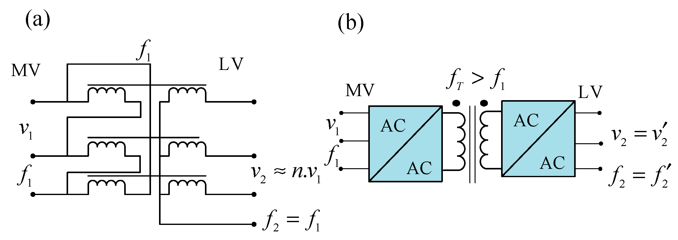
Figure 3. Diagrams of a standard SST: (a) low-frequency distribution transformer with a delta-wye connection (LFT), (b) SST.
2.2. Cost Challenge
According to pricing information collected from a prominent European transformer manufacturer, LFTs are off-the-shelf commodities with a specified (selling) price between cLFT = 10 $/kVA and 25 $/kVA for 1000 kVA units [13]. The price will differ based on the optimization goal, such as low losses or cheap costs; for instance, there are not any SST products on the market that allow you compare their pricing side by side. Therefore, [14] SST materials are estimated to be at least five times more expensive than LFT materials for a 1000 kVA SST.
A product’s cost of production does not have to be directly tied to the price because there may be other factors at play, such as compensation for development expenses, labor expenses in manufacturing, infrastructure costs, and profit margins, among other things. Since high-power converter systems are widely accessible, their pricing may be used to estimate the cost of an SST. An SST’s LV inverter (as depicted in Figure 4) is essentially the same as a high-power drive’s active front-end (AFE) converter, such as the Altivar 61 series from Schneider Electric [12].
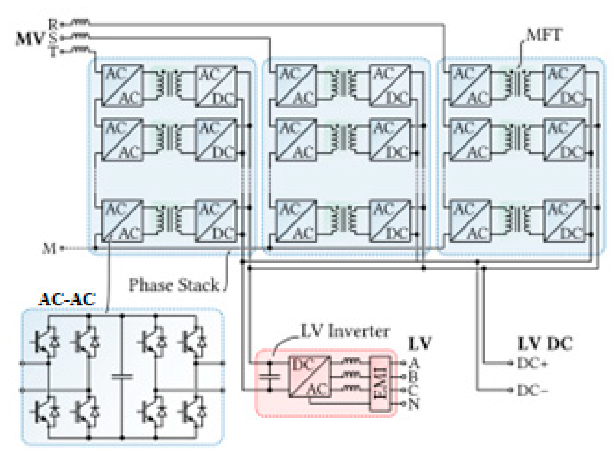
Figure 4. Typical topology of an MV/LV SST employing a cascaded converter structure on the MV side to handle the high voltage levels. Note that the AC–AC stages at the cascaded cells’ MV sides can feature a local DC link (AC–DC–AC-structure as shown in the figure) or be of a matrix-type (direct AC–AC conversion).
For these converters, price information is available, and a 1000 kVA unit costs roughly cSST,LV = 125 $/kVA [12]. Furthermore, [15] The cost of the utility-scale (500 kVA) PV inverters ranges from 100 to 120 euros per kVA (114 to 137 dollars per kVA).
Because the MV-side converter section is more complicated and must interface with MV as well as contain the MF isolation stage, it is reasonable to suppose that the MV-side converter’s particular price is greater than the LV-side converter’s, i.e., cSST,MV > cSST,LV.
The weight and material cost structures of the MV converter, the LV converter. It is noteworthy that low-frequency magnetic components, such as filter inductors, continue to account for a sizable portion of both weight and material costs, particularly in the case of LV converters, where high phase currents necessitate large copper conductor material requirements. Consequently, these passive filter components are of special importance for future cost and weight reductions of SSTs. However, future technologies such as silicon carbide (SiC) are anticipated to considerably contribute to additional weight reduction via greater switching frequencies and subsequently smaller passive component sizes. Medium-frequency transformers and power semiconductors also contribute significantly to material expenses [14].
2.3. Compatibility Challenge
Most of the time, fuses and circuit breakers that may be programmed are used to safeguard low-voltage grids against short circuits. When an issue arises, only the nearest upstream protection device should activate, limiting the grid’s impact to the lowest possible region. In this defense strategy, selectivity is crucial. Figure 6a depicts a simplified form of a hierarchically arranged LV grid and associated protective devices. To achieve selectivity, fuse ratings are low near end-users and higher near the feeding transformer. Figure 5b depicts the relationship between melting time and current consumption for a common low-voltage (LV) fuse [16], a fuse with a lower-rated current trips before a fuse with a higher rating when a short circuit develops, indicating that a short circuit occurred. Even a similarly small 250 A fuse would take a long time to light, for which, within a reasonable time, a current of around 1.5IN may be required to safeguard a load on a lower hierarchical level of the LV grid, as illustrated in Figure 5b. A short-circuit current that is several times the rating value is needed for fuses that are closer to the feeding transformer because they are installed at the higher level of the LV grid’s hierarchical structure. This is particularly true for the transformer safety fuses, which are positioned close to the transformers. The transformers at the MV grid’s interface must provide the short-circuit current needed. There is a two-second time limit on the maximum current that LFTs should be able to supply [17].
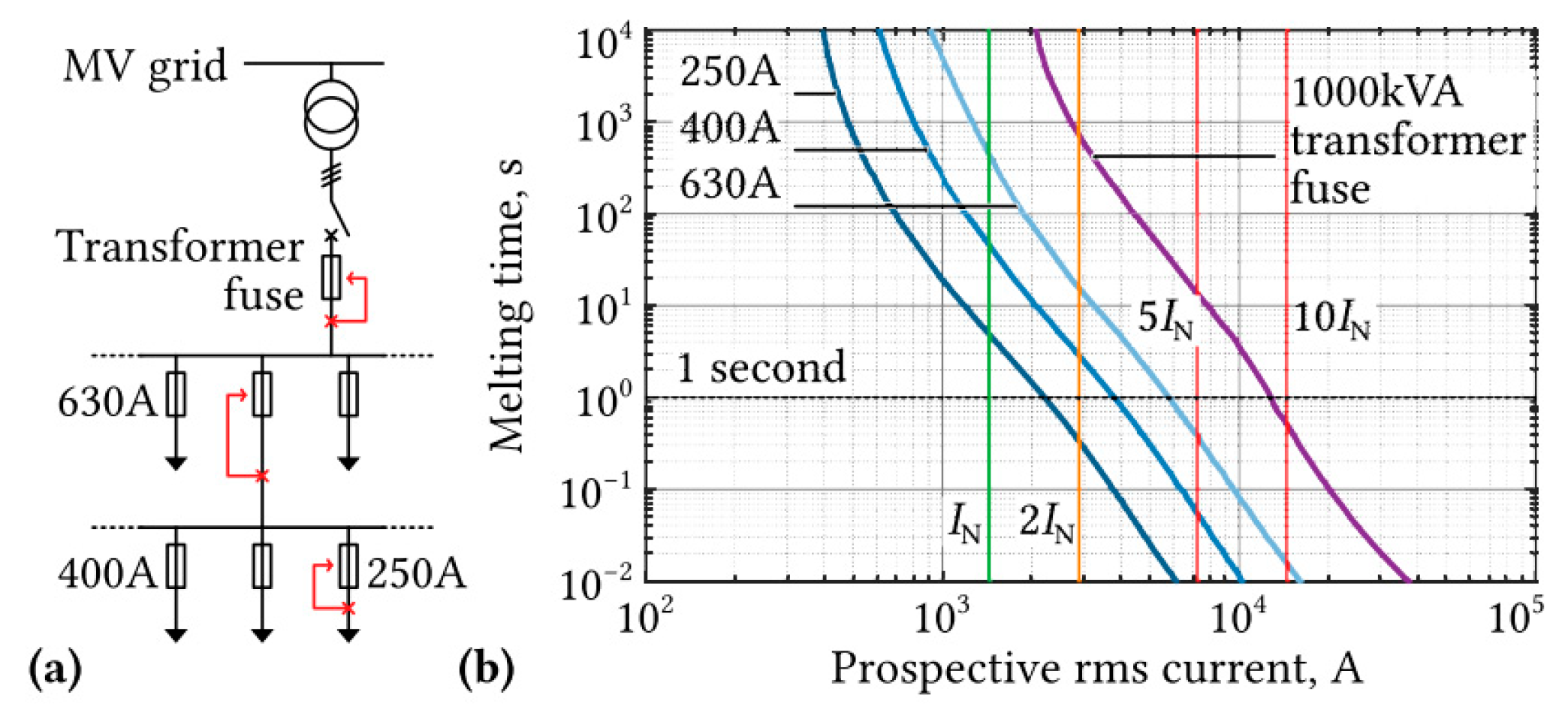
Figure 6. (a) Fuse and selectivity indications at various branching levels in a typical LV grid arrangement; (b) Melting time of LV fuses with different rated currents vs. current characteristics and a fuse for a 1000 kVA transformer in relation to its nominal current and its SST for a 1000 kVA transformer or LFT [17].
In contrast, a power electronic system cannot achieve this without significantly overrating the power devices due to the power semiconductor chip thermal time constants, which are only 10 to 50 milliseconds; additionally, the filter inductors would need to have a correspondingly high saturation limit. [18]. On the other hand, an SST might restrict the current flow during a short circuit. However, security ideas are necessary to make use of this intriguing capability. Communication between the breakers, SST, or other grid-connected switching devices is regularly employed in these intricate protection approaches. [19][20][21][22]. This means that an SST would have to be used with an LFT in the distribution grid because the present protection architecture could not be used any longer. As opposed to this, an SST needs a grid environment tailored to the SST’s special properties such as communication between protection relays. However, implementing such changes would be difficult in current distribution systems, and they would be costly.
2.4. System Topologies
The topologies of current converters designed for railway traction applications were investigated. Numerous alternative topologies, on the other hand, such as isolated AC-to-AC converter topologies, can be identified by a survey and study of isolated converter topologies [23][24][25][26][27][28][29][30]. Smart grid and renewable energy applications research is now gaining pace. Due to commonality in high power, medium voltage, and galvanic isolation, PET-based systems intended for smart grid and renewable energy applications are highly likely to be transferred to railway traction applications.
2.5. Other Issues
Beyond the three critical problems outlined above, blockchain is an emerging technology that faces several other challenges. The operating frequency and the number of cascaded modules’ optimization may be less complicated. However, it still requires more investigation, as do the techniques of soft switching and control and system dependability and protection. Furthermore, these problems might impact one another and form a symbiotic relationship. For example, with the advancement of power devices, people may create new converter topologies and increase the number of cascaded modules and power devices people have. As a result, rather than focusing on an individual component, it is critical to assess the impacts at the system level.
References
- Almaguer, J.; Cárdenas, V.; Espinoza, J.; Aganza-Torres, A.; González, M. Performance and control strategy of real-time simulation of a three-phase solid-state transformer. Appl. Sci. 2019, 9, 789.
- Chernyi, S. Techniques for selecting topology and implementing the distributed control system network for maritime platforms. AKCE Int. J. Graphs Comb. 2018, 15, 219–223.
- Monteiro, V.; Oliveira, C.; Afonso, J.L. A Multilevel Bidirectional Four-Port DC-DC Converter to Create a DC-Grid in Solid-State Transformers with Hybrid AC/DC Grids. In Proceedings of the International Young Engineers Forum (YEF-ECE), Caparica/Lisboa, Portugal, 9 July 2021; pp. 26–31.
- Monteiro, V.; Pedrosa, D.; Coelho, S.; Sousa, T.; Machado, L.; Afonso, J.L. A Novel Multilevel Solid-State Transformer for Hybrid Power Grids. In Proceedings of the International Conference on Smart Energy Systems and Technologies (SEST), Vaasa, Finland, 6–8 September 2021; pp. 1–6.
- Shadfar, H.; Ghorbani Pashakolaei, M.; Akbari Foroud, A. Solid-state transformers: An overview of the concept, topology, and its applications in the smart grid. Int. Trans. Electr. Energy Syst. 2021, 31, e12996.
- Monteiro, V.; Martins, J.S.; Fernandes, J.C.A.; Afonso, J.L. Review of a Disruptive Vision of Future Power Grids: A New Path Based on Hybrid AC/DC Grids and Solid-State Transformers. Sustainability 2021, 13, 9423.
- Shi, J.; Gou, W.; Yuan, H.; Zhao, T.; Huang, A.Q. Research on voltage and power balance control for cascaded modular solid-state transformer. IEEE Trans. Power Electron. 2011, 26, 1154–1166.
- Zhao, T.; Wang, G.; Bhattacharya, S.; Huang, A.Q. Voltage and power balance control for a cascaded H-bridge converter-based solid-state transformer. IEEE Trans. Power Electron. 2013, 28, 1523–1532.
- Shah, D.G.; Crow, M.L. Stability design criteria for distribution systems with solid-state transformers. IEEE Trans. Power Deliv. 2014, 29, 14759118.
- Bottrell, N.; Prodanovic, M.; Green, T.C. Dynamic stability of a microgrid with an active load. IEEE Trans. Power Electron. 2013, 28, 5107–5119.
- Onwuchekwa, C.N.; Kwasinski, A. Dynamic behavior of single-phase full-wave uncontrolled rectifiers with instantaneous constant-power loads. In Proceedings of the IEEE Energy Conversion Congress and Exposition, Phoenix, AZ, USA, 17–22 September 2011; pp. 3472–3479.
- Strasser, T.; Andrén, F.; Kathan, J.; Cecati, C.; Buccella, C.; Siano, P.; Leitão, P.; Zhabelova, G.; Vyatkin, V.; Vrba, P.; et al. A review of architectures and concepts for intelligence in future electric energy systems. IEEE Trans. Ind. Electron. 2015, 62, 2424–2438.
- Saleh, S.A.; Richard, C.; Onge, X.F.S.; McDonald, K.M.; Ozkop, E.; Chang, L.; Alsayid, B. Solid-state transformers for distribution systems—Part I: Technology and construction. IEEE Trans. Ind. Appl. 2019, 55, 4524–4535.
- Huber, J.E.; Kolar, J.W. Volume/weight/cost comparison of a 1MVA 10 kV/400 V solid-state against a conventional low-frequency distribution transformer. In Proceedings of the IEEE Energy Conversion Congress and Exposition (ECCE), Pittsburgh, PA, USA, 14–18 September 2014; pp. 4545–4552.
- Guillod, T.; Krismer, F.; Kolar, J.W. Protection of MV converters in the grid: The case of MV/LV solid-state transformers. IEEE J. Emerg. Sel. Top. Power Electron. 2016, 5, 393–408.
- Kabalcı, E. Solid state transformers with multilevel inverters. In Multilevel Inverters; Elsevier: Amsterdam, The Netherlands, 2021; pp. 249–266.
- Zheng, L.; Han, X.; Kandula, R.P.; Kandasamy, K.; Saeedifard, M.; Divan, D. 7.2 kV three-port single-phase single-stage modular soft-switching solid-state transformer with active power decoupling and reduced dc-link. In Proceedings of the IEEE Applied Power Electronics Conference and Exposition (APEC), New Orleans, LA, USA, 15–19 March 2020; pp. 1575–1581.
- Avdeev, B.; Vyngra, A.; Chernyi, S. Improving the electricity quality by means of a single-phase solid-state transformer. Designs 2020, 4, 35.
- Krismer, T.G.F.; Färber, R.; Franck, C.M.; Kolar, J.W. Protection of MV/LV solid-state transformers in the distribution grid. In Proceedings of the IECON 41st Annual Conference of the IEEE Industrial Electronics Society, Yokohama, Japan, 9–12 November 2015; pp. 003531–003538.
- Shi, H.; Wen, H.; Hu, Y.; Yang, Y.; Wang, Y. Efficiency optimization of DC solid-state transformer for photovoltaic power systems. IEEE Trans. Ind. Electron. 2020, 67, 3583–3595.
- Li, R.; Xu, L.; Yao, L.; Williams, B.W. Active control of DC fault currents in DC solid-state transformers during ride-through operation of multi-terminal HVDC systems. IEEE Trans. Energy Convers. 2016, 31, 1336–1346.
- Gorla, N.B.Y.; Kolluri, S.; Chai, M.; Panda, S.K. A comprehensive harmonic analysis and control strategy for improved input power quality in a cascaded modular solid state transformer. IEEE Trans. Power Electron. 2019, 34, 6219–6232.
- Wei, Q.; Wu, B.; Xu, D.; Zargari, N.R. A medium-frequency transformer-based wind energy conversion system used for current-source converter-based offshore wind farm. IEEE Trans. Power Electron. 2017, 32, 248–259.
- Cardenas, R.B.; Molinas, M. Comparative study of wind turbine power converters based on medium-frequency AC-link for offshore DC-grids. IEEE J. Emerg. Sel. Top. Power Electron. 2015, 3, 525–541.
- Krishnamoorthy, H.S.; Rana, D.; Garg, P.; Enjeti, P.N.; Pitel, I.J. Wind turbine generator–battery energy storage utility interface converter topology with medium-frequency transformer link. IEEE Trans. Power Electron. 2014, 29, 4146–4155.
- Dannier, A.; Rizzo, R. An overview of Power Electronic Transformer: Control strategies and topologies. In Proceedings of the International Symposium on Power Electronics, Electrical Drives, Automation and Motion, Sorrento, Italy, 20–22 June 2012; pp. 1552–1557.
- Chen, H.; Prasai, A.; Moghe, R.; Chintakrinda, K.; Divan, D. A 50-kVA three-phase solid-state transformer based on the minimal topology: Dyna-C. IEEE Trans. Power Electron. 2016, 31, 8126–8137.
- Kouro, S.; Malinowski, M.; Gopakumar, K.; Pou, J.; Franquelo, L.G.; Wu, B.; Rodriguez, J.; Pérez, M.A.; Leon, J.I. Recent advances and industrial applications of multilevel converters. IEEE Trans. Ind. Electron. 2010, 57, 2553–2580.
- Rahman, M.A.; Islam, M.R.; Muttaqi, K.M.; Sutanto, D. Data-Driven Coordinated Control of Converters in a Smart Solid-State Transformer for Reliable and Automated Distribution Grids. IEEE Trans. Ind. Appl. 2020, 56, 4532–4542.
- Qin, H.; Kimball, J.W. Solid-state transformer architecture using AC–AC dual-active-bridge converter. IEEE Trans. Ind. Electron. 2013, 60, 3720–3730.
More
Information
Subjects:
Engineering, Electrical & Electronic
Contributors
MDPI registered users' name will be linked to their SciProfiles pages. To register with us, please refer to https://encyclopedia.pub/register
:
View Times:
4.2K
Revisions:
3 times
(View History)
Update Date:
16 Sep 2022
Table of Contents


Notice
You are not a member of the advisory board for this topic. If you want to update advisory board member profile, please contact office@encyclopedia.pub.
OK
Confirm
Only members of the Encyclopedia advisory board for this topic are allowed to note entries. Would you like to become an advisory board member of the Encyclopedia?
Yes
No
${ textCharacter }/${ maxCharacter }
Submit
Cancel
Back
Comments
${ item }
|
${ item.createdUser.fullName }
${ item.createdAt }
${ item.vote }
${ item.reply }
Delete
${ reply.createdUser.fullName }
${ reply.createdAt }
${ reply.vote }
Delete
There is no reply to this comment~
${ item.replyTextCharacter }/${ item.replyMaxCharacter }
Submit
Cancel
More
No more~
There is no comment~
${ textCharacter }/${ maxCharacter }
Submit
Cancel
${ selectedItem.replyTextCharacter }/${ selectedItem.replyMaxCharacter }
Submit
Cancel
Confirm
Are you sure to Delete?
Yes
No