
| Version | Summary | Created by | Modification | Content Size | Created at | Operation |
|---|---|---|---|---|---|---|
| 1 | Dong xuan yi | -- | 8649 | 2022-09-08 04:29:33 | | | |
| 2 | Dong xuan yi | + 258 word(s) | 8907 | 2022-09-16 14:10:04 | | | | |
| 3 | Dong xuan yi | -1063 word(s) | 2500 | 2022-09-26 05:29:11 | | | | |
| 4 | Rita Xu | -44 word(s) | 2456 | 2022-09-28 02:56:30 | | |
Video Upload Options
The utilization of various distributed energy is becoming a prominent research topic due to the rapid development of the Internet of Things and wireless condition monitoring systems. Among the various distributed energy sources, wind energy has the advantages of being widely distributed, renewable and pollution-free, and is a very promising mechanical energy for power supply. Traditional wind energy harvesting methods based on electromagnetic and piezoelectric effects have issues with complex structure, large size, severe mechanical structures, and high installation costs. The low frequency and irregular nature of ambient mechanical energy makes these methods generally inefficient and inevitably hinders the further exploitation of wind energy. The triboelectric nanogenerators (TENGs) based on frictional charging and electrostatic effects can also be used for wind power generation and are increasingly favored by researchers as TENGs are easier to be miniaturized and assembled, and can realize large-scale manufacturing in comparison.
1. Introduction
With the worldwide commitment to promote carbon-free power generation, wind power is becoming an increasingly important part of human daily life and is of great importance for the sustainable development of human society [1][2][3]. In 2012, Dr. Zhong Lin Wang proposed a new energy collection method—triboelectric nanogenerator, which is particularly suitable for the harvesting of irregularly distributed low mechanical frequency vibrational energy such as wind energy [4][5][6]. The concept of a wind-driven triboelectric nanogenerator (WD-TENG) has been developed to take advantages of the characteristics of wind energy and the high conversion efficiency of TENG.
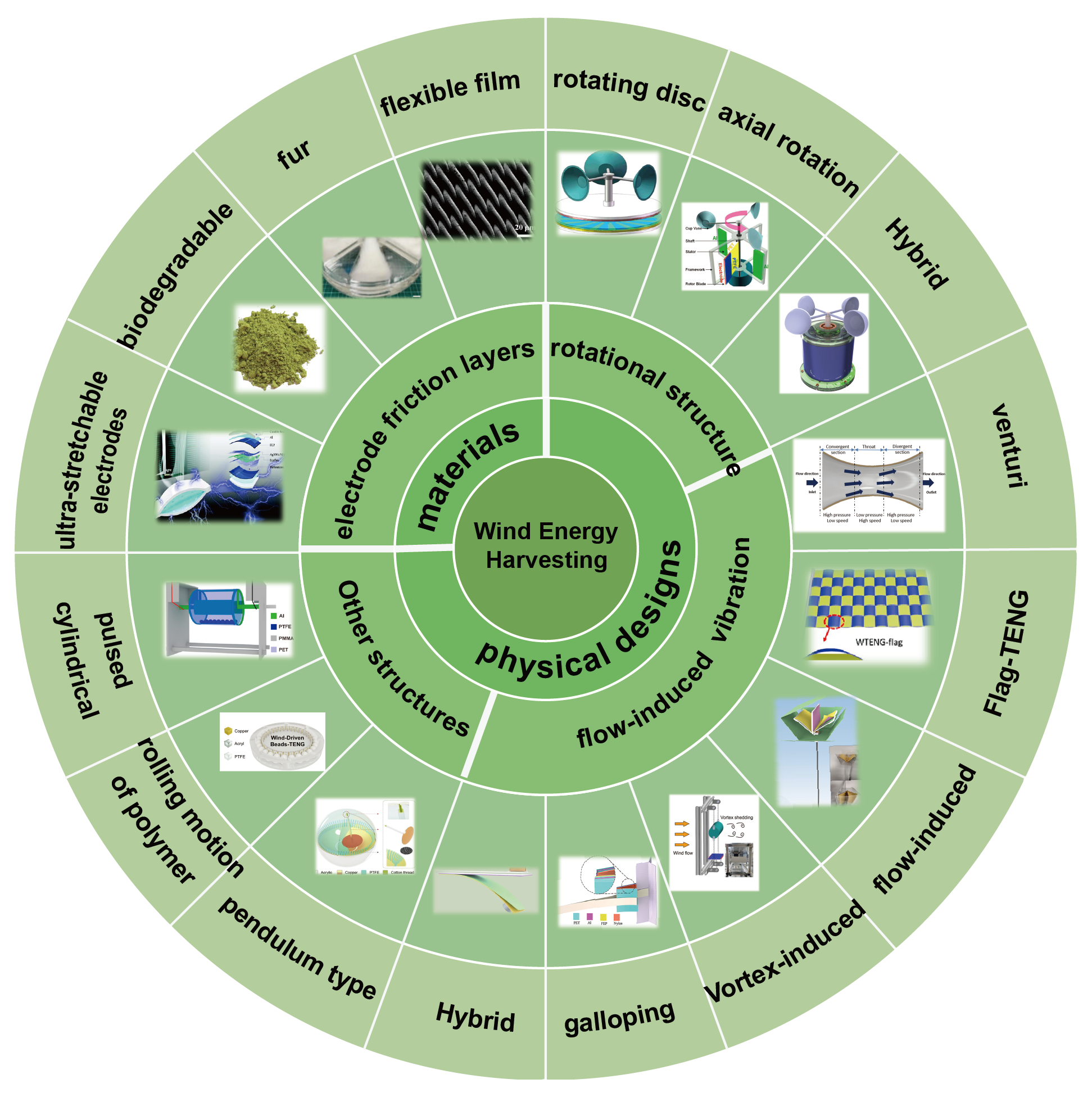
As shown in Figure 1, to summarize recent work in the TENG for wind energy harvesting and sensing and, most importantly, to explore possible new key areas to help guide the future direction of the TENG in fluid dynamics sensing by addressing key challenges.
2.Historical Research and Progress of WD-TENG
2.1. Material Electrification Mechanism
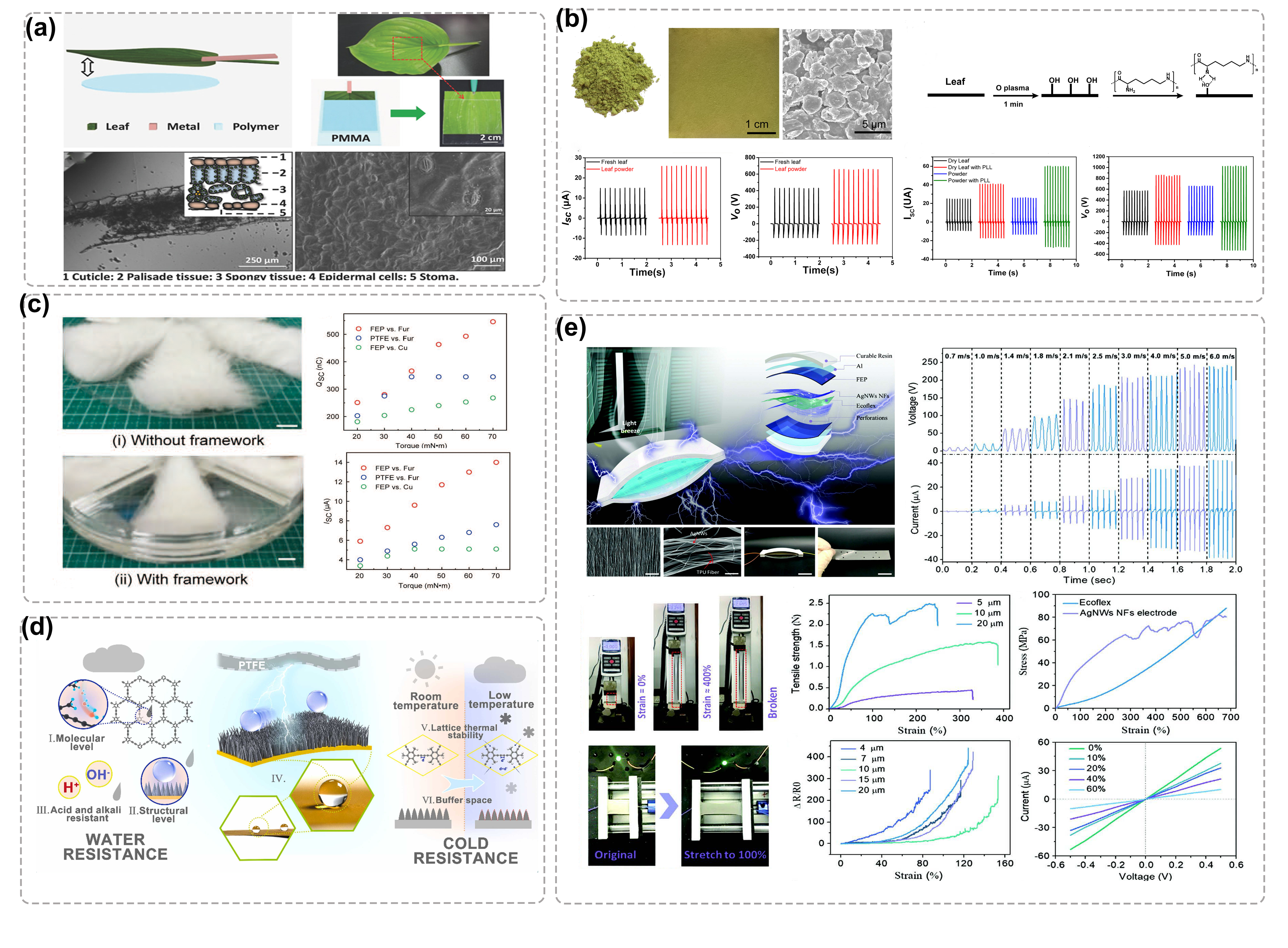
The materials utilized to make WD-TENG must not only be widely apart in the triboelectric sequence, but they must also be resilient, durable, and cost-effective. Table 1 lists the classification, advantages and disadvantages of the materials commonly used in the production of WD-TENG. And Figure 2 illustrates the various types of materials mentioned in Table 1.
| Classification | Categories | Advantages | Disadvantages |
|---|---|---|---|
| Metals and its derivatives | Metal, alloy, semiconductor metallic nanoflakes/nanoparticles/nanowires | Excellent electrical conductivity,high stability,high mechanical robustness,simple process | Low flexibility |
| Conducting polymers | PTFE, PVDF, PDMS, PMMA | Easy structural control,heat resistance,corrosion resistance,light weight,good flexibility | Relatively high cost,poor conductivity,low stability,Non-biodegradable,Not-recyclable |
| Carbonaceous fillers | Graphite, CNT, Graphdiyne | High conductivity,high stability,good mechanical properties | Cumbersome processing technology |
| Natural materials | Rabbit Fur, leaves | Flexible,low cost,biodegradable and easy to process | Poor electrical conductivity,poor durability |
| Composite materials | Combination of different conductive materials(e.g., graphene-PDMS) | Synergistic effect | Increased preparation cost and workload |
2.2. Utilization Mechanism of Mechanical Energy
2.2.1. Infrastructure and principles
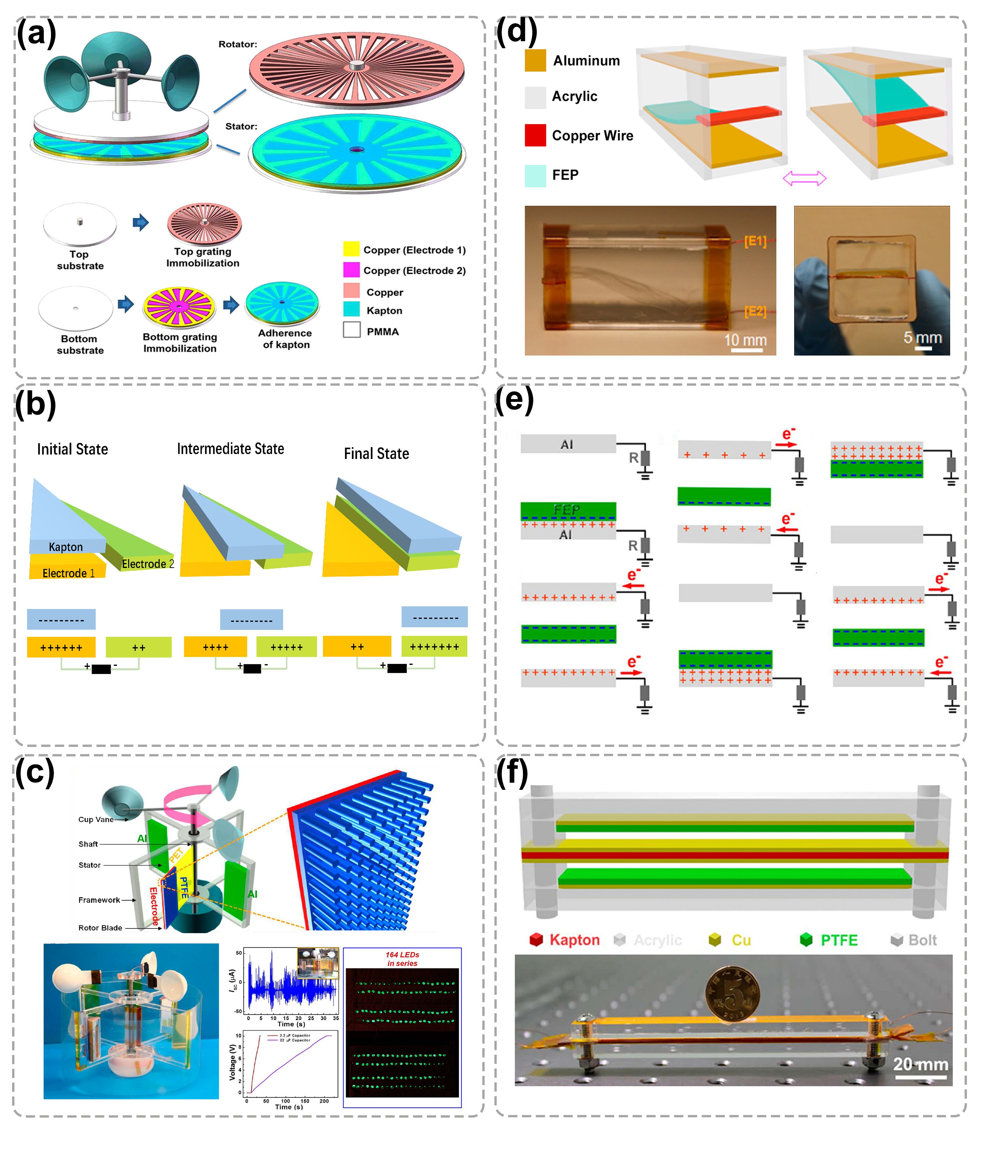
TENG used for wind energy collection can be divided into “rotary type” and “flow induced vibration type”[25][26][27] according to the way of energy collection. The structural design of rotating wind energy collection TENG is mainly inspired by the traditional electromagnetic wind turbine, with the help of wind cup or other structures to collect wind energy, and convert it into rotating mechanical energy to drive the contact separation of TENG friction layer, so as to produce electrical output. Wind energy collection devices based on rotating structure usually have dense peak output and high output power, mostly in the form of separate layers and rotating slides. Figure 3a-c shows a typical rotating slip structure. Although rotary wind energy collection can effectively realize wind power generation, such devices must first convert wind energy into rotary kinetic energy before driving TENG to work. There is a large energy loss in this process. As a result, scientists prefer to convert the flowing wind energy directly into the device’s vibration energy, which is why the flow-induced TENG was invented [28]. Figure 3d-f shows the basic structure and principle of the flow-induced TENG.
2.2.2. Structural display of WD-TENG
For the rotating disc type WD-TENG, researchers adopted methods such as transiting the operating mode from contact to non-contact and optimizing the rotation axis length to improve its performance. In addition, Flow-excited vibrations offer significant advantages in the field of miniaturization, integrated wind energy harvesting devices and the harvesting of breeze energy. Four flow-induced vibration phenomena are generally used to convert fluid energy into mechanical kinetic energy: vortex vibration, galloping, flutter and wake-galloping. Based on these theories, researchers have been constantly updating their structures to improve the efficient use of wind energy in recent years. Figure 4 shows these structures. And Figure 5 illustrates some of the special structures.
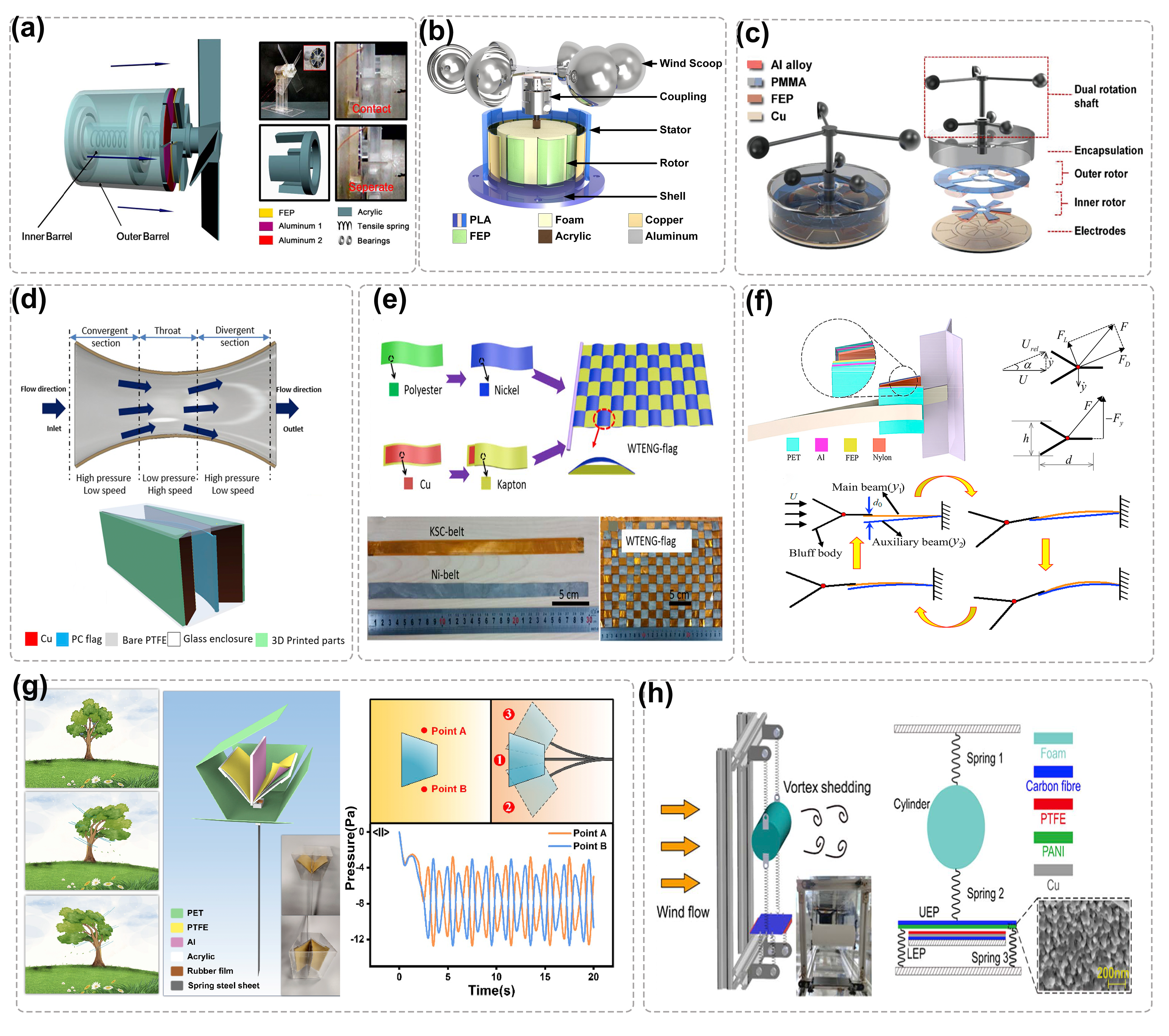
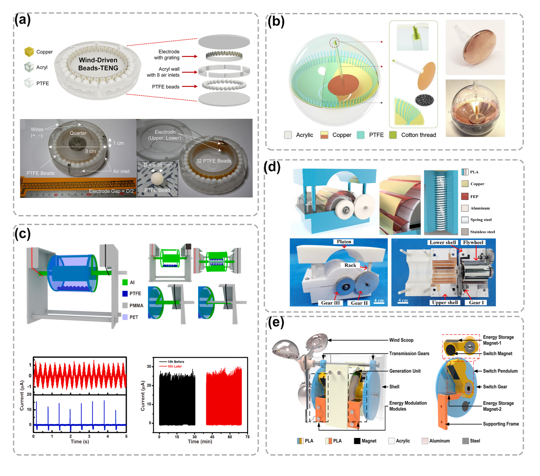
Figure 5. Other structures of WD-TENG. (a) WD-TENG based on rolling motion of beads. Reproduced with permission of [17], Copyright 2018, Elsevier. (b) A pendulum-spired WD-TENG. Reproduced with permission of [16], Copyright 2019, Elsevier. (c) A pulsed cylindrical WD-TENG. Reproduced with permission of [18], Copyright 2021, Elsevier. (d) A bidirectional gear transmission triboelectric nanogenerator (BGT-TENG). Reproduced with permission of [34], Copyright 2020, Elsevier. (e) WD-TENG controlled energy collection by magnetic switch. Reproduced with permission of [35], Copyright 2021, Elsevier.
4. Applications of WD-TENG
As the designs of WD-TENG become smaller, lighter, and more durable, they become more adaptable to varying wind speeds, humidity, and other external environmental conditions . WD-TENG shows great potential in various applications such as powering small electronic devices, as secondary energy stored in capacitors, as self-powered sensors for wind vectors or parameters such as humidity, and self-powered electrochemical systems, as depicted in Figure 6a–f.
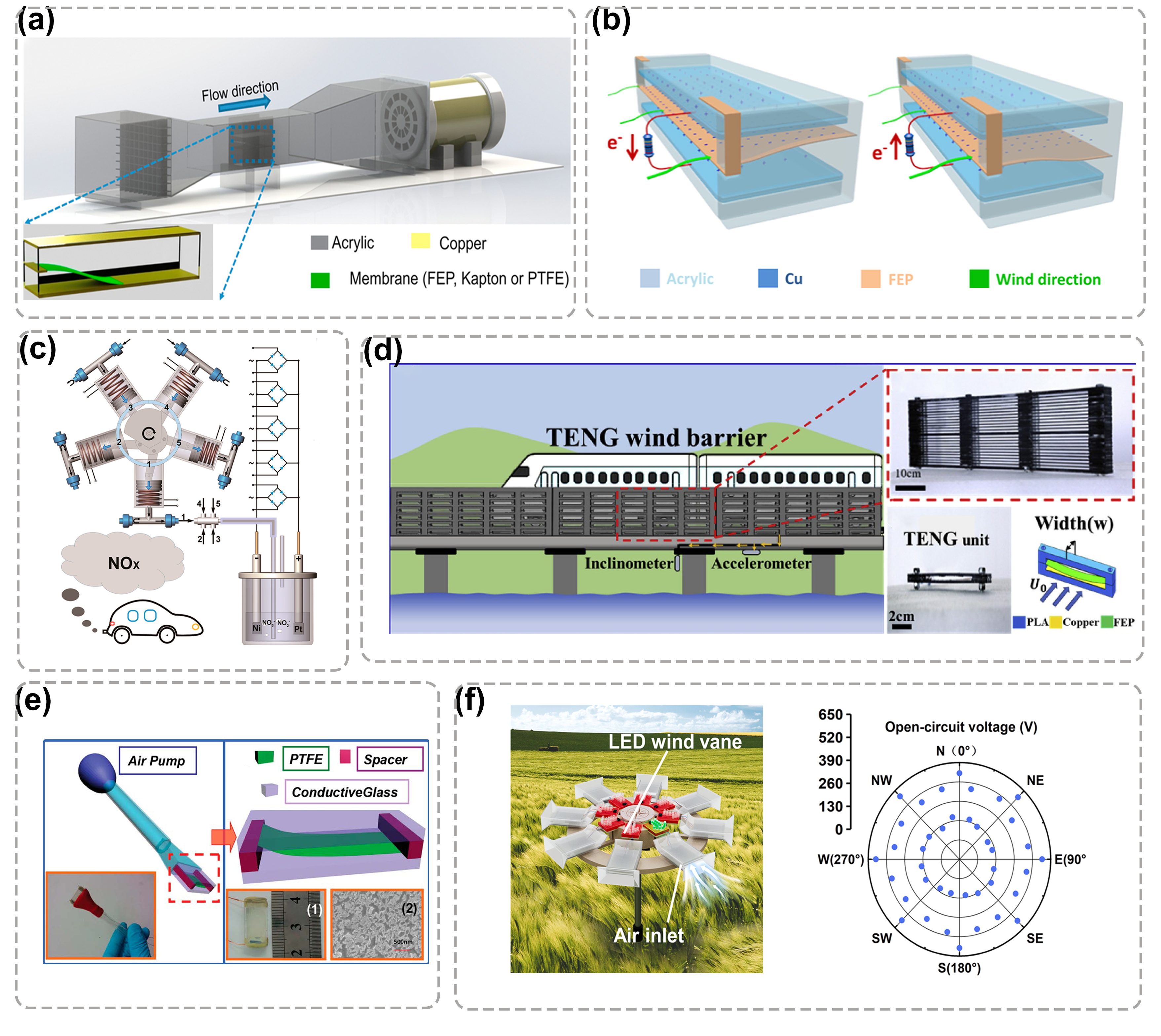
Figure 6. Applications of WD-TENG. (a) Experimental set-up and characterization of fluttering behavior of AF-TENG. Reproduced with permission of [36], Copyright 2017, Elsevier. (b) Schematic diagram and working mechanism of ferroelectric BTO disk polarized by WD-TENG. Reproduced with permission of [37], Copyright 2017, Elsevier. (c) Self-powered air purification system. Reproduced with permission of [38], Copyright 2020, ACS Nano. (d) Application scenario of the TENG-based wind barrier. Reproduced with permission of [39], Copyright 2020, Nano Energy. (e) Schematic diagram and (inset) digital photograph of the designed ATNG sensor. Reproduced with permission of [40], Copyright 2014, American Chemical Society. (f) WD-TENG is used to realize self-powered wind vector monitoring. Reproduced with permission of [41], Copyright 2021, Elsevier.
5. WD-TENG Hybridized with Other Types of Generators
In order to realize the complementary advantages of various energy conversion mechanisms in obtaining mechanical energy and self-powered sensing, the combination of TENGs with electromagnetic and piezoelectric energy collection mechanisms is con-sidered. Figure 7a-d shows its structure when combined with various energy conversion mechanisms in pyroelectric, piezoelectric and photoelectric. Among these mixing mechanisms, the most common is the mixing between TENG and EMG. Figure 8 shows the comparison of output performance between TENG and EMG under rectification, which suggests that the TENG is better suited to derive energy from low frequency motion than the ENG. Figure 9 shows several ways to optimize the combination of EMG and TENG.
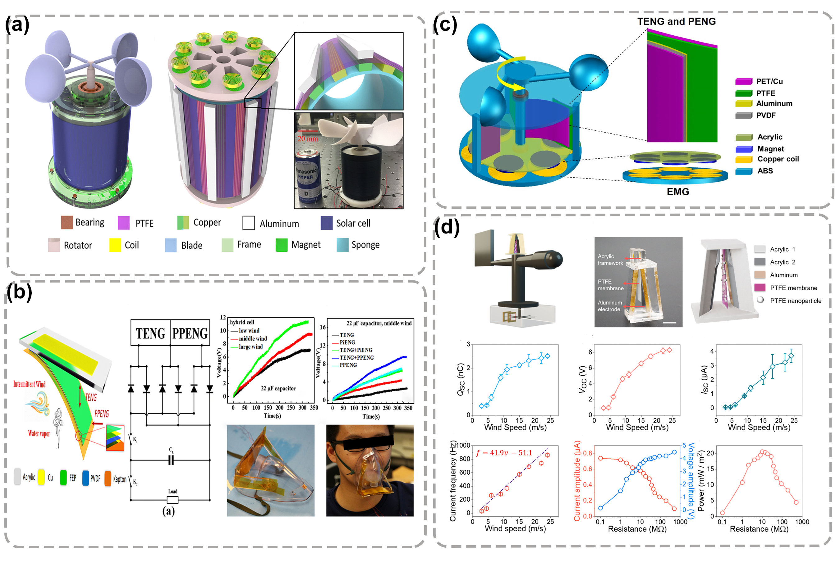
Figure 7. WD-TENG hybridized with other generators. (a) Hybrid TENGs combined with EMG and TENG. Reproduced with permission of [9], Copyright 2018, Elsevier. (b) Hybrid TENGs combined with PPENG and TENG. Reproduced with permission of [42], Copyright 2018, American Chemical Society. (c) Hybrid TENGs combined with PENG and TENG. Reproduced with permission of [43], Copyright 2018, Elsevier. (d) WD-TENG combined with photoelectric technology. Reproduced with permission of [44], Copyright 2021, Elsevier.
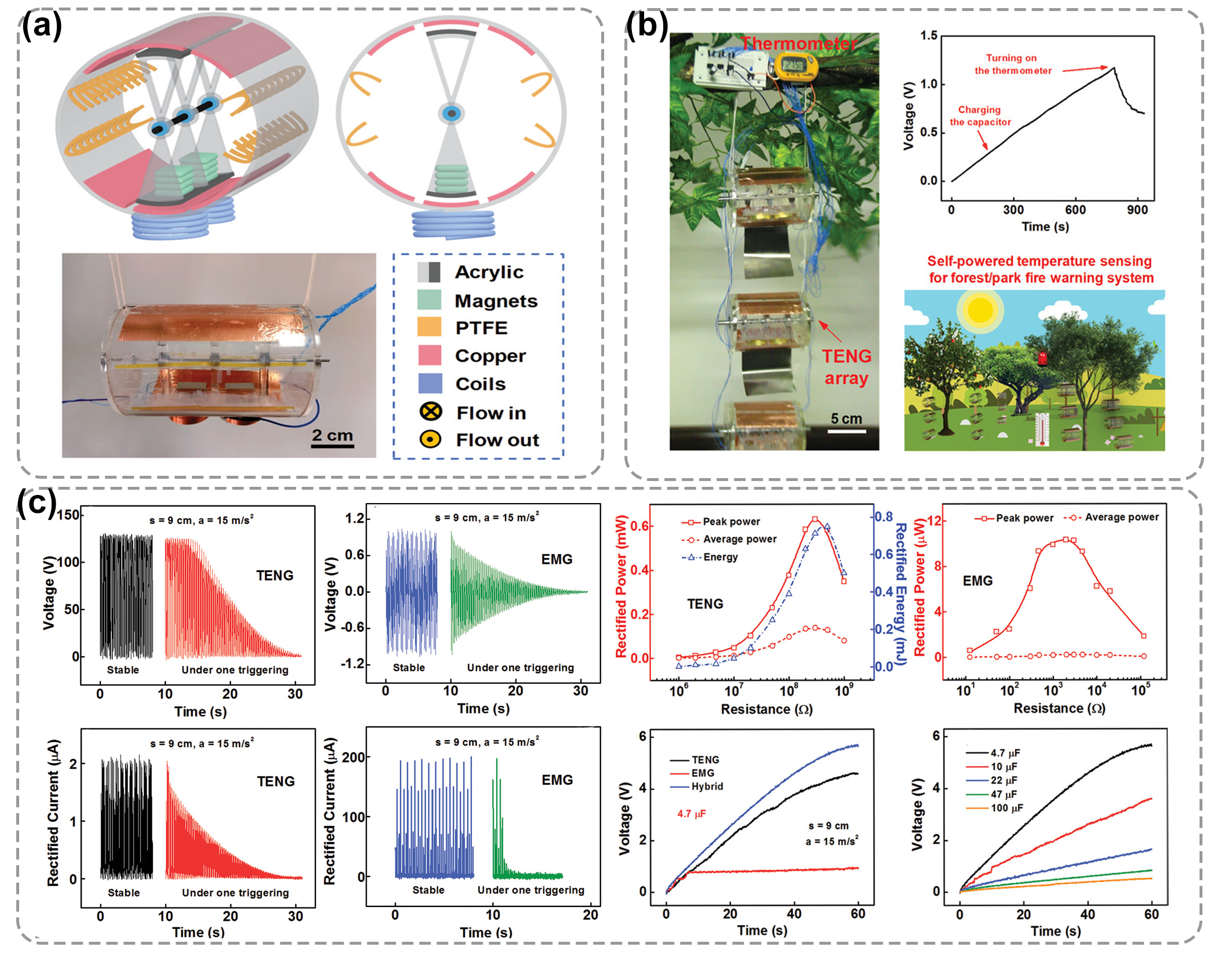
Figure 8. (a) A swinging breeze collection system consisting of EMG and TENG. (b) Photograph of a digital thermometer powered by a SS–TENG array under the wind triggering. (c) Output performance of the TENG part and EMG. Reproduced with permission of [45], Copyright 2021, John Wiley and Sons.
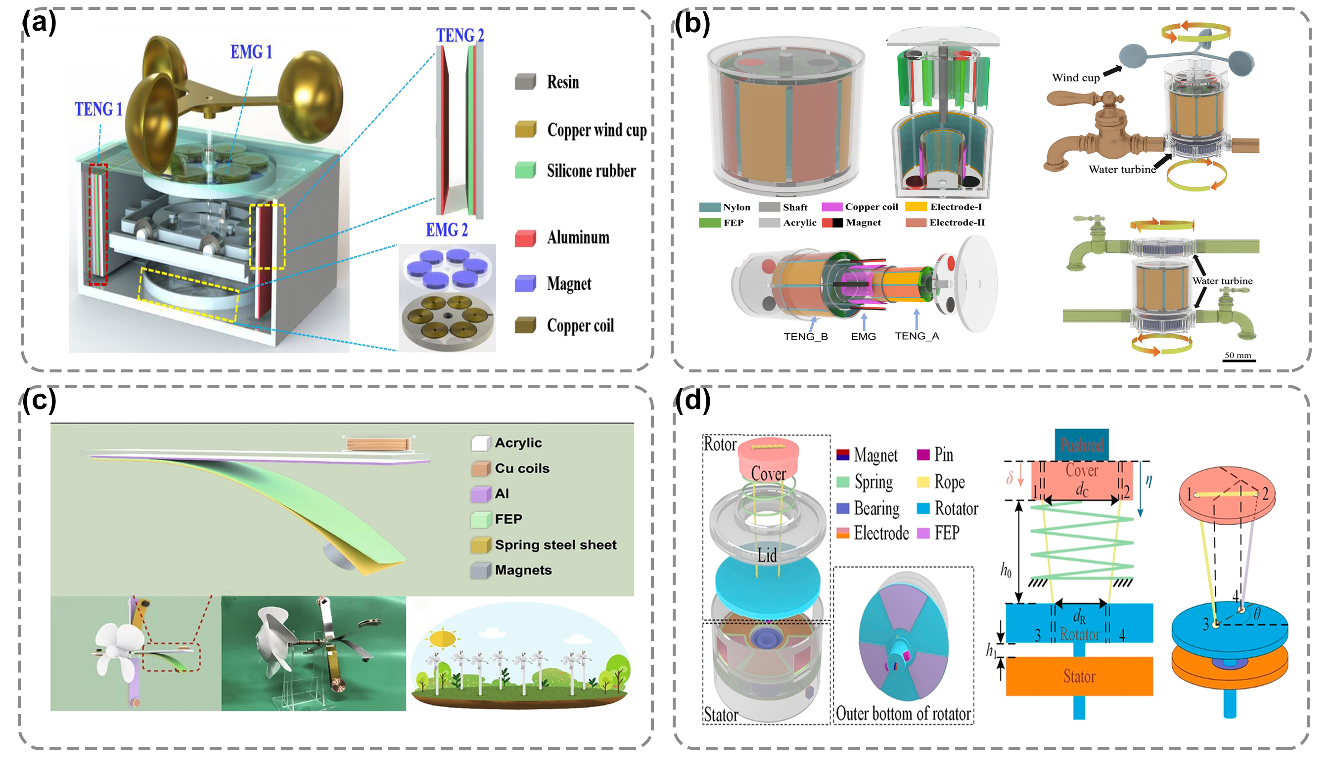
Figure 9. Hybrid TENGs combined with EMG and TENG. (a) The structure of the TEHG. Reproduced with permission of [46], Copyright 2019, Elsevier. (b) Structural design of the MCNG. Reproduced with permission of [47], Copyright 2021, Elsevier. (c) Schematic illustration of the W-HNG. Reproduced with permission of [15], Copyright 2020, Springer. (d) Structure and working principle of the IC-TENG. Reproduced with permission of [48], Copyright 2021, Elsevier.
The selection of WD-TENGs should be made in conjunction with the advantages and disadvantages of the WD-TENG classification in and specific application scenarios. summarizes the reported WD-TENGs suitable for energy harvesting or sensing in breezy environments, and it is observed that wind power generation in low wind environments can be achieved by selecting flexible, low-density materials and optimizing the structure. It is expected that these more detailed presentations can provide methodological guidance and design inspiration for future research and applications of WD-TENGs in breezy environments.
Table 2. Summary and comparison of various WD-TENGs.
Structures |
Triboelectric Materials |
Modes |
Voltage(v) |
Current (uA) |
Power |
Ref |
Rotational sweeping mode |
Al & PTFE |
CS&LS |
250 |
250 |
62.5 mW(900 r/min) |
[8] |
Rotational sweeping mode |
Al & PTFE |
SE |
55 |
– |
0.03 mW |
[49] |
Rotational sweeping mode |
Al & PVDF |
FT |
650 |
50 |
10 mW(900 r/min) |
[50] |
In-plane cycled sliding mode |
Cu & Kapton |
FT |
320 |
3400 |
– |
[7] |
bidirectional gear transmission structure |
FEP & Cu |
CS |
- |
- |
4 mW(50 MΩ) |
[34] |
Transform the rotating structure into a linear structure |
PTFE & Cu |
CS |
200 |
2.9 |
180 μw(1 subunit, 60 rpm) |
[51] |
Transform the rotating structure into a linear structure |
PTFE & Cu |
CS |
320 |
20 |
0.37 mW(6 subunit,60 rpm) |
[52] |
Single-side-fixed |
Al & FEP |
CS |
100 |
1.6 |
0.16 mW(100 MΩ) |
[29] |
Single-side-fixed |
Au & PTFE |
CS |
200 |
60 |
0.86 mW(15 m/s) |
[53] |
Single-side-fixed |
FTO & PTFE |
CS |
36 |
4.1 |
– |
[40] |
Single-side-fixed |
Al & PTFE |
CS |
400 |
60 |
3.7 mW |
[28] |
Single-side-fixed |
FEP & Cu |
CS |
36 |
11.8 |
0.15 mW |
[54] |
Single-side-fixed |
PTFE & Al |
CS |
297 |
- |
0.46 Mw(10 m/s) |
[26] |
Single-side-fixed |
Hosta Leaf & PMMA |
SE |
230 |
9.5 |
45 mW/m2(1 × 107 Ω) |
[23] |
Single-side-fixed |
wheat straw & FEP |
SE |
250 |
20 |
404 μW/m2 |
[55] |
Single-side-fixed |
PTFE & MGDY |
CS |
100 |
3.5 |
- |
[24] |
Single-side-fixed |
PLL modified leaf powder & PVDF |
CS |
1000 |
60 |
17.9 mW(11 MΩ) |
[20] |
Double-side-fixed |
Al & PTFE |
CS |
334 |
67 |
5.5 mW |
[56] |
Double-side-fixed |
Cu &PTFE |
CS |
342 |
140 |
- |
[30] |
Lawn structure |
ITO & PET |
CS |
78 |
16.3 |
- |
[57] |
Angle-shaped |
FEP& Al |
CS |
64 |
2.5 (10 m/s) |
- |
[58] |
Venturi tube |
PTFE& PC |
CS |
- |
- |
4.5 mW(5 m/s) |
[10] |
Flag structure |
Ni & Kapton |
CS |
40 |
30 |
135 mW/kg(22 m/s) |
[11] |
fluttering double-flag type |
FEP & Cu |
CS |
- |
- |
600 mW/m2(10 m/s) |
[59] |
Vortex-induced |
PANI & PTFE |
CS |
- |
- |
96.79 mW/m2(2.78 m/s) |
[13] |
galloping structure |
Nylon & FEP |
CS |
200V(1.4 m/s) |
- |
6 μW(1.4 m/s) |
[14] |
Cantilevered structure |
PTFE & Al |
CS |
270 |
7.6 |
0.9 mW(2.9 m/s,44 MΩ) |
[12] |
rolling motion of polymer beads |
PTFE & Cu |
FT |
17.8 |
5.3 |
1.36 mW/cm2(20 m/s) |
[60] |
structure of the magnetic switch |
FEP & Cu |
FT |
410 |
18 |
4.82 mW |
[35] |
Table 3. Summary and comparison of various WD-TENGs for harvest breeze wind.
Structures |
Triboelectric Materials |
Characteristic |
Start-UpWindSpeed |
Electric Output |
Ref |
Rotational sweeping mode |
FEP &Cu |
Low density rotor material, a suitable wind scoop structure |
3.3 m/s |
330 v, 7 μA;Pmax = 2.81 mW(4 m/s) |
[32] |
Rotational sweeping mode |
FEP &Cu |
Coupling of TENG with different structural parameters |
2.2 m/s |
5.2 mW |
[33] |
Rotational sweeping mode |
FEP &Cu |
Adopt the dielectric film with high flexibility |
3.5 m/s |
- |
[61] |
Vortex-induced vibration |
PANI & PTFE |
wind energy harvesting based on vortex-induced vibration |
2.78 m/s |
392.72 μW |
[13] |
Single-side-fixed |
PTFE &Al |
Controls the thickness and size of the film and the distance between the plates |
3.4 m/s |
297 v; 3.9 μA;P = 0.46 mW(10 m/s) |
[26] |
Single-side-fixed |
PTFE &Al |
By changing the material, size and aspect ratio of the film |
2.9 m/s |
2.06 μW (10 MΩ) |
[44] |
Single-side-fixed |
PTFE & MGDY |
Unique material, film geometry parameter control |
1.6 m/s |
- |
[24] |
Galloping structure |
Nylon & FEP |
Through the design of two flexible beams to achieve galloping behavior |
1 m/s |
6 uW(1.4 m/s) |
[14] |
Cantilevered structure |
Al& PTFE |
Change electrode structure, electrode weight, rotating radius and cantilever length. |
2.9 m/s |
- |
[12] |
Variable diameter channel |
Al & FEP |
A square variable diameter channel combined with an ordinary double-ended fixed W-TENG |
0.4m/s |
2 V(2 m/s) |
[62] |
6. Summary and Outlook
Wind energy is a widely distributed, clean, renewable and green energy source, and wind power is an important direction for future new energy development. Based on the advantages of TENG in collecting irregular low-frequency energy, WD-TENG, a new wind energy harvesting technology, is proposed to realize the effective conversion of wind energy in different applications. The existing single WD-TENG device can generate an output voltage up to 1000V. In addition, WD-TENG can be fabricated with environmentally friend materials and the existing WD-TENG can provide power supply for low-power systems such as LEDs, temperature and humidity sensors, environmental monitor and even air cleaning device. Researchers review the evolution of WD-TENG structure, the latest progress in material selection, and compiles the output performance, advantages and disadvantages of various designs. Then, researchers summarize the desirable methods for WD-TENG to work effectively at different wind speeds. In addition, WD-TENG can work in concert with other mechanisms to broaden its application areas.
References
- A. Cherp, V. Vinichenko, J. Tosun, J.A. Gordon, J. Jewell, National growth dynamics of wind and solar power compared to the growth required for global climate targets, Nat. Energy. 6 (2021) 742–754. https://doi.org/10.1038/s41560-021-00863-0.
- T. Traber, C. Kemfert, Gone with the wind? — Electricity market prices and incentives to invest in thermal power plants under increasing wind energy supply, Energy Econ. 33 (2011) 249–256. https://doi.org/10.1016/j.eneco.2010.07.002.
- A. Ahmed, I. Hassan, M. Hedaya, T. Abo El-Yazid, J. Zu, Z.L. Wang, Farms of triboelectric nanogenerators for harvesting wind energy: A potential approach towards green energy, Nano Energy. 36 (2017) 21–29. https://doi.org/10.1016/j.nanoen.2017.03.046.
- C. Wang, S.-K. Lai, J.-M. Wang, J.-J. Feng, Y.-Q. Ni, An ultra-low-frequency, broadband and multi-stable tri-hybrid energy harvester for enabling the next-generation sustainable power, Appl. Energy. 291 (2021) 116825. https://doi.org/10.1016/j.apenergy.2021.116825.
- T. Lee, I. Kim, D. Kim, Flexible Hybrid Nanogenerator for Self-Powered Weather and Healthcare Monitoring Sensor, Adv. Electron. Mater. 7 (2021) 2100785. https://doi.org/10.1002/aelm.202100785.
- F. Shen, Z. Li, H. Guo, Z. Yang, H. Wu, M. Wang, J. Luo, S. Xie, Y. Peng, H. Pu, Recent Advances towards Ocean Energy Harvesting and Self-Powered Applications Based on Triboelectric Nanogenerators, Adv. Electron. Mater. 7 (2021) 2100277. https://doi.org/10.1002/aelm.202100277.
- S. Chen, C. Gao, W. Tang, H. Zhu, Y. Han, Q. Jiang, T. Li, X. Cao, Z. Wang, Self-powered cleaning of air pollution by wind driven triboelectric nanogenerator, Spec. Issue 2nd Int. Conf. Nanogenerators Piezotronics NGPT 2014. 14 (2015) 217–225. https://doi.org/10.1016/j.nanoen.2014.12.013.
- Y. Xie, S. Wang, L. Lin, Q. Jing, Z.-H. Lin, S. Niu, Z. Wu, Z.L. Wang, Rotary Triboelectric Nanogenerator Based on a Hybridized Mechanism for Harvesting Wind Energy, ACS Nano. 7 (2013) 7119–7125. https://doi.org/10.1021/nn402477h.
- J. Qian, X. Jing, Wind-driven hybridized triboelectric-electromagnetic nanogenerator and solar cell as a sustainable power unit for self-powered natural disaster monitoring sensor networks, Nano Energy. 52 (2018) 78–87. https://doi.org/10.1016/j.nanoen.2018.07.035.
- A.N. Ravichandran, C. Calmes, J.R. Serres, M. Ramuz, S. Blayac, Compact and high performance wind actuated venturi triboelectric energy harvester, Nano Energy. 62 (2019) 449–457. https://doi.org/10.1016/j.nanoen.2019.05.053.
- Z. Zhao, X. Pu, C. Du, L. Li, C. Jiang, W. Hu, Z.L. Wang, Freestanding Flag-Type Triboelectric Nanogenerator for Harvesting High-Altitude Wind Energy from Arbitrary Directions, ACS Nano. 10 (2016) 1780–1787. https://doi.org/10.1021/acsnano.5b07157.
- Q. Zeng, Y. Wu, Q. Tang, W. Liu, J. Wu, Y. Zhang, G. Yin, H. Yang, S. Yuan, D. Tan, C. Hu, X. Wang, A high-efficient breeze energy harvester utilizing a full-packaged triboelectric nanogenerator based on flow-induced vibration, Nano Energy. 70 (2020) 104524. https://doi.org/10.1016/j.nanoen.2020.104524.
- L. Zhang, B. Meng, Y. Tian, X. Meng, X. Lin, Y. He, C. Xing, H. Dai, L. Wang, Vortex-induced vibration triboelectric nanogenerator for low speed wind energy harvesting, Nano Energy. 95 (2022) 107029. https://doi.org/10.1016/j.nanoen.2022.107029.
- L. Zhang, B. Meng, Y. Xia, Z. Deng, H. Dai, P. Hagedorn, Z. Peng, L. Wang, Galloping triboelectric nanogenerator for energy harvesting under low wind speed, Nano Energy. 70 (2020) 104477. https://doi.org/10.1016/j.nanoen.2020.104477.
- Y. Zhang, Q. Zeng, Y. Wu, J. Wu, S. Yuan, D. Tan, C. Hu, X. Wang, An Ultra-Durable Windmill-Like Hybrid Nanogenerator for Steady and Efficient Harvesting of Low-Speed Wind Energy, Nano-Micro Lett. 12 (2020) 175. https://doi.org/10.1007/s40820-020-00513-2.
- Z. Lin, B. Zhang, H. Guo, Z. Wu, H. Zou, J. Yang, Z.L. Wang, Super-robust and frequency-multiplied triboelectric nanogenerator for efficient harvesting water and wind energy, Nano Energy. 64 (2019) 103908. https://doi.org/10.1016/j.nanoen.2019.103908.
- D. Kim, I.-W. Tcho, Y.-K. Choi, Triboelectric nanogenerator based on rolling motion of beads for harvesting wind energy as active wind speed sensor, Nano Energy. 52 (2018) 256–263. https://doi.org/10.1016/j.nanoen.2018.07.046.
- Z. Zhu, H. Xiang, Y. Zeng, J. Zhu, X. Cao, N. Wang, Z.L. Wang, Continuously harvesting energy from water and wind by pulsed triboelectric nanogenerator for self-powered seawater electrolysis, Nano Energy. 93 (2022) 106776. https://doi.org/10.1016/j.nanoen.2021.106776.
- Z. Ren, Z. Wang, Z. Liu, L. Wang, H. Guo, L. Li, S. Li, X. Chen, W. Tang, Z.L. Wang, Energy Harvesting from Breeze Wind (0.7–6 m s−1) Using Ultra-Stretchable Triboelectric Nanogenerator, Adv. Energy Mater. 10 (2020) 2001770. https://doi.org/10.1002/aenm.202001770.
- Y. Feng, L. Zhang, Y. Zheng, D. Wang, F. Zhou, W. Liu, Leaves based triboelectric nanogenerator (TENG) and TENG tree for wind energy harvesting, Nano Energy. 55 (2019) 260–268. https://doi.org/10.1016/j.nanoen.2018.10.075.
- J. Han, Y. Feng, P. Chen, X. Liang, H. Pang, T. Jiang, Z.L. Wang, Wind-Driven Soft-Contact Rotary Triboelectric Nanogenerator Based on Rabbit Fur with High Performance and Durability for Smart Farming, Adv. Funct. Mater. 32 (2022) 2108580. https://doi.org/10.1002/adfm.202108580.
- W. Sun, N. Wang, J. Li, S. Xu, L. Song, Y. Liu, D. Wang, Humidity-resistant triboelectric nanogenerator and its applications in wind energy harvesting and self-powered cathodic protection, Electrochimica Acta. 391 (2021) 138994. https://doi.org/10.1016/j.electacta.2021.138994.
- Y. Jie, X. Jia, J. Zou, Y. Chen, N. Wang, Z.L. Wang, X. Cao, Natural Leaf Made Triboelectric Nanogenerator for Harvesting Environmental Mechanical Energy, Adv. Energy Mater. 8 (2018) 1703133. https://doi.org/10.1002/aenm.201703133.
- X. Li, Y. Li, M. Zhang, Z. Yang, K. Wang, C. Huang, Carbon nano thorn arrays based water/cold resisted nanogenerator for wind energy harvesting and speed sensing, Nano Energy. 90 (2021) 106571. https://doi.org/10.1016/j.nanoen.2021.106571.
- H. Phan, D.-M. Shin, S. Heon Jeon, T. Young Kang, P. Han, G. Han Kim, H. Kook Kim, K. Kim, Y.-H. Hwang, S. Won Hong, Aerodynamic and aeroelastic flutters driven triboelectric nanogenerators for harvesting broadband airflow energy, Nano Energy. 33 (2017) 476–484. https://doi.org/10.1016/j.nanoen.2017.02.005.
- Y. Xia, Y. Tian, L. Zhang, Z. Ma, H. Dai, B. Meng, Z. Peng, An Optimized Flutter-Driven Triboelectric Nanogenerator with a Low Cut-In Wind Speed, Micromachines. 12 (2021). https://doi.org/10.3390/mi12040366.
- Z. Ren, Z. Wang, F. Wang, S. Li, Z.L. Wang, Vibration behavior and excitation mechanism of ultra-stretchable triboelectric nanogenerator for wind energy harvesting, Extreme Mech. Lett. 45 (2021) 101285. https://doi.org/10.1016/j.eml.2021.101285.
- S. Wang, X. Mu, Y. Yang, C. Sun, A.Y. Gu, Z.L. Wang, Flow-Driven Triboelectric Generator for Directly Powering a Wireless Sensor Node, Adv. Mater. 27 (2015) 240–248. https://doi.org/10.1002/adma.201403944.
- Y. Yang, G. Zhu, H. Zhang, J. Chen, X. Zhong, Z.-H. Lin, Y. Su, P. Bai, X. Wen, Z.L. Wang, Triboelectric Nanogenerator for Harvesting Wind Energy and as Self-Powered Wind Vector Sensor System, ACS Nano. 7 (2013) 9461–9468. https://doi.org/10.1021/nn4043157.
- S. Wang, X. Mu, X. Wang, A.Y. Gu, Z.L. Wang, Y. Yang, Elasto-Aerodynamics-Driven Triboelectric Nanogenerator for Scavenging Air-Flow Energy, ACS Nano. 9 (2015) 9554–9563. https://doi.org/10.1021/acsnano.5b04396.
- S. Li, S. Wang, Y. Zi, Z. Wen, L. Lin, G. Zhang, Z.L. Wang, Largely Improving the Robustness and Lifetime of Triboelectric Nanogenerators through Automatic Transition between Contact and Noncontact Working States, ACS Nano. 9 (2015) 7479–7487. https://doi.org/10.1021/acsnano.5b02575.
- X. Li, Y. Cao, X. Yu, Y. Xu, Y. Yang, S. Liu, T. Cheng, Z.L. Wang, Breeze-driven triboelectric nanogenerator for wind energy harvesting and application in smart agriculture, Appl. Energy. 306 (2022) 117977. https://doi.org/10.1016/j.apenergy.2021.117977.
- S. Yong, J. Wang, L. Yang, H. Wang, H. Luo, R. Liao, Z.L. Wang, Auto-Switching Self-Powered System for Efficient Broad-Band Wind Energy Harvesting Based on Dual-Rotation Shaft Triboelectric Nanogenerator, Adv. Energy Mater. 11 (2021) 2101194. https://doi.org/10.1002/aenm.202101194.
- X. Lu, Y. Xu, G. Qiao, Q. Gao, X. Zhang, T. Cheng, Z.L. Wang, Triboelectric nanogenerator for entire stroke energy harvesting with bidirectional gear transmission, Nano Energy. 72 (2020) 104726. https://doi.org/10.1016/j.nanoen.2020.104726.
- S. Liu, X. Li, Y. Wang, Y. Yang, L. Meng, T. Cheng, Z.L. Wang, Magnetic switch structured triboelectric nanogenerator for continuous and regular harvesting of wind energy, Nano Energy. 83 (2021) 105851. https://doi.org/10.1016/j.nanoen.2021.105851.
- M. Xu, Y.-C. Wang, S.L. Zhang, W. Ding, J. Cheng, X. He, P. Zhang, Z. Wang, X. Pan, Z.L. Wang, An aeroelastic flutter based triboelectric nanogenerator as a self-powered active wind speed sensor in harsh environment, Extreme Mech. Lett. 15 (2017) 122–129. https://doi.org/10.1016/j.eml.2017.07.005.
- X. Liu, K. Zhao, Y. Yang, Effective polarization of ferroelectric materials by using a triboelectric nanogenerator to scavenge wind energy, Nano Energy. 53 (2018) 622–629. https://doi.org/10.1016/j.nanoen.2018.09.026.
- K. Han, J. Luo, Y. Feng, Q. Lai, Y. Bai, W. Tang, Z.L. Wang, Wind-Driven Radial-Engine-Shaped Triboelectric Nanogenerators for Self-Powered Absorption and Degradation of NOX, ACS Nano. 14 (2020) 2751–2759. https://doi.org/10.1021/acsnano.9b08496.
- Y. Wang, J. Wang, X. Xiao, S. Wang, P.T. Kien, J. Dong, J. Mi, X. Pan, H. Wang, M. Xu, Multi-functional wind barrier based on triboelectric nanogenerator for power generation, self-powered wind speed sensing and highly efficient windshield, Nano Energy. 73 (2020) 104736. https://doi.org/10.1016/j.nanoen.2020.104736.
- H. Guo, J. Chen, L. Tian, Q. Leng, Y. Xi, C. Hu, Airflow-Induced Triboelectric Nanogenerator as a Self-Powered Sensor for Detecting Humidity and Airflow Rate, ACS Appl. Mater. Interfaces. 6 (2014) 17184–17189. https://doi.org/10.1021/am504919w.
- S. Dai, X. Li, C. Jiang, Q. Zhang, B. Peng, J. Ping, Y. Ying, Omnidirectional wind energy harvester for self-powered agro-environmental information sensing, Nano Energy. 91 (2022) 106686. https://doi.org/10.1016/j.nanoen.2021.106686.
- H. Zheng, Y. Zi, X. He, H. Guo, Y.-C. Lai, J. Wang, S.L. Zhang, C. Wu, G. Cheng, Z.L. Wang, Concurrent Harvesting of Ambient Energy by Hybrid Nanogenerators for Wearable Self-Powered Systems and Active Remote Sensing, ACS Appl. Mater. Interfaces. 10 (2018) 14708–14715. https://doi.org/10.1021/acsami.8b01635.
- M.T. Rahman, M. Salauddin, P. Maharjan, M.S. Rasel, H. Cho, J.Y. Park, Natural wind-driven ultra-compact and highly efficient hybridized nanogenerator for self-sustained wireless environmental monitoring system, Nano Energy. 57 (2019) 256–268. https://doi.org/10.1016/j.nanoen.2018.12.052.
- Q. Xu, Y. Lu, S. Zhao, N. Hu, Y. Jiang, H. Li, Y. Wang, H. Gao, Y. Li, M. Yuan, L. Chu, J. Li, Y. Xie, A wind vector detecting system based on triboelectric and photoelectric sensors for simultaneously monitoring wind speed and direction, Nano Energy. 89 (2021) 106382. https://doi.org/10.1016/j.nanoen.2021.106382.
- P. Lu, H. Pang, J. Ren, Y. Feng, J. An, X. Liang, T. Jiang, Z.L. Wang, Swing-Structured Triboelectric–Electromagnetic Hybridized Nanogenerator for Breeze Wind Energy Harvesting, Adv. Mater. Technol. 6 (2021) 2100496. https://doi.org/10.1002/admt.202100496.
- X. Fan, J. He, J. Mu, J. Qian, N. Zhang, C. Yang, X. Hou, W. Geng, X. Wang, X. Chou, Triboelectric-electromagnetic hybrid nanogenerator driven by wind for self-powered wireless transmission in Internet of Things and self-powered wind speed sensor, Nano Energy. 68 (2020) 104319. https://doi.org/10.1016/j.nanoen.2019.104319.
- Y. Zhong, Y. Guo, X. Wei, P. Rui, H. Du, P. Wang, Multi-cylinder-based hybridized electromagnetic-triboelectric nanogenerator harvesting multiple fluid energy for self-powered pipeline leakage monitoring and anticorrosion protection, Nano Energy. 89 (2021) 106467. https://doi.org/10.1016/j.nanoen.2021.106467.
- K. Fan, D. Wei, Y. Zhang, P. Wang, K. Tao, R. Yang, A whirligig-inspired intermittent-contact triboelectric nanogenerator for efficient low-frequency vibration energy harvesting, Nano Energy. 90 (2021) 106576. https://doi.org/10.1016/j.nanoen.2021.106576.
- H. Zhang, Y. Yang, X. Zhong, Y. Su, Y. Zhou, C. Hu, Z.L. Wang, Single-Electrode-Based Rotating Triboelectric Nanogenerator for Harvesting Energy from Tires, ACS Nano. 8 (2014) 680–689. https://doi.org/10.1021/nn4053292.
- X. Ren, H. Fan, C. Wang, J. Ma, H. Li, M. Zhang, S. Lei, W. Wang, Wind energy harvester based on coaxial rotatory freestanding triboelectric nanogenerators for self-powered water splitting, Nano Energy. 50 (2018) 562–570. https://doi.org/10.1016/j.nanoen.2018.06.002.
- T. Cheng, Y. Li, Y.-C. Wang, Q. Gao, T. Ma, Z.L. Wang, Triboelectric nanogenerator by integrating a cam and a movable frame for ambient mechanical energy harvesting, Nano Energy. 60 (2019) 137–143. https://doi.org/10.1016/j.nanoen.2019.03.019.
- Q. Gao, Y. Li, Z. Xie, W. Yang, Z. Wang, M. Yin, X. Lu, T. Cheng, Z.L. Wang, Robust Triboelectric Nanogenerator with Ratchet-like Wheel-Based Design for Harvesting of Environmental Energy, Adv. Mater. Technol. 5 (2020) 1900801. https://doi.org/10.1002/admt.201900801.
- J. Bae, J. Lee, S. Kim, J. Ha, B.-S. Lee, Y. Park, C. Choong, J.-B. Kim, Z.L. Wang, H.-Y. Kim, J.-J. Park, U.-I. Chung, Flutter-driven triboelectrification for harvesting wind energy, Nat. Commun. 5 (2014) 4929. https://doi.org/10.1038/ncomms5929.
- Y. Su, G. Xie, F. Xie, T. Xie, Q. Zhang, H. Zhang, H. Du, X. Du, Y. Jiang, Segmented wind energy harvester based on contact-electrification and as a self-powered flow rate sensor, Chem. Phys. Lett. 653 (2016) 96–100. https://doi.org/10.1016/j.cplett.2016.04.080.
- P. Ma, H. Zhu, H. Lu, Y. Zeng, N. Zheng, Z.L. Wang, X. Cao, Design of biodegradable wheat-straw based triboelectric nanogenerator as self-powered sensor for wind detection, Nano Energy. 86 (2021) 106032. https://doi.org/10.1016/j.nanoen.2021.106032.
- Z. Quan, C.B. Han, T. Jiang, Z.L. Wang, Robust Thin Films-Based Triboelectric Nanogenerator Arrays for Harvesting Bidirectional Wind Energy, Adv. Energy Mater. 6 (2016) 1501799. https://doi.org/10.1002/aenm.201501799.
- L. Zhang, B. Zhang, J. Chen, L. Jin, W. Deng, J. Tang, H. Zhang, H. Pan, M. Zhu, W. Yang, Z.L. Wang, Lawn Structured Triboelectric Nanogenerators for Scavenging Sweeping Wind Energy on Rooftops, Adv. Mater. 28 (2016) 1650–1656. https://doi.org/10.1002/adma.201504462.
- H. Lin, M. He, Q. Jing, W. Yang, S. Wang, Y. Liu, Y. Zhang, J. Li, N. Li, Y. Ma, L. Wang, Y. Xie, Angle-shaped triboelectric nanogenerator for harvesting environmental wind energy, Nano Energy. 56 (2019) 269–276. https://doi.org/10.1016/j.nanoen.2018.11.037.
- W. Sun, Z. Ding, Z. Qin, F. Chu, Q. Han, Wind energy harvesting based on fluttering double-flag type triboelectric nanogenerators, Nano Energy. 70 (2020) 104526. https://doi.org/10.1016/j.nanoen.2020.104526.
- H. Yong, J. Chung, D. Choi, D. Jung, M. Cho, S. Lee, Highly reliable wind-rolling triboelectric nanogenerator operating in a wide wind speed range, Sci. Rep. 6 (2016) 33977. https://doi.org/10.1038/srep33977.
- P. Wang, L. Pan, J. Wang, M. Xu, G. Dai, H. Zou, K. Dong, Z.L. Wang, An Ultra-Low-Friction Triboelectric–Electromagnetic Hybrid Nanogenerator for Rotation Energy Harvesting and Self-Powered Wind Speed Sensor, ACS Nano. 12 (2018) 9433–9440. https://doi.org/10.1021/acsnano.8b04654.
- W. Zhu, C. Hu, C.R. Bowen, Z.L. Wang, Y. Yang, Scavenging low-speed breeze wind energy using a triboelectric nanogenerator installed inside a square variable diameter channel, Nano Energy. 100 (2022) 107453. https://doi.org/10.1016/j.nanoen.2022.107453.


