Your browser does not fully support modern features. Please upgrade for a smoother experience.
Submitted Successfully!
 +1 credit
Thank you for your contribution! You can also upload a video entry or images related to this topic.
For video creation, please contact our Academic Video Service.
| Version | Summary | Created by | Modification | Content Size | Created at | Operation |
|---|---|---|---|---|---|---|
| 1 | Raju Ahamed | -- | 3789 | 2022-08-31 08:07:39 | | | |
| 2 | Conner Chen | + 6 word(s) | 3795 | 2022-09-01 09:45:05 | | |
Video Upload Options
We provide professional Academic Video Service to translate complex research into visually appealing presentations. Would you like to try it?
Cite
If you have any further questions, please contact Encyclopedia Editorial Office.
Ahamed, R.; Mckee, K.; Howard, I. WEC with Linear Generator-Based Direct Electric-Drive PTO System. Encyclopedia. Available online: https://encyclopedia.pub/entry/26710 (accessed on 15 July 2026).
Ahamed R, Mckee K, Howard I. WEC with Linear Generator-Based Direct Electric-Drive PTO System. Encyclopedia. Available at: https://encyclopedia.pub/entry/26710. Accessed July 15, 2026.
Ahamed, Raju, Kristoffer Mckee, Ian Howard. "WEC with Linear Generator-Based Direct Electric-Drive PTO System" Encyclopedia, https://encyclopedia.pub/entry/26710 (accessed July 15, 2026).
Ahamed, R., Mckee, K., & Howard, I. (2022, August 31). WEC with Linear Generator-Based Direct Electric-Drive PTO System. In Encyclopedia. https://encyclopedia.pub/entry/26710
Ahamed, Raju, et al. "WEC with Linear Generator-Based Direct Electric-Drive PTO System." Encyclopedia. Web. 31 August, 2022.
Copy Citation
The traditional wave energy converters (WECs) use hydraulic or turbine-type power take-off (PTO) mechanisms which consist of many moving parts, creating mechanical complexity and increasing the installation and maintenance costs. Linear generator-based direct-drive WECs could be a solution to overcome this problem.
wave energy converter
power take-off system
direct-drive linear PM generator
1. Introduction
Increased energy demand, environmental pollution, and fossil fuel costs push researchers to find new energy sources. Therefore, energy generation from ocean waves has been seen as an attractive research topic to solve the energy demand and environmental problems. Ocean waves are a significant unused promising renewable energy source that covers 70% of the world’s surface area. This energy source can be used for energy generation to fulfil the world energy demand. All the latest reviews show that there are several hundred wave energy converter (WEC) projects in different development stages around the world [1]. As new concepts and technologies are developing, this number is continuously increasing. Day et al. summarised that over 100 projects and more than 1000 patents worldwide had been developed in Europe, the USA, Japan, China and Asia since 2015 [2]. To evaluate the WEC’s performance, broad numerical and experimental studies have been carried out by different researchers all over the world. Although there are many devices and methods that have been proposed to harness wave energy, the designs are still in the early stages, as not a single commercial mature technological model has been developed. Thus, it can still be seen as an immature and expensive technology. However, currently, the largest portion of wave energy projects that have been installed is based on the oscillating bodies’ technology, especially the point absorber (PA) type [3].
The point absorber is an offshore-type device that generally utilises heave motion for energy generation and is very popular because of its advantages over other wave energy technologies. The point absorber-type device’s size is smaller than other WEC technologies, it contains decidedly less mechanical complexity, and it can generate energy from any direction of waves at one point of the ocean [4]. Two general types of electrical generators are used in the point absorber (PA)-type WEC system: the rotary generator and the linear generator. Generally, hydraulic motors, turbines, or gearboxes are used in the traditional rotary generator-based WEC to produce a high-speed rotating motion from slow-moving wave motions [5]. This design consists of many moving parts, which creates a comparatively very complex mechanical system and can pollute the ocean environment due to oil leakage of any moving part [6]. To overcome this mechanical complexity, electromagnetic-based linear generators can be used in WECs [7]. The advantages of this buoy type of linear generator set-up are that it has a simple mechanical design because it does not contain any gearbox or other mechanical or hydraulic conversion system.
Moreover, it has fewer environmental impacts and reduces the maintenance cost of the WEC due to reducing the need for maintenance [8]. So far, many linear generator-based WECs have been proposed, tested and deployed in the ocean. Among the well-known linear permanent magnet (PM) generator-based WECs, the Archimedes Wave Swing (AWS) was the first device deployed in the ocean for performance testing [9]. The second linear PM generator-based WEC was developed and tested by Uppsala University (UU). The third one was developed and tested by Oregon State University (OSU) in collaboration with industry partners. Uppsala University and Oregon State University developed several linear generator-based WEC prototypes and installed them in the ocean for performance analysis [10]. Uppsala University’s deployed prototypes showed promising results in developing linear PM generator-based WECs by simplifying assembly steps, grid connections and measuring stations, and modelling wave farms, in addition to comprehensive environmental-monitoring studies. Oregon State University deployed the prototype in the ocean testing of a 10-kW wave energy conversion system which was an interdisciplinary effort. bringing together researchers from electrical, mechanical and ocean engineering.
In contrast to traditional rotary generators, linear PM generators are powered at varying wave speeds, and the movement of the translator also varies in direction. The output voltage and current differ in frequency and amplitude; hence, the phase series is adjusted alternately, and the maximum/average power rate can be high. Therefore, the generator needs to be built to have an appreciation value significantly higher than the average output compared with other linear generators. Polinder, H., et al. evaluated the linear PM generator system, such as the AWS WEC and the WEC developed by Uppsala. They identified problems and potential solutions that require further study [11]. The drawbacks of these types of linear electromagnetic systems are that the magnetic attraction force is high due to the high volume of magnetic materials, the efficiency of every single device is smaller compared to other types of WEC, the manufacturing cost is high, the end effects are very significant, the size is large and, due to the unequal voltage generated by the irregular wave movement, the power transmission system is complicated [8].
To overcome the disadvantages and increase the efficiency of the linear PM generator for WECs, many design concepts have been proposed, developed and tested, as published in the literature. These design concept improvements are related to the design of the translator and stator, which are the two main parts of the linear PM generator. Many researchers have proposed different permanent magnet arrangements and stator designs to increase the output power and reduce the cogging force in the generator. Linear generators have been proposed to capture energy from the ocean and produce hydrogen using wave energy conversion systems [12]. Their experimental studies of this research show the promising future for linear generators in the wave energy research field. Moreover, many control systems have been proposed and used in linear generator-based WECs for increasing the energy generation performances of the device and capturing the maximum power from ocean waves. The generator-side control system increases the power generation from power take-off systems, and the grid-side control system helps to provide suitable electrical power signals. Most of the proposed and used control systems include controlling the damping forces of the WEC [13].
So far, many research papers have been published based on electromagnetic direct-drive WECs. Therefore, these contents is essential to encourage the success of research and advancement of linear PM generator-based wave energy converters. So far, few review articles have been published in the field of WECs with linear PM. These previously published review papers were based on either wave energy conversion generator systems, the numerous design technologies and topologies or the research issues related to this. M.A. Mueller studied the design of linear generators for direct-drive wave energy converters by comparing the longitudinal flux permanent magnet generator with the transverse flux permanent magnet generator [14]. The size of these linear generators and the development of electromagnetic and circuit models of the transverse flux permanent magnet generators were studied to investigate the power output at typical device velocities. Jawad Faiz and Alireza Nematsaberi reviewed the specifics and assumptions of various proposed and tested linear generator technologies and topologies and their relevant problems three years ago [15]. Pooja Khatri and Xu Wang presented a comprehensive study and working principle of various linear generators investigated until 2019 for direct-drive ocean wave energy conversion systems [16]. Various PM generators, including linear and flat generators, were reviewed and discussed based on their design configuration for different magnet arrangements. Moreover, various linear PM generators have been compared with respect to the core type, flux path, and PM location, etc.
2. WEC with Linear Generator-Based Direct Electric-Drive PTO System
The main components of the direct-drive linear generator-based WECs are the linear PM generator-type power take-off (PTO) system and the wave buoy. Usually, the linear PM generator consists of a translator which holds the permanent magnets (PMs) and the stator equipped with coil windings, or vice versa. The operating principle of the linear PM generator-based WEC has the translator connected to a floating or submerged buoy, and the stator is fixed, or vice versa [17]. With the hydrodynamic motion of the ocean waves, the translator goes up and down along with the buoy and produces the fluctuating magnetic field within the coil windings, generating electrical energy. Figure 1 displays the schematic diagram of the WEC with a linear PM generator, and the basic functional units of wave energy conversion are shown in Figure 2.
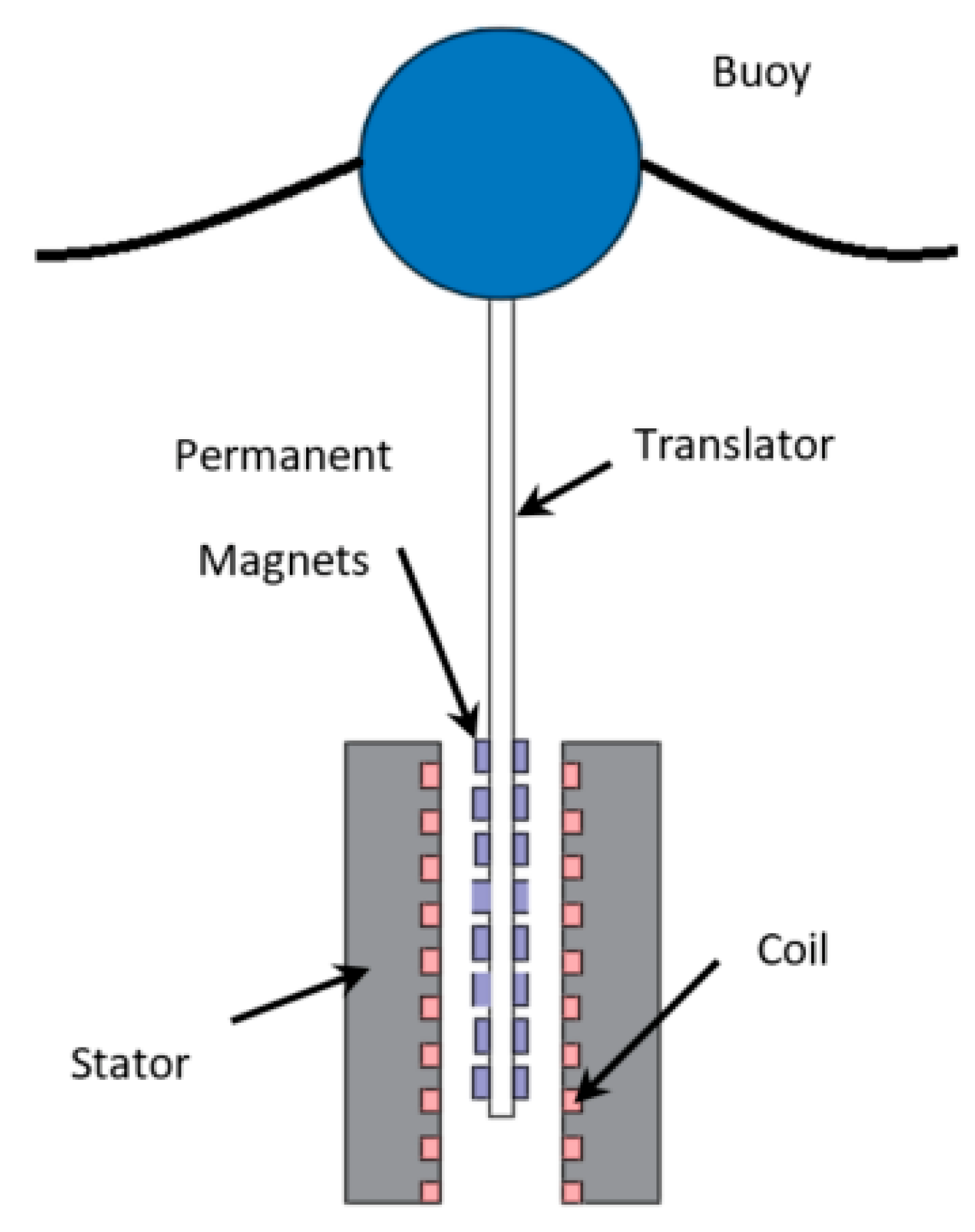
Figure 1. Schematic diagram of the linear PM generator-based WEC [18].
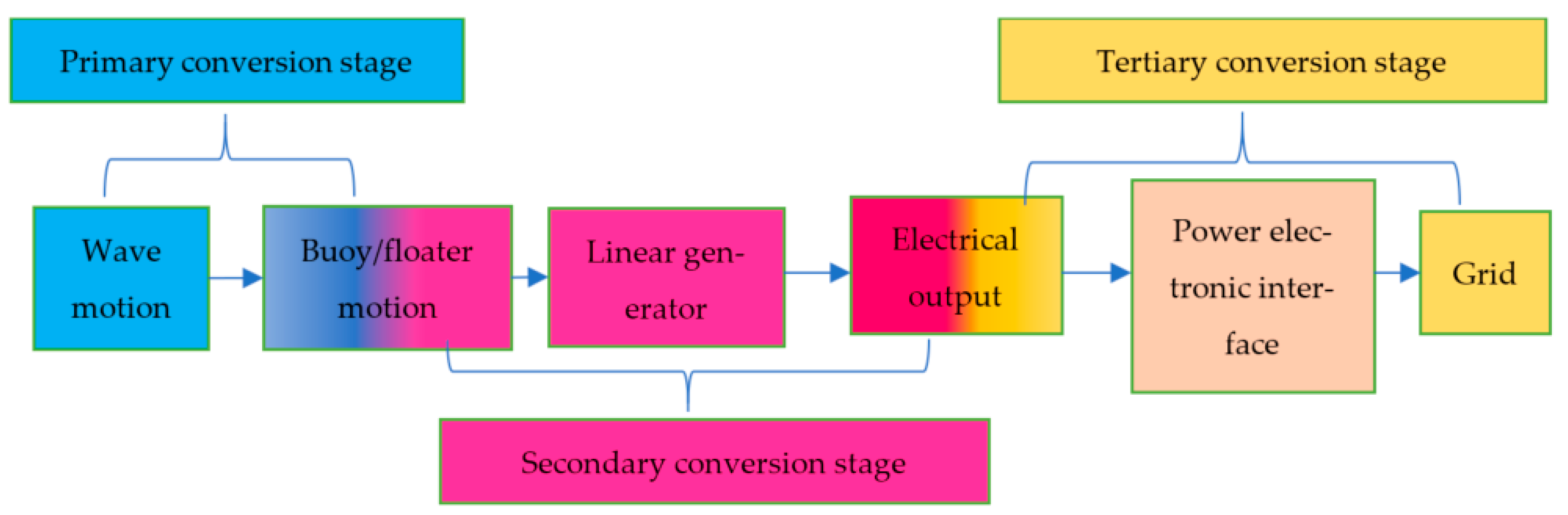
Figure 2. Basic functional units of a linear generator-based WEC.
The wave energy conversion system can be divided into the primary, secondary and tertiary conversion stages [19]. In the primary conversion stage, the WEC captures the wave’s kinetic energy through the buoy. The secondary conversion stage transforms the buoy motion energy into electricity via the linear generator. Finally, the tertiary conversion stage adapts the characteristics of the generated power with power electronic interfaces to the grid requirements.
2.1. Different Topologies of WECs with Linear Generator-Based PTO Systems
The main focus of this section is to provide an overall perspective on the various common types of linear wave generator configurations, presenting their advantages and disadvantages. The multiple topologies of WECs with linear PM PTO can be classified depending on the applications employed and the underlying system principles. Some systems are based on a floating buoy on the sea surface, as shown in Figure 3a, or a fully submerged heaving system, as displayed in Figure 3b. However, when the wave energy converter is fully submerged into the water, then it is less vulnerable to storms, but cooling problems and hydraulic and pneumatic intermediaries tend to cause failures, requiring higher maintenance costs. To avoid these construction, operational and maintenance difficulties, the best practice is not to submerge the device in the water [20].
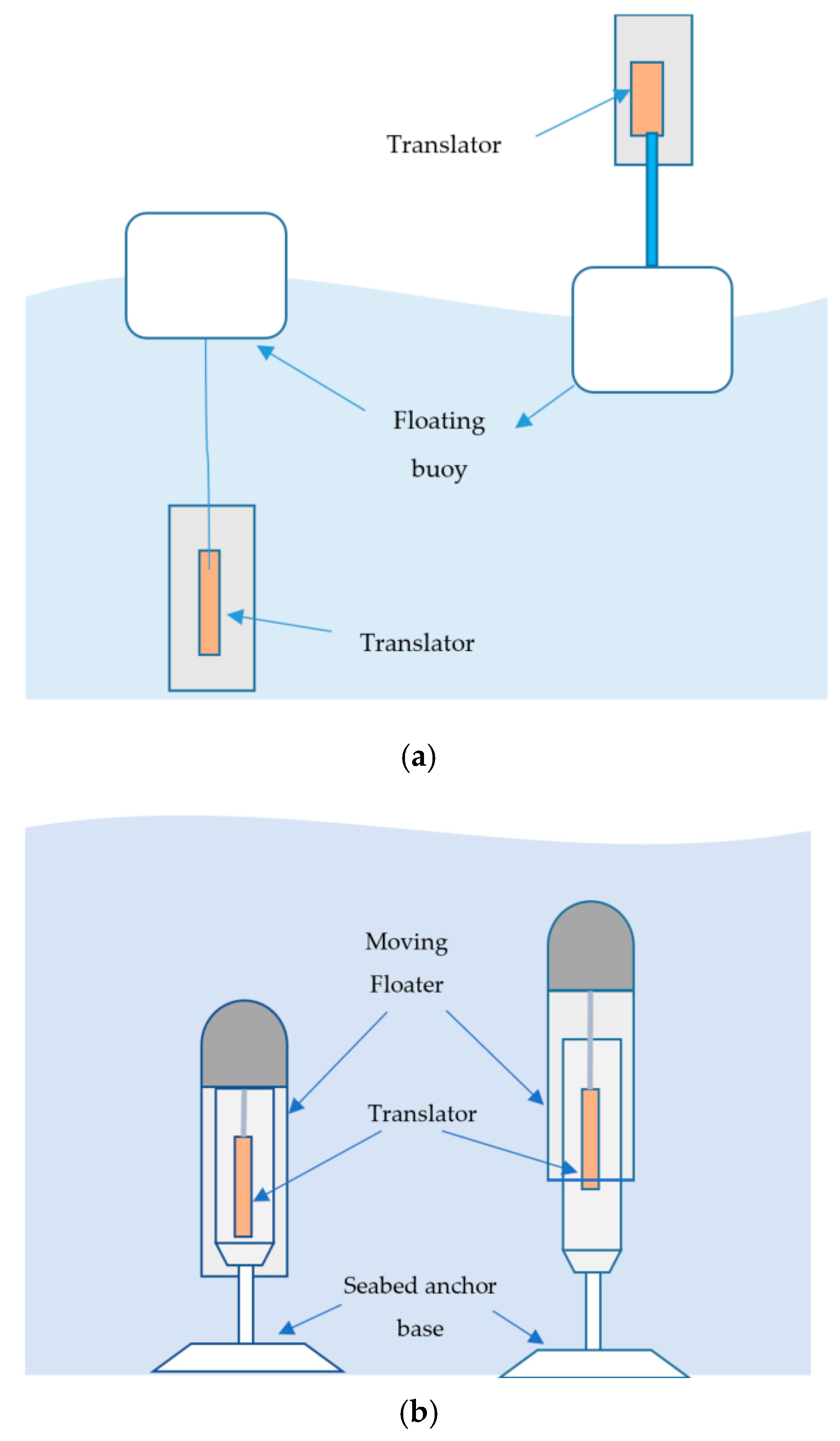
Figure 3. (a) Floating buoy on the sea surface (b) Fully submerged heaving system.
2.1.1. Floating Buoy on the Sea Surface
The most straightforward design using a floating buoy on the sea surface involves having the buoy directly connected to the generator moving part with a tether, while the linear generator is fixed onto the seabed [21]. Another possibility is placing the linear generator above the ocean surface, which is mounted with or without a fixed structure, and the translator of the generator is attached to the floating buoy [6][22]. The other common design concept is to leave the linear generator floating underneath the ocean surface and the translator directly connected with the floating buoy on the sea surface by a tether [23]. A new concept has been presented where the whole linear generator system floats on the sea surface [24]. Different direct-drive linear generator WECs have been developed based on these concepts. Still, the most appropriate technique might be to have the overall system partially above the sea surface because the submerged systems create difficulties, such as problems related to moorings, seawater corrosion and access for maintenance.
Single-Body Heaving Buoy System
The single-body heaving system is the most common in the research field of direct-drive linear wave energy converters because of its simplicity. The well-known direct-drive linear generator-based WECs developed at Uppsala University and Oregon University were based on the single-body heaving system [25]. Uppsala University’s developed WEC contained a buoy and linear generator, where the translator moved up and down with the buoy inside the linear generator system, which was fixed to the seabed. The rectangular-shaped translator had several permanent magnets, and the wound coils were connected with the stator [26]. Springs were also used to connect the translator with the linear generator foundation to retract the translator in the wave troughs [8]. The moving part of the linear generator is driven by the buoy’s motion and counteracted by a fixed component at the bottom sea spring. End stops were also used at the top and bottom of the device to restrict the translator’s stroke length during extreme oceanic conditions [8]. The linear generator designed by Oregon State University contained a spar and a float where the spar was moored, and the float moved up and down with the wave motion. The spar was a central cylindrical design housing a bobbin wound with a three-phase armature, and the float was an outside cylinder that consisted of 960 magnets. The float’s inner surface faced the spar’s outer surface, and when the float moved up and down due to the wave motion, the voltage was directly produced inside the armature [27]. The device was around 3.3 m high and 1.2 m wide, with 10 kW of rated power [28].
Two-Body Heaving Buoy System
The single-body heaving system poses several challenges, such as constructing a large enough device with a natural frequency that coincides with the incoming waves’ low frequency to achieve resonance. The distance between the floater and the seabed can be significant, and due to this enormous distance, the single-body heaving system has reduced efficiency. To solve these problems, some researchers proposed two-body heaving systems [29]. The two-body heaving system consists of either a floating section that deals directly with the wave and a fully submerged section or two floating sections [5]. The passive buoy or submerge section creates inertia for damping, and combining the floating body and submerge bodies helps the buoy follow the wave frequencies more closely. The linear generator can be mounted between the two bodies to avoid the large linear generator connection distance between the seabed and the free surface. Both bodies move due to the wave motion and create relative movement between them, causing both the translator and stator of the linear generator system to move, which helps to increase the efficiency. Elie Al Shami et al., reviewed the studies of single and two-body heaving systems with their dynamics, hydrodynamics, advantages and disadvantages [30].
The power capture ratio of the two-body heaving system’s converter has been reported as approximately 80% when the waves are irregular. If a 14-ton translator was used, the coupling between the linear generator, submerged body (passive buoy), and floating buoy on the sea surface became rigid. In addition, if the submerged body (passive buoy) was placed at a depth of 40 m, the achieved power capture ratio was around 80%. The power capture ratio decreased to about 50% when the depth decreased by 30 m. The resonance behaviour of the two-body heaving system significantly affects the linear generators’ efficiency.
Moreover, another novel topology has been developed, which may be categorized as a fully floating two-body heaving direct-drive linear generator WEC [5]. The proposed system consists of a spar fixed on the sea floor and a floating system with two parts. The permanent magnets are mounted in the inner body, and the windings coils are mounted in the outer body. Both outer and inner bodies freely move up and down along the spar, and, during the movement, the outer body acts as a floating buoy to harness the wave energy, while the inner body experiences a forced oscillation.
2.1.2. Fully Submerged Heaving System
The Archimedes Wave Swing (AWS) is a fully submerged direct-drive device and was the first WEC device to utilise the linear permanent magnet generator as the PTO system [9]. The linear generator of the device is attached to a compressed air chamber fixed on the seabed. The linear generator’s translator is connected with the fully submerged floater (underwater). The working principle of the AWS is based on the oscillating movement of the sea waves, which increases and decreases pressure levels successively under the sea surface because of the wave motion. Due to the wave motion, the floater moves vertically up and down with respect to the fixed lower part and increases the wave pressure levels, forcing the air inside the chamber to be compressed. The volume inside the chamber expands when the air pressure becomes larger than that of the wave [7]. This reciprocating linear motion generates electrical energy from the wave motion. However, the wholly submerged system has the same advantages and disadvantages as the AWS. These fully submerged systems are not visibly gaining public acceptance, though they are less vulnerable to severe ocean weather conditions. On the other hand, because of the ocean’s environmental conditions, it requires higher maintenance costs. Moreover, the corrosion of metals, and the disturbance of the marine life are two drawbacks of the fully submerged systems.
2.1.3. Other Topologies of WECs with Linear Generator-Based PTO Systems
Other than the floating buoy on the sea surface and fully submerged heaving systems, there are other topologies of WECs with linear PM generators, such as the fully floating gyroscopic system and buoyant system, which have been proposed and tested experimentally [31]. The fully floating gyroscopic-based WEC consists of gyroscope systems and linear permanent magnet generators inside a fully sealed buoy [31]. The gyroscope’s inertial reactions are applied to the device (inertial sea wave energy converter (ISWEC)) as a floating buoy slack-moored to the ocean floor. The stroke of the linear generator is short, and the reciprocating motion between the gyroscopic system and the hull is used to drive the linear electrical generators. On the other hand, the buoyant electrical generator-based WEC is a point absorber-type device that consists of a linear generator, boat-shaped buoy and an electronic power section [12]. The linear generator is placed inside the buoyant system. The proposed device is claimed to provide a highly reliable wave energy conversion system that can produce hydrogen to store energy. Another new topology of WEC with a linear PM generator has been proposed, known as a surface riding WEC, where the magnet assembly slides inside the armature [32].
2.2. Linear Permanent Magnet (PM) Generator Topologies
So far, different types of linear generators have been used for WECs, which include linear permanent magnet (PM) synchronous generators [33], flux-switching permanent magnet linear generators [34], switched reluctance linear generators [35], vernier hybrid machines [36], and so on. Due to the low-cost power electronic converter’s availability and the permanent magnet (PM) material’s improvements in terms of remnant flux density, coercive force, magnetic flux leakage and copper losses of field windings, and operating temperature, PM-based linear generators are suitable for energy harvesting across the broadband frequency ranges [37]. Moreover, the exerted force and power density can be increased by using permanent magnet excitation. Therefore, up to now, the vast majority of the linear generators for wave energy conversion have been developed based on synchronous permanent magnet generators because of their efficiency at low speeds, price and robustness [34]. The PM-based linear generator’s geometry plays a significant role in the design development; its variation substantially affects the overall performance and efficiency. In the literature, various PM linear generator topologies have been proposed for wave energy conversion systems, shown in Figure 4.
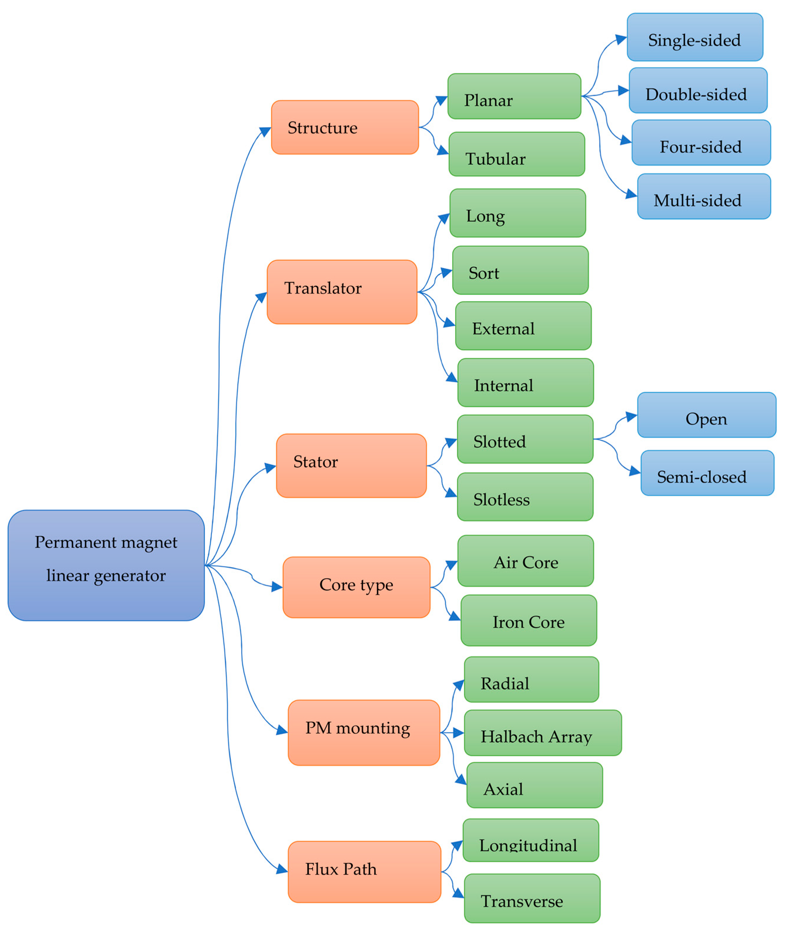
Figure 4. Linear PM generator topologies.
The main components of the linear PM generator are permanent magnets and coils. The linear PM generator topologies can be classified according to various design methods, such as structure, translator size and location, stator shape, core type, location of the permanent magnet (PM), flux path and the installation method of the PM. The structure of the linear PM generator may be tubular or planar/flat [38]. It is easier to fabricate the planar-type linear generator for WECs. It can be constructed with different sides, such as two-sided, four-sided, octagonal or multisided-planar generators [39]. A hybrid generator concept has also been proposed using the double-sided planar layout and tubular layout, which creates higher force density due to more effective use of space [40]. Different translator sizes and positions have been used in linear PM generators for direct-drive WECs. Due to the reciprocating linear motion, the translator or the stator must be longer to maintain the system’s generation operation for the stroke’s larger fraction. Typically, the permanent magnet translator is longer than the stator to keep the whole stator winding active during the entire stroke and reduce the amount of series copper and conduction losses [41]. Moreover, the translator can be mounted internally or externally on the generator design for the direct-drive WEC [42].
There are three possible ways to attach the permanent magnets: axially aligned-buried, radially aligned-buried and radially aligned-surface [40]. In addition to that, to get the maximum magnetic flux density Halbach, quasi-Halbach arrays have been used in linear PM generators for WECs [42]. The linear generators can be classified as transverse and longitudinal according to the location of windings relative to translator motion [17]. Using both transverse and longitudinal flux, a new hybrid transverse/longitudinal flux linear PM generator has been developed for WECs [43]. The device’s translator was sandwiched between two stators carrying flux in the longitudinal direction, while the translator carried flux in the transverse direction. Both slotless and slotted stators have been used in research to develop and find the best generator design [44]. The linear PM generator can be classified as an iron-core or air-core generator based on a core. Iron-core and air-core generators have been used in direct-drive PTO-based WECs [45]. All linear generator topologies’ advantages and drawbacks have been discussed briefly in [16]. Other than these topologies, some new, innovative design concepts have been proposed for capturing the maximum energy from ocean waves [46][47].
Innovative Oscillator Design Concept
To date, most of the linear PM generator PTO systems have been developed based on linear oscillator systems (single-degree-of-freedom oscillator system) and traditional design concepts (all permanent magnets are mounted in the translator, with opposite poles facing each other with an iron core used between them, and with coil windings attached in the stator). Usually, the translator moves inside the stator, creating magnetic flux changes inside the winding coils, which generate electrical energy. The linear energy-harvesting technology has been compared with nonlinear systems based on actual data, where it was found that the linear energy harvester has the highest power output in most cases. Still, the nonlinear system has a broader harvesting frequency bandwidth, and the bistable system can harness more energy from random vibration [48]. Moreover, Owens et al. also found that the nonlinear oscillating system is better than linear oscillation for broadening the frequency response bandwidth [49].
To create maximum magnetic flux density inside the coil, several permanent magnets could be added outside the stator coil, and this system is known as the bistable system [50]. It has been found that the proposed bistable system can increase the magnetic flux density inside the winding coils [51]. The linear generator converter’s resonant power and efficiency with light damping and multi-degree of freedom oscillators are expected to be larger than those with a conventional single-degree-of-freedom oscillator [46].
The bandwidth problem of the existing PM linear generator can be overcome by widening the frequency bandwidth of the WEC. Light-damping nonlinear oscillators are expected to have larger operational frequency bandwidths than a conventional single-degree-of-freedom linear oscillator. The magnetic levitation system can be used in the translator design to make the oscillator nonlinear, which is more effective in the broadband frequency range, especially in the low-frequency ocean environment [52]. In the magnetic levitation system, the magnetic spring works like a physical spring and is created when two magnets face each other at the same poles (N–N or S–S), as presented in Figure 5. In addition, the light-damping multi-degree-of-freedom nonlinear oscillators are expected to develop larger operational frequency bandwidths than a single-degree-of-freedom nonlinear oscillator.
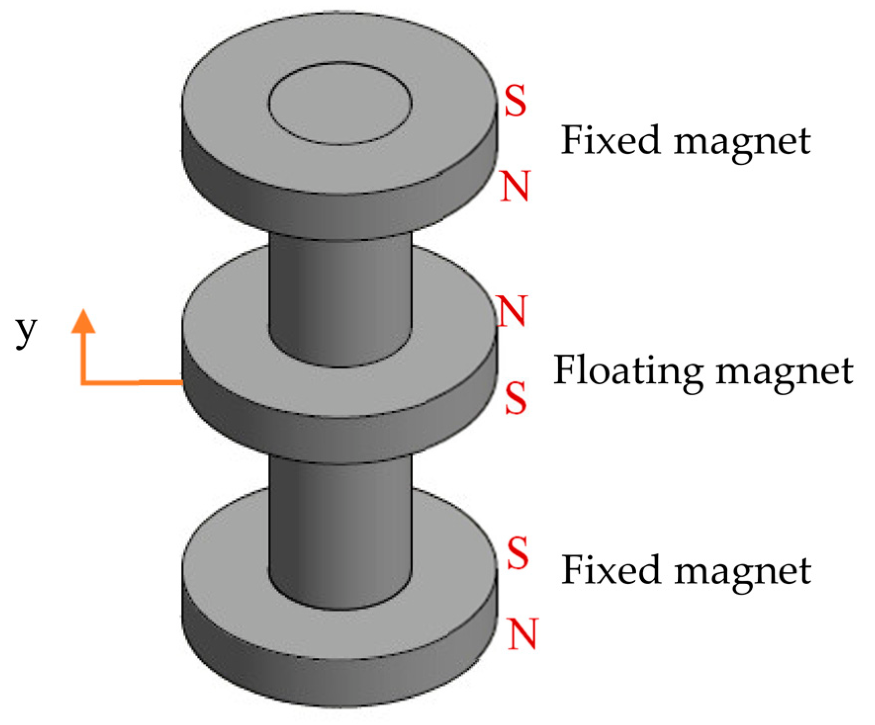
Figure 5. Schematic diagram of a single-degree-of-freedom nonlinear oscillator system.
References
- Ahamed, R.; McKee, K.; Howard, I. Advancements of wave energy converters based on power take off (PTO) systems: A review. Ocean Eng. 2020, 204, 107248.
- Day, A.; Babarit, A.; Fontaine, A.; He, Y.-P.; Kraskowski, M.; Murai, M.; Penesis, I.; Salvatore, F.; Shin, H.-K. Hydrodynamic modelling of marine renewable energy devices: A state of the art review. Ocean Eng. 2015, 108, 46–69.
- Xu, S.; Wang, S.; Soares, C.G. Review of mooring design for floating wave energy converters. Renew. Sustain. Energy Rev. 2019, 111, 595–621.
- Hong, Y.; Waters, R.; Boström, C.; Eriksson, M.; Engström, J.; Leijon, M. Review on electrical control strategies for wave energy converting systems. Renew. Sustain. Energy Rev. 2014, 31, 329–342.
- Gao, Y.; Shao, S.; Zou, H.; Tang, M.; Xu, H.; Tian, C. A fully floating system for a wave energy converter with direct-driven linear generator. Energy 2016, 95, 99–109.
- Zhang, J.; Yu, H.; Shi, Z. Design and Experiment Analysis of a Direct-Drive Wave Energy Converter with a Linear Generator. Energies 2018, 11, 735.
- Polinder, H.; Mecrow, B.C.; Jack, A.G.; Dickinson, P.G.; Mueller, M.A. Conventional and TFPM linear generators for direct-drive wave energy conversion. IEEE Trans. Energy Convers. 2005, 20, 260–267.
- Leijon, M.; Boström, C.; Danielsson, O.; Gustafsson, S.; Haikonen, K.; Langhamer, O.; Strömstedt, E.; Stålberg, M.; Sundberg, J.; Svensson, O. Wave energy from the North Sea: Experiences from the Lysekil research site. Surv. Geophys. 2008, 29, 221–240.
- Polinder, H.; Damen, M.; Gardner, F. Design, modelling and test results of the AWS PM linear generator. Eur. Trans. Electr. Power 2005, 15, 245–256.
- Chatzigiannakou, M.A.; Ulvgård, L.; Temiz, I.; Leijon, M. Offshore deployments of wave energy converters by Uppsala University, Sweden. Mar. Syst. Ocean Technol. 2019, 14, 67–74.
- Polinder, H.; Mueller, M.; Scuotto, M.; Goden de Sousa Prado, M. Linear generator systems for wave energy conversion. In Proceedings of the 7th European Wave and Tidal Energy Conference, Porto, Portugal, 11–13 September 2007; IDMEC-Institute de Engenharia Mecânica: Lisbon, Portugal, 2007.
- Trapanese, M.; Boscaino, V.; Cipriani, G.; Curto, D.; Di Dio, V.; Franzitta, V. A permanent magnet linear generator for the enhancement of the reliability of a wave energy conversion system. IEEE Trans. Ind. Electron. 2018, 66, 4934–4944.
- Saeed, O.; Wahyudie, A.; Susilo, T.B.; Shareef, H. Simple resonance circuit to improve electrical power conversion in a two-sided planar permanent magnet linear generator for wave energy converters. IEEE Access 2017, 5, 18654–18664.
- Mueller, M. Electrical generators for direct drive wave energy converters. IEE Proc.-Gener. Transm. Distrib. 2002, 149, 446–456.
- Faiz, J.; Nematsaberi, A. Linear electrical generator topologies for direct-drive marine wave energy conversion-an overview. IET Renew. Power Gener. 2017, 11, 1163–1176.
- Khatri, P.; Wang, X. Comprehensive review of a linear electrical generator for ocean wave energy conversion. IET Renew. Power Gener. 2019, 14, 949–958.
- Curto, D.; Viola, A.; Franzitta, V.; Trapanese, M.; Cardona, F. A New Solution for Sea Wave Energy Harvesting, the Proposal of an Ironless Linear Generator. J. Mar. Sci. Eng. 2020, 8, 93.
- Drew, B.; Plummer, A.R.; Sahinkaya, M.N. A review of wave energy converter technology. In Sage Publications; Sage UK: London, UK, 2009.
- Rusu, E.; Venugopal, V. Offshore Renewable Energy: Ocean Waves, Tides and Offshore Wind; MDPI: Basel, Switzerland, 2019.
- Rhinefrank, K.; Agamloh, E.; von Jouanne, A.; Wallace, A.; Prudell, J.; Kimble, K.; Aills, J.; Schmidt, E.; Chan, P.; Sweeny, B. Novel ocean energy permanent magnet linear generator buoy. Renew. Energy 2006, 31, 1279–1298.
- Hai, L.; Svensson, O.; Isberg, J.; Leijon, M. Modelling a point absorbing wave energy converter by the equivalent electric circuit theory: A feasibility study. J. Appl. Phys. 2015, 117, 164901.
- López, I.; Andreu, J.; Ceballos, S.; De Alegría, I.M.; Kortabarria, I. Review of wave energy technologies and the necessary power-equipment. Renew. Sustain. Energy Rev. 2013, 27, 413–434.
- Bastien, S.P.; Sepe, R.B.; Grilli, A.R.; Grilli, S.T.; Spaulding, M.L. Ocean wave energy harvesting buoy for sensors. In Proceedings of the IEEE Energy Conversion Congress and Exposition, San Jose, CA, USA, 20–24 September 2009; IEEE: Piscataway, NJ, USA, 2009; pp. 3718–3725.
- Panicker, P. The Vertical Axis Oscillating Wave Power Generator. Available online: https://contest.techbriefs.com/2012/entries/sustainable-technologies/2496 (accessed on 10 June 2022).
- Castellucci, V.; Eriksson, M.; Waters, R. Impact of tidal level variations on wave energy absorption at wave hub. Energies 2016, 9, 843.
- Waters, R.; Stålberg, M.; Danielsson, O.; Svensson, O.; Gustafsson, S.; Strömstedt, E.; Eriksson, M.; Sundberg, J.; Leijon, M. Experimental results from sea trials of an offshore wave energy system. Appl. Phys. Lett. 2007, 90, 034105.
- Prudell, J.; Stoddard, M.; Brekken, T.K.; von Jouanne, A. A novel permanent magnet tubular linear generator for ocean wave energy. In Proceedings of the Energy Conversion Congress and Exposition, ECCE 2009, San Jose, CA, USA, 20–24 September 2009; IEEE: Piscataway, NJ, USA, 2009; pp. 3641–3646.
- Brekken, T.K.; Von Jouanne, A.; Han, H.Y. Ocean wave energy overview and research at Oregon State University. In Proceedings of the Power Electronics and Machines in Wind Applications, 2009, PEMWA 2009, Lincoln, NE, USA, 24–26 June 2009; IEEE: Piscataway, NJ, USA, 2009; pp. 1–7.
- Amiri, A.; Panahi, R.; Radfar, S. Parametric study of two-body floating-point wave absorber. J. Mar. Sci. Appl. 2016, 15, 41–49.
- Al Shami, E.; Zhang, R.; Wang, X. Point absorber wave energy harvesters: A review of recent developments. Energies 2019, 12, 47.
- Boscaino, V.; Cipriani, G.; Di Dio, V.; Franzitta, V.; Trapanense, M. Experimental test and simulations on a linear generator-based prototype of a wave energy conversion system designed with a reliability-oriented approach. Sustainability 2017, 9, 98.
- Jin, C.; Kang, H.; Kim, M.; Bakti, F.P. Performance evaluation of surface riding wave energy converter with linear electric generator. Ocean Eng. 2020, 218, 108141.
- Seo, S.-W.; Shin, K.-H.; Koo, M.-M.; Hong, K.; Yoon, I.-J.; Choi, J.-Y. Experimentally Verifying the Generation Characteristics of a Double-Sided Linear Permanent Magnet Synchronous Generator for Ocean Wave Energy Conversion. IEEE Trans. Appl. Supercond. 2020, 30, 1–4.
- Huang, L.; Yu, H.; Hu, M.; Liu, C.; Yuan, B. Research on a tubular primary permanent-magnet linear generator for wave energy conversions. IEEE Trans. Magn. 2013, 49, 1917–1920.
- Di Dio, V.; Franzitta, V.; Milone, D.; Pitruzzella, S.; Trapanese, M.; Viola, A. Design of Bilateral Switched Reluctance Linear Generator to Convert Wave Energy: Case Study in Sicily; Advanced Materials Research; Trans Tech Publications: Zurich, Switzerland, 2014; pp. 1694–1698.
- Baker, N.J.; Raihan, M.A.; Almoraya, A.A. A cylindrical linear permanent magnet Vernier hybrid machine for wave energy. IEEE Trans. Energy Convers. 2018, 34, 691–700.
- Mueller, M.; Baker, N.; Ran, L.; Chong, N.; Wei, H.; Tavner, P.; McKeever, P. Experimental Tests of an Air-Cored PM Tubular Generator for Direct Drive Wave Energy Converters; IET: Auburn Hills, MI, USA, 2008.
- Wahyudie, A.; Jama, M.; Susilo, T.B.; Mon, B.F.; Shaaref, H.; Noura, H. Design and testing of a laboratory scale test rig for wave energy converters using a double-sided permanent magnet linear generator. IET Renew. Power Gener. 2017, 11, 922–930.
- Wahyudie, A.; Susilo, T.B.; Jama, M.; Mon, B.F.; Shaaref, H. Design of a Double-Sided Permanent Magnet Linear Generator for Laboratory Scale Ocean Wave Energy Converter; OCEANS 2017-Anchorage; IEEE: Piscataway, NJ, USA, 2017; pp. 1–5.
- Joseph, D.M.; Cronje, W.A. Design and analysis of a double-sided tubular linear synchronous generator with particular application to wave-energy conversion. In Proceedings of the 2007 IEEE Power Engineering Society Conference and Exposition in Africa-PowerAfrica, Johannesburg, South Africa, 16–20 July 2007; IEEE: Piscataway, NJ, USA, 2007; pp. 1–8.
- Prudell, J.; Stoddard, M.; Amon, E.; Brekken, T.K.; Von Jouanne, A. A permanent-magnet tubular linear generator for ocean wave energy conversion. IEEE Trans. Ind. Appl. 2010, 46, 2392–2400.
- Liu, C.; Yu, H.; Hu, M.; Liu, Q.; Zhou, S.; Huang, L. Research on a permanent magnet tubular linear generator for direct drive wave energy conversion. IET Renew. Power Gener. 2013, 8, 281–288.
- Vining, J.; Lipo, T.; Venkataramanan, G. Design and optimization of a novel hybrid transverse/longitudinal flux, wound-field linear machine for ocean wave energy conversion. In Proceedings of the 2009 IEEE Energy Conversion Congress and Exposition, San Jose, CA, USA, 20–24 September 2009; IEEE: Piscataway, NJ, USA, 2009; pp. 3726–3733.
- Tan, Y.; Lin, K.; Zu, J.W. Analytical modelling of Halbach linear generator incorporating pole shifting and piece-wise spring for ocean wave energy harvesting. AIP Adv. 2018, 8, 056615.
- Ran, L.; Mueller, M.; Ng, C.; Tavner, P.; Zhao, H.; Baker, N.; McDonald, S.; McKeever, P. Power conversion and control for a linear direct drive permanent magnet generator for wave energy. IET Renew. Power Gener. 2011, 5, 1–9.
- Wang, X. Frequency Analysis of Vibration Energy Harvesting Systems; Academic Press: Cambridge, MA, USA, 2016.
- Ahamed, R.; Howard, I.; McKee, K. Study of gravitational force effects, magnetic restoring forces and coefficients of the magnetic spring-based nonlinear oscillator system. IEEE Trans. Magn. 2022.
- Beeby, S.P.; Wang, L.; Zhu, D.; Weddell, A.S.; Merrett, G.V.; Stark, B.; Szarka, G.; Al-Hashimi, B.M. A comparison of power output from linear and nonlinear kinetic energy harvesters using real vibration data. Smart Mater. Struct. 2013, 22, 075022.
- Owens, B.A.; Mann, B.P. Linear and nonlinear electromagnetic coupling models in vibration-based energy harvesting. J. Sound Vib. 2012, 331, 922–937.
- Xiao, X.; Xiao, L.; Peng, T. Comparative study on power capture performance of oscillating-body wave energy converters with three novel power take-off systems. Renew. Energy 2017, 103, 94–105.
- Gao, M.; Wang, Y.; Wang, Y.; Wang, P. Experimental investigation of non-linear multi-stable electromagnetic-induction energy harvesting mechanism by magnetic levitation oscillation. Appl. Energy 2018, 220, 856–875.
- Masoumi, M.; Wang, Y. Repulsive magnetic levitation-based ocean wave energy harvester with variable resonance: Modeling, simulation and experiment. J. Sound Vib. 2016, 381, 192–205.
More
Information
Subjects:
Energy & Fuels; Engineering, Mechanical
Contributors
MDPI registered users' name will be linked to their SciProfiles pages. To register with us, please refer to https://encyclopedia.pub/register
:
View Times:
2.5K
Revisions:
2 times
(View History)
Update Date:
01 Sep 2022
Table of Contents


Notice
You are not a member of the advisory board for this topic. If you want to update advisory board member profile, please contact office@encyclopedia.pub.
OK
Confirm
Only members of the Encyclopedia advisory board for this topic are allowed to note entries. Would you like to become an advisory board member of the Encyclopedia?
Yes
No
${ textCharacter }/${ maxCharacter }
Submit
Cancel
Back
Comments
${ item }
|
${ item.createdUser.fullName }
${ item.createdAt }
${ item.vote }
${ item.reply }
Delete
${ reply.createdUser.fullName }
${ reply.createdAt }
${ reply.vote }
Delete
There is no reply to this comment~
${ item.replyTextCharacter }/${ item.replyMaxCharacter }
Submit
Cancel
More
No more~
There is no comment~
${ textCharacter }/${ maxCharacter }
Submit
Cancel
${ selectedItem.replyTextCharacter }/${ selectedItem.replyMaxCharacter }
Submit
Cancel
Confirm
Are you sure to Delete?
Yes
No