Your browser does not fully support modern features. Please upgrade for a smoother experience.
Submitted Successfully!
 +1 credit
Thank you for your contribution! You can also upload a video entry or images related to this topic.
For video creation, please contact our Academic Video Service.
| Version | Summary | Created by | Modification | Content Size | Created at | Operation |
|---|---|---|---|---|---|---|
| 1 | Shahid Jaman | -- | 1979 | 2022-08-15 12:44:29 | | | |
| 2 | Dean Liu | Meta information modification | 1979 | 2022-08-16 02:53:12 | | | | |
| 3 | Dean Liu | Meta information modification | 1979 | 2022-08-17 03:30:51 | | |
Video Upload Options
We provide professional Academic Video Service to translate complex research into visually appealing presentations. Would you like to try it?
Cite
If you have any further questions, please contact Encyclopedia Editorial Office.
Jaman, S.; Chakraborty, S.; Tran, D.; Geury, T.; Baghdadi, M.E.; Hegazy, O. Integrated On-Board Charger-Traction Systems. Encyclopedia. Available online: https://encyclopedia.pub/entry/26147 (accessed on 23 July 2026).
Jaman S, Chakraborty S, Tran D, Geury T, Baghdadi ME, Hegazy O. Integrated On-Board Charger-Traction Systems. Encyclopedia. Available at: https://encyclopedia.pub/entry/26147. Accessed July 23, 2026.
Jaman, Shahid, Sajib Chakraborty, Dai-Duong Tran, Thomas Geury, Mohamed El Baghdadi, Omar Hegazy. "Integrated On-Board Charger-Traction Systems" Encyclopedia, https://encyclopedia.pub/entry/26147 (accessed July 23, 2026).
Jaman, S., Chakraborty, S., Tran, D., Geury, T., Baghdadi, M.E., & Hegazy, O. (2022, August 15). Integrated On-Board Charger-Traction Systems. In Encyclopedia. https://encyclopedia.pub/entry/26147
Jaman, Shahid, et al. "Integrated On-Board Charger-Traction Systems." Encyclopedia. Web. 15 August, 2022.
Copy Citation
The Integrated On-board Charger (iOBC) is the innovative technique to design the on-board charging system in which the motor coil and traction inverter is used during charging as grid filter and active front-end power factor correction unit respectively. This technique helps to increase charging power density, reduce vehicle size and weight.
bidirectional EV charger
integrated on-board battery chargers (iOBCs)
charging control
1. Introduction
Electric vehicles (EVs) are the most competitive and promising transportation solution compared to internal combustion engine (ICE) vehicles due to their impact on carbon neutrality and resource efficiency [1]. To achieve ambitious EU Green deal targets, automotive Original Equipment Manufacturers (OEMs) aim to sell 100% of zero-emission cars from 2030 onwards [2][3]. According to the Global EV outlook 2021, the global EV market for all types of car sales was significantly affected by the economic repercussions of the COVID-19 pandemic. One-third of new car registrations dropped in the first part of 2020 when compared to the preceding year [4]. Though overall new car registration was falling, global EV car sales increased by up to 70% as 3 million new EV cars were registered in 2020, which was a record 4.6% annual growth. For the first time, Europe led with 1.4 million new registrations. China followed with 1.2 million registrations, while the number of new registration in the United States was 295,000 [4], as shown in Figure 1. Two aspects are essential to sustain exponential EV growth and sales demand. First, developing chargers and the availability of fast charging options need to be confirmed. Second, the bidirectionality, performance, and lifetime of the existing charger topologies must improve so that EV charging becomes more affordable and reliable [5].
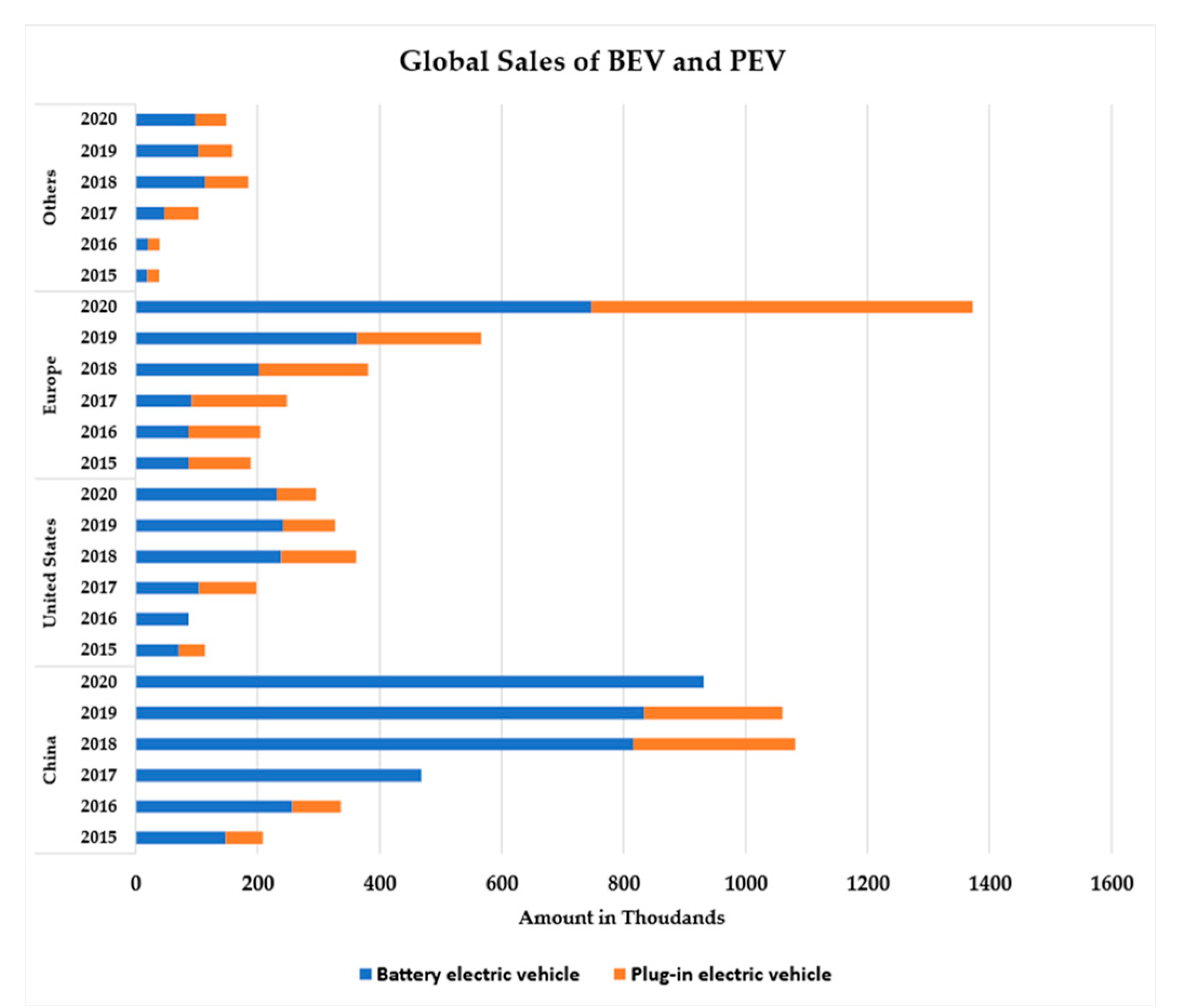
Figure 1. Electric vehicle sales (in thousands) in 2015–2020 (blue is used for BEV and orange for PEV) [4].
Two types of chargers are widely used for EV charging, i.e., on-board chargers (OBC) and off-board chargers. OEMs are still facing problems in the OBC as they are still expensive, bulky, and offer only unidirectional power flow (e.g., grid-to-vehicle (G2V)) [6][7]. To obtain higher power density, OEMs have headed towards integrated bidirectional OBC that could offer a more efficient and power-dense solution. Thus, due to the bidirectional features of OBCs, vehicle-to-grid (V2G) functionality can be achieved, which can transfer electrical energy back to the grid during peak demand [8].
Moreover, bidirectional features allow more functionalities in OBCs, such as vehicle-to-home (V2H), vehicle-to-device (V2D), or vehicle-to-vehicle (V2V), which leads to an increase in the power transfer capability [9]. However, power transfer capability is typically limited due to several constraints/tradeoffs such as cost, volume, and weight of the vehicle [10]. The iOBCs can help to overcome these limitations, as iOBCs build a closer integration of the motor and power electronics components (i.e., electric motor and traction inverter) for charging instead of using separate power electronics stages (e.g., AC/DC and DC/DC) and bulky inductors, as shown in Figure 2.
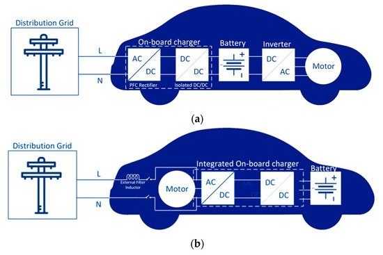
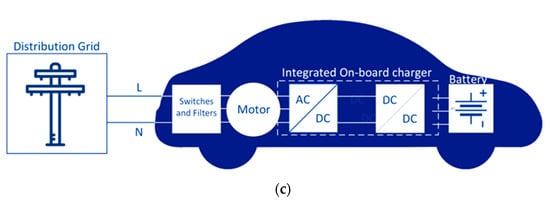
Figure 2. On-board power electronic interfaces for EV Charging.
2. Integrated On-Board Charger (iOBC) Topologies
The iOBCs can be classified into isolated and non-isolated, as illustrates in Figure 3. Most non-isolated iOBCs use AC line as an input, using the motor winding. Each leg of the traction inverter is connected to each phase of motor winding. Thus, the inverter can be used as an active front-end (AFE) rectifier during charging. The non-isolated iOBC can also be built using a three phase and multiphase machine. Single three phase motor based iOBCs have been investigated in [11][12][13]. In these works, two operations (charging and traction) have been tested.
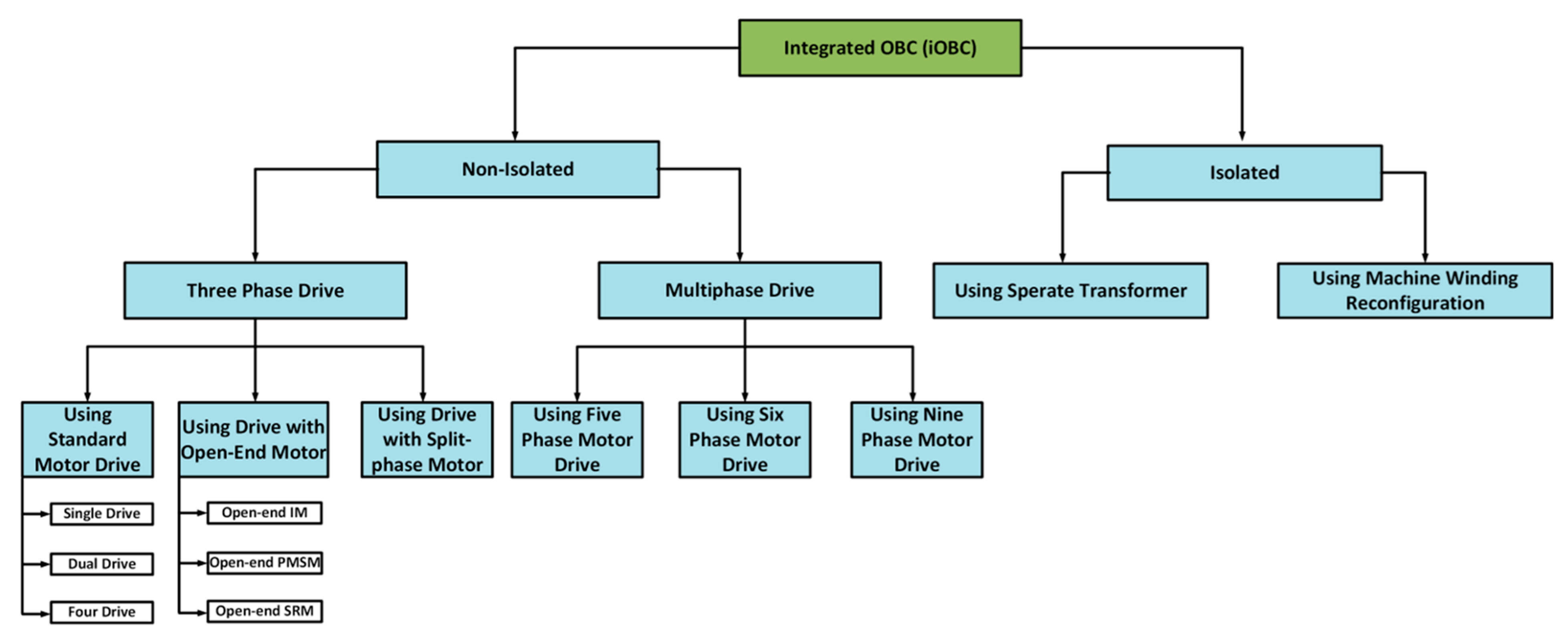
Figure 3. OBC integrated PE converter system topology classification.
These topologies use a contactor switch as shown in Figure 4 to connect the grid supply to the neutral point of the machine winding [14]. The stator winding can be utilized as a grid side filter. The motor uses symbols R and Lf as stator resistance and inductance, respectively. The main drawback of this topology is the current stress on the one leg, which is three times higher than on the other converter legs. Another single-phase charging solution with two IMs and two sets of dedicated converters is described in [15] (see Figure 5). The power from the battery is transferred to both motors, hence the driving torque is shared by them. An improved interleaving switching based integrated charger based on a two-motor drive was introduced in [16]. Two slow recovery diodes, D1 and D2, are added to alleviate the CM noise. As each diode provides a low-frequency path for the input current, the system ground is connected to the input terminal. Additional boost inductors, L1 and L2, are utilized for the purpose of compensating for the small CM inductance. This technique effectively improves the efficiency and current waveforms concurrently. Four motor iOBCs are also suitable for single phase supply, described in [17][18]. For the mode to take place it is necessary to disconnect the positive terminal of the battery from the dc-bus and to connect it to two isolated neutral points of two machines, as shown in Figure 6.
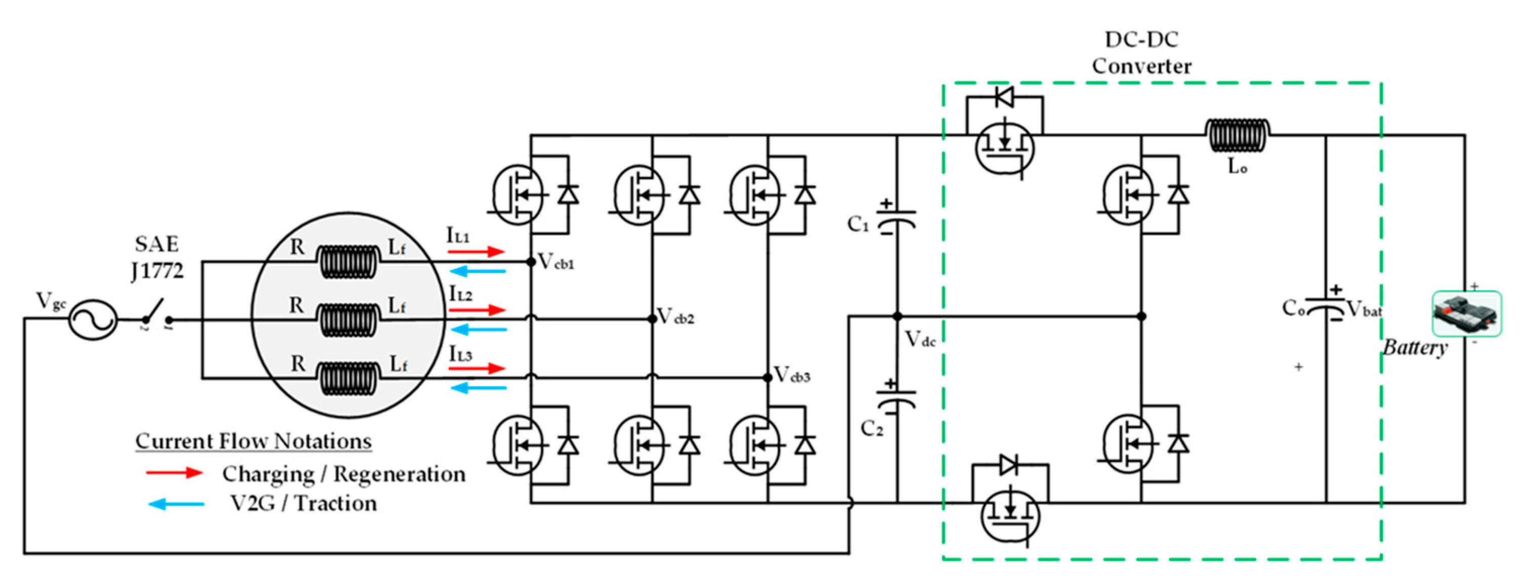
Figure 4. Single motor drive integrated on-board charger proposed by Gupta et al. [14] in 2020 (iOBC1).
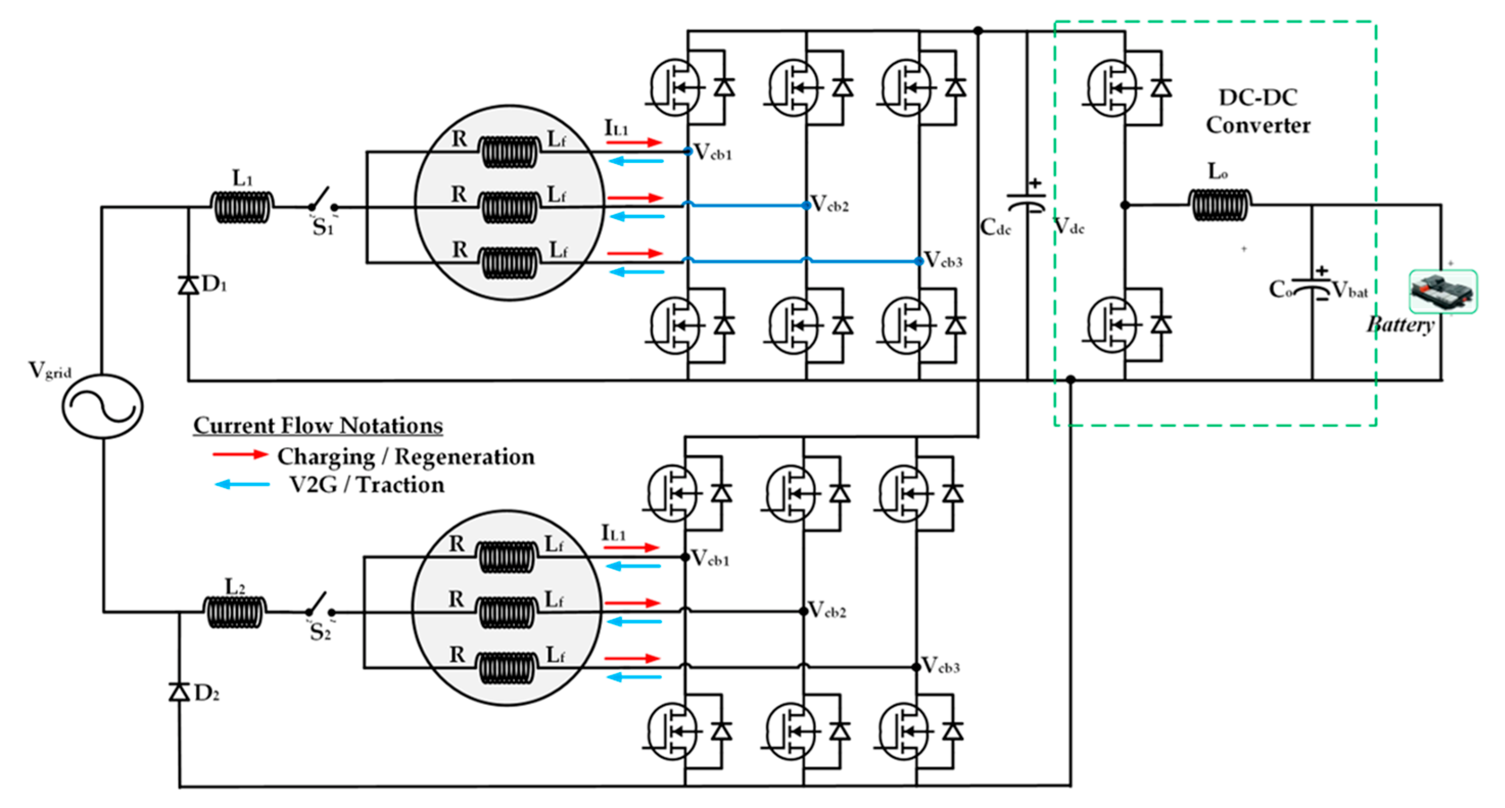
Figure 5. Dual motor drive integrated on-board charger proposed by Woo et al. [15] in 2015 (iOBC2).
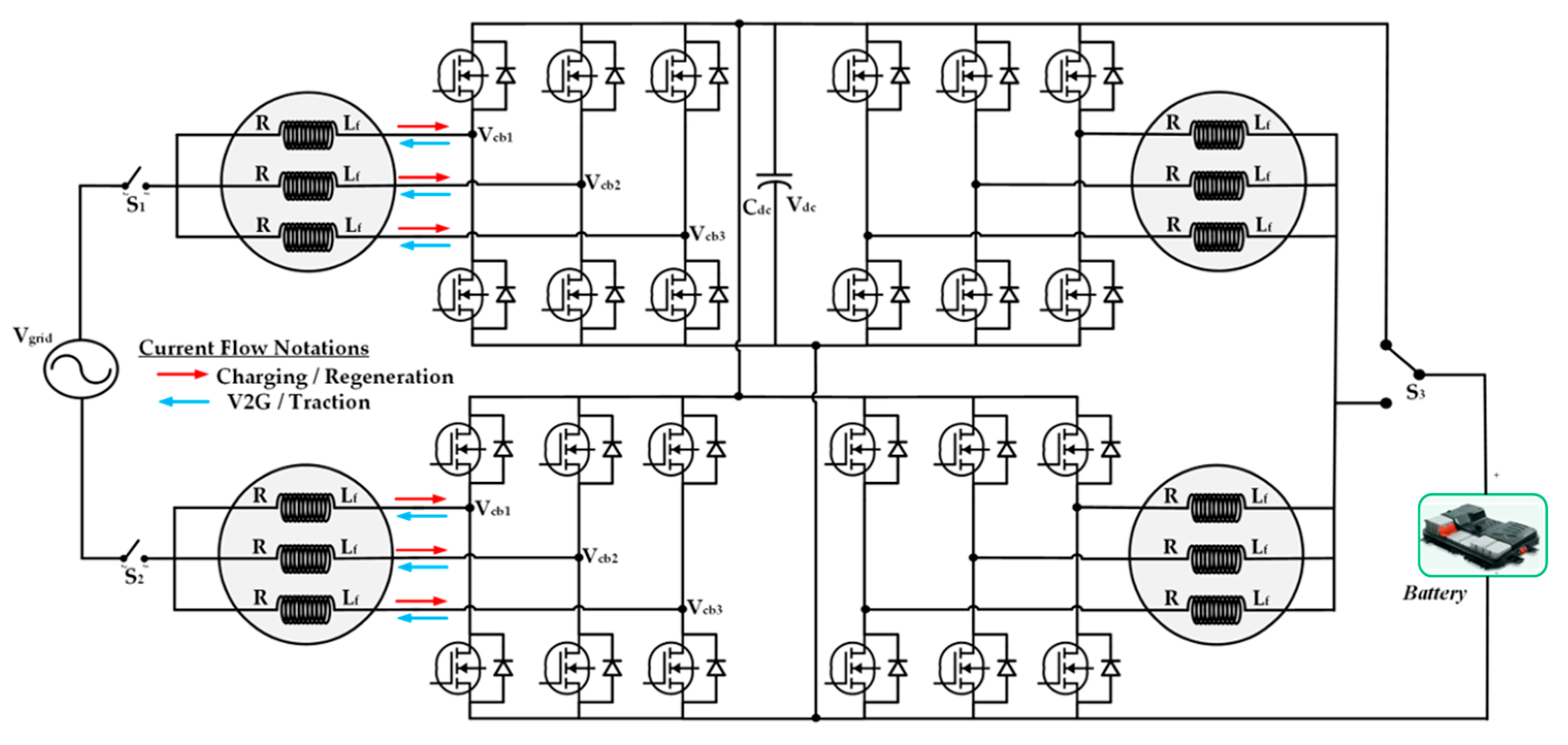
Figure 6. Four motor drive integrated on−board charger proposed by Subotic et al. [17] in 2014 (iOBC3).
A single-phase traction inverter integrated OBC is proposed in [19] (see Figure 7). For the charging mode from a single-phase grid, the traction inverter is configured as full bridge rectifier and inverter boost converter, using switches’ S1 to S5 configuration to connect the battery. This topology has a very simple structure and control, V2G features and small size.
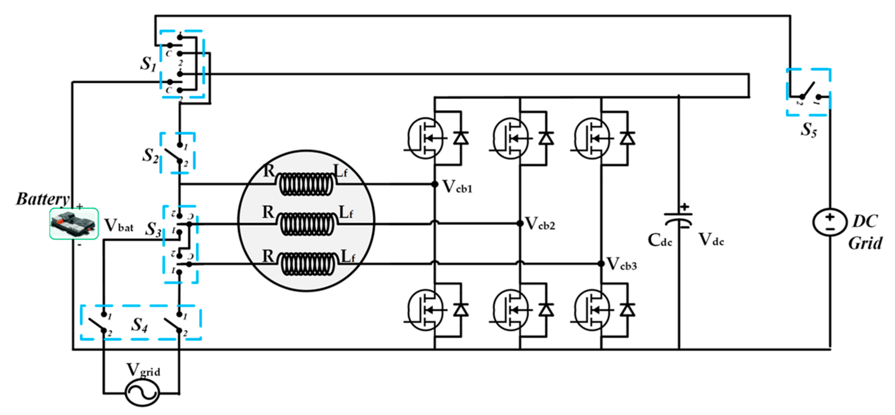
Figure 7. Induction motor drive integrated on−board charger with motor winding reconfiguration proposed by Khan et al. [19] in 2012 (iOBC4).
A PMSM drive integrated charging system has been introduced in [20] for electric motorcycle application. A rectifier and line filter used as an extra component in this system is depicted in Figure 8. A four-phase synchronous reluctance motor (SRM) winding is utilized in the iOBC system described in [21], as shown in Figure 9. This topology used one bridge of the inverter as a buck-boost converter and the other two bridges as a rectifier. The V2G and G2V functionalities of SRM drive iOBC have been explained in [22]. At first, two converter phases are utilized as a rectifier, with machine windings being employed as input filters. Then, when the grid voltage is rectified, the third phase acts as a dc-dc buck-boost converter to adjust the voltage to a value required by the battery. The fourth phase is not used during the charging process. To reduce switching losses, switch S4 is set permanently. There is no separate DC-DC converter for charging the battery in this topology, which gives simple reconstruction flexibility. Thus, the cost and size of the charger system decrease.
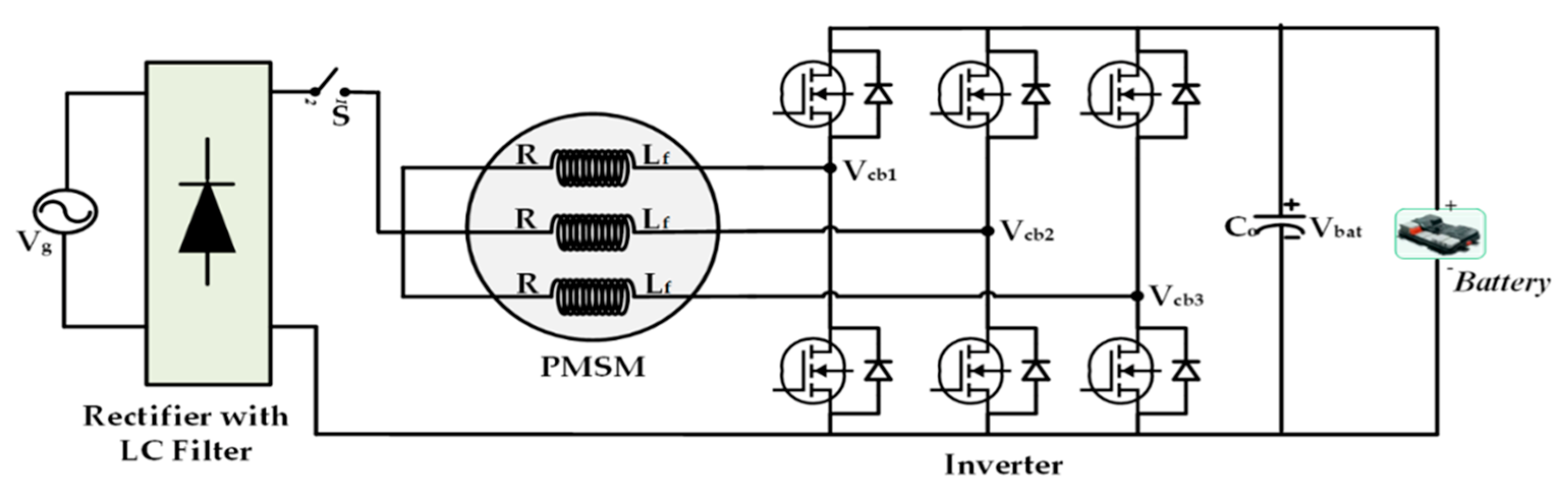
Figure 8. PMSM drive integrated on−board charger with neutral point access proposed by Tuan et al. [20] in 2021 (iOBC5).
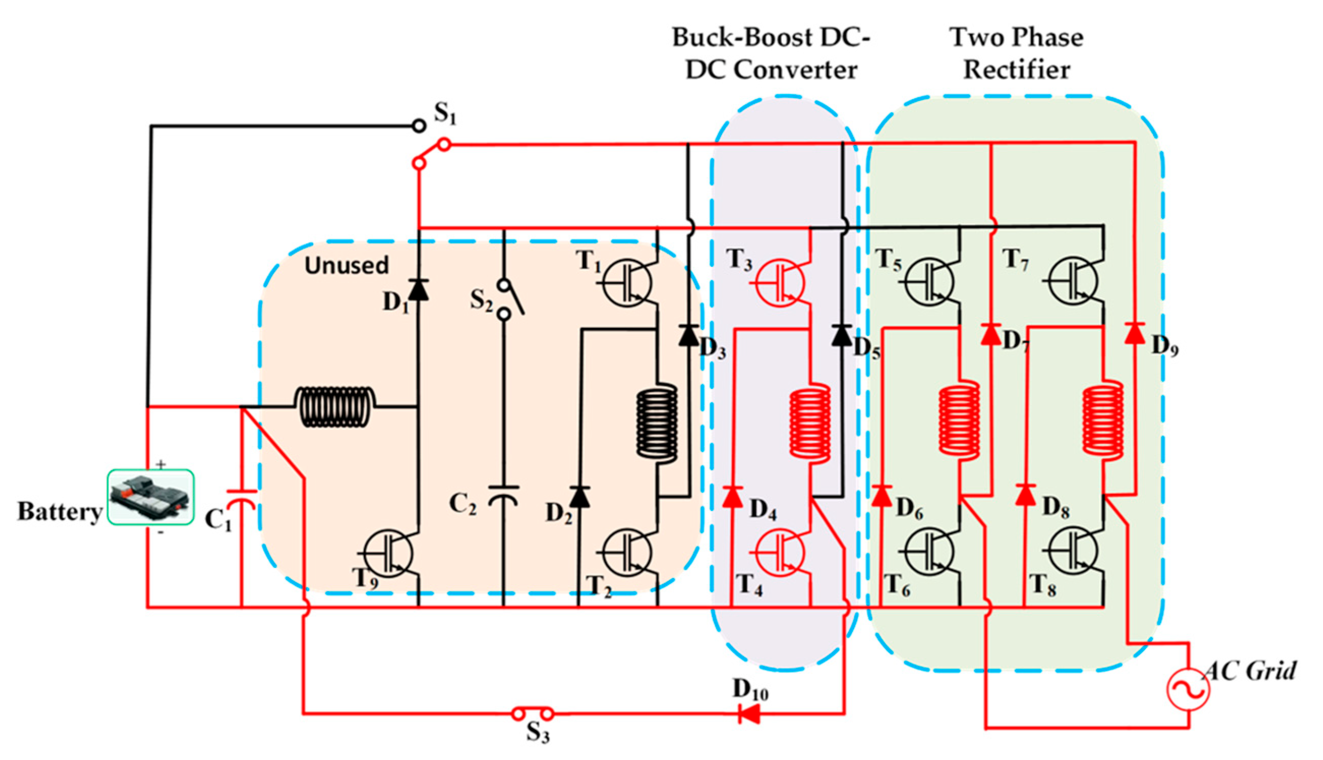
Figure 9. SRM drive integrated on−board charger proposed by Khayam Huseini et al. [21] in 2015. (iOBC6). The charging mode configuration is highlighted in red.
A cost effective 3-ph on-board charging system with interfaced converter is depicted in [23] and shown in Figure 10. The specific role of the interfaced converter in this topology is to configure the system during operating mode. Due to its simplicity, it allows high-power charging with comparatively less size and weight. An additional three-phase interface converter is used to avoid hardware reconfiguration. A fast three-phase charging system based on a split phase machine has been described in [24][25][26][27][28] and is shown in Figure 11. The mid-point of three phase winding is connected to the grid through an EMI filter and a H-bridge front-end converter with a battery connected to the machine. The main disadvantages of this topology are stator leakage inductance due to employed distributed winding, and complexity in control. An integrated on-board charger with open-end stator winding (OEW) configurations of three-phase IM is described in [29][30].
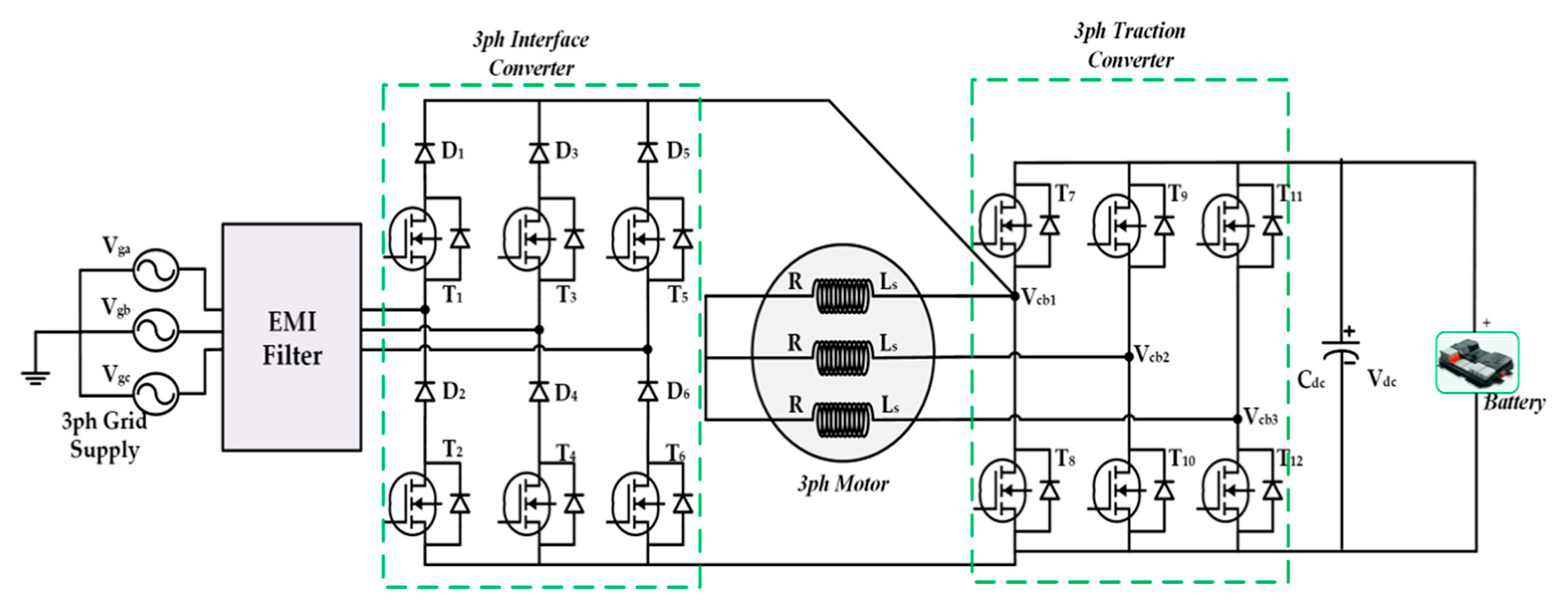
Figure 10. Three Phase integrated on−board charger with interface converter proposed by Shi et al. [23] in 2018. (iOBC7).
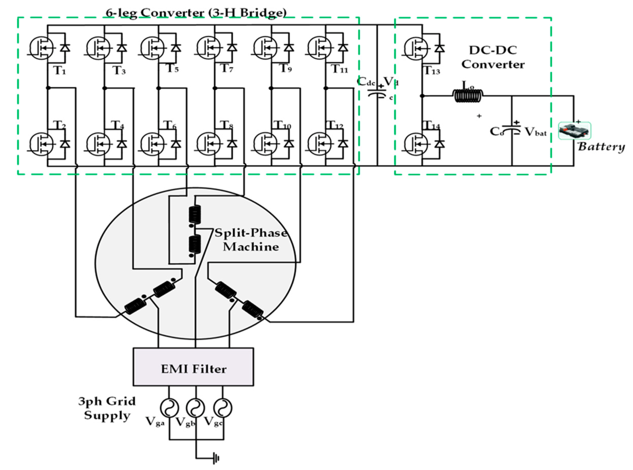
Figure 11. Three Phase Split-Phase Motor integrated on−board charger proposed by Hagbin et al [27] in 2014 (iOBC8).
The stator winding reconfiguration of these topologies can be carried out by using a switch as shown in Figure 12. Recently, Hyundai published a patent for a multi-charging system which is used in the Hyundai IONIQ 5 model, based on a OEW machine [31]. Another similar approach with asymmetrical hybrid multilevel converter as described in [32]. The OEW machine was also utilized to implement a dual drive integrated charger in [33][34].
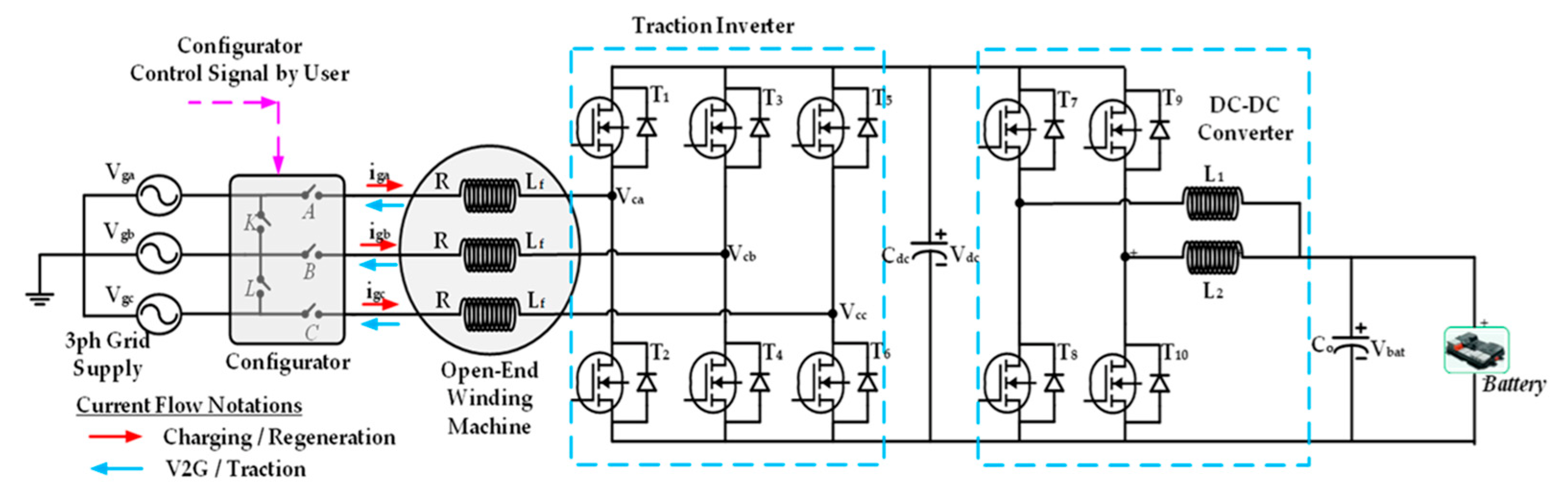
Figure 12. Integrated On−Board Charger based on Open-End Winding Machine proposed by Brull et al. [29] in 2016 (iOBC9).
Recently, segmented winding based three phase induction machines have caught researcher’s attention. This type of multi-winding machine is derived from the traditional three-phase machine, using the same number of stator slots and rotor poles. Various segmented three-phase machines have been reported in the literature, including the three-phase six-winding machine as shown in Figure 13 reported in [35][36], and the three-phase nine-winding machine depicted in Figure 14 and described in [37][38]. Multiphase machines have more than three phases; typically five, six and nine. They are categorized in two types as symmetrical and asymmetrical machines based on the spatial angle of two consecutive machine phases. They can have one or multiple isolated neutral points. The nine phase machines have higher torque and lower copper loss then six phase machines. The nine phase machine based iOBC topologies are investigated in [39][40].
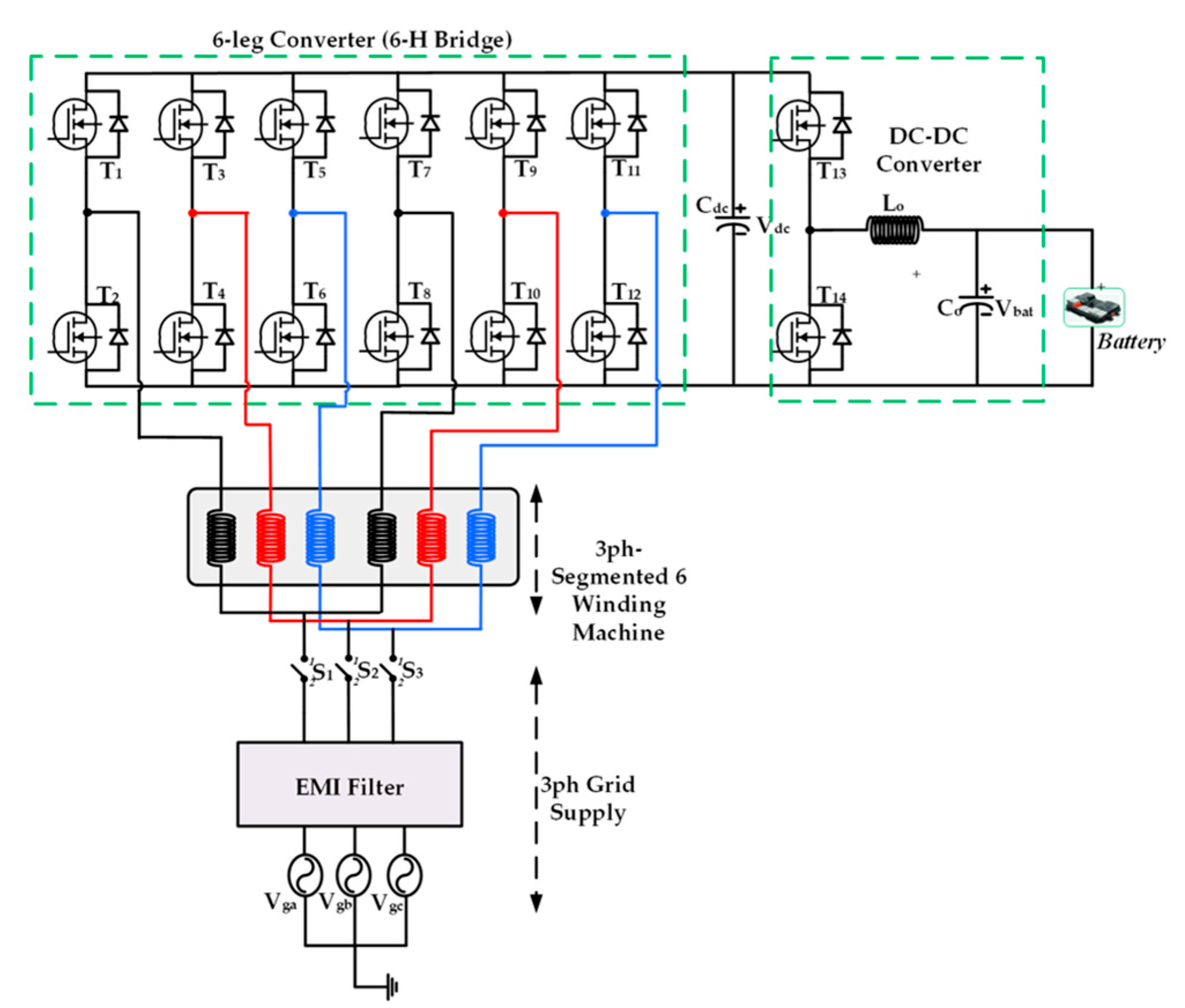
Figure 13. Integrated On−Board Charger based on 3-Phase 6-Segmented Winding Machine proposed by Han et al. [36] in 2018. (iOBC10).
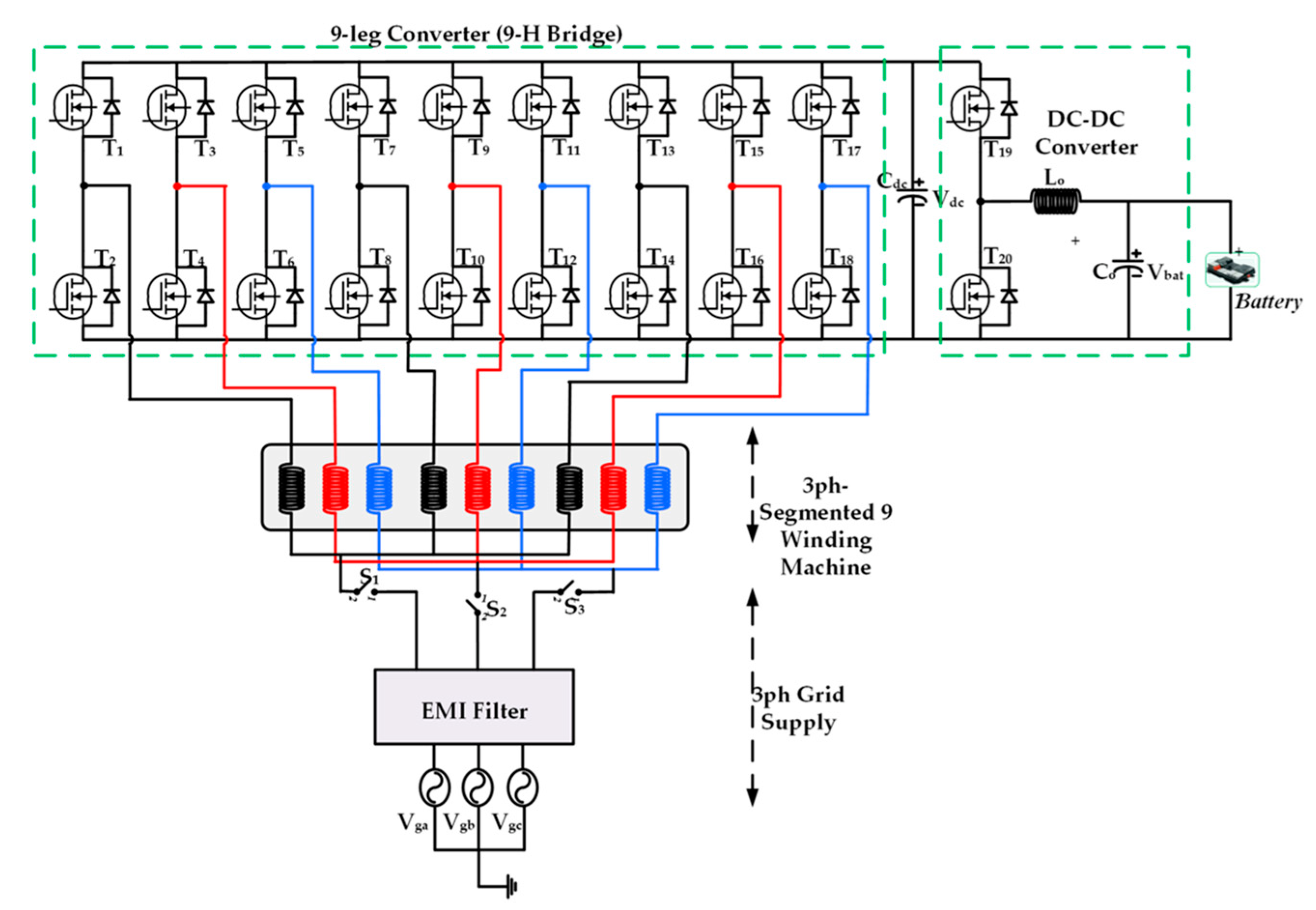
Figure 14. Integrated On−Board Charger based on 3-Phase 9-Segmented Winding Machine proposed by Raherimihaja et al. [37] in 2018 (iOBC11).
Since these topologies have a higher phase inverter as shown in Figure 15, a significant drawback of these converters is the relatively higher number of semiconductor switches and the complexity of the corresponding driving circuit. An impressive solution was introduced in [41] to reduce the number of switches.
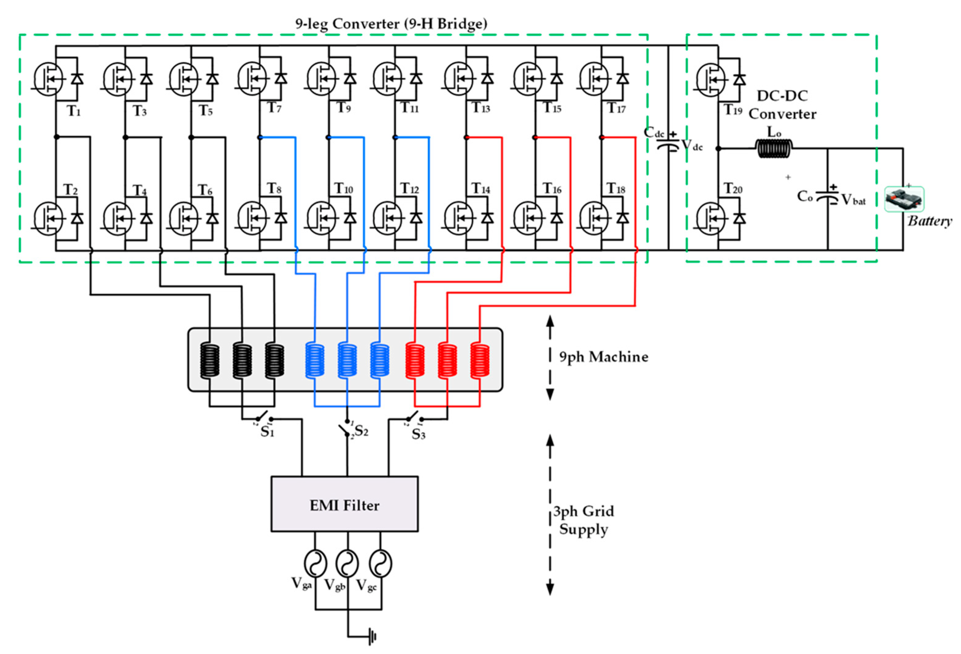
Figure 15. Integrated On−Board Charger based on Nine Phase Winding Machine proposed by Abdel-Khalik et al. [38] in 2017 (iOBC12).
The nine-switch converter was utilized with six phase machines as shown in Figure 16, where the stator coils act as filter during charging. The advantages of this topology are zero torque production during charging, the power factor is unity at the grid side and no phase transposition is needed. Additionally, only three additional switches are needed for changing the mode. The most challenging drawback is the utilization of low dc-link capacitance.
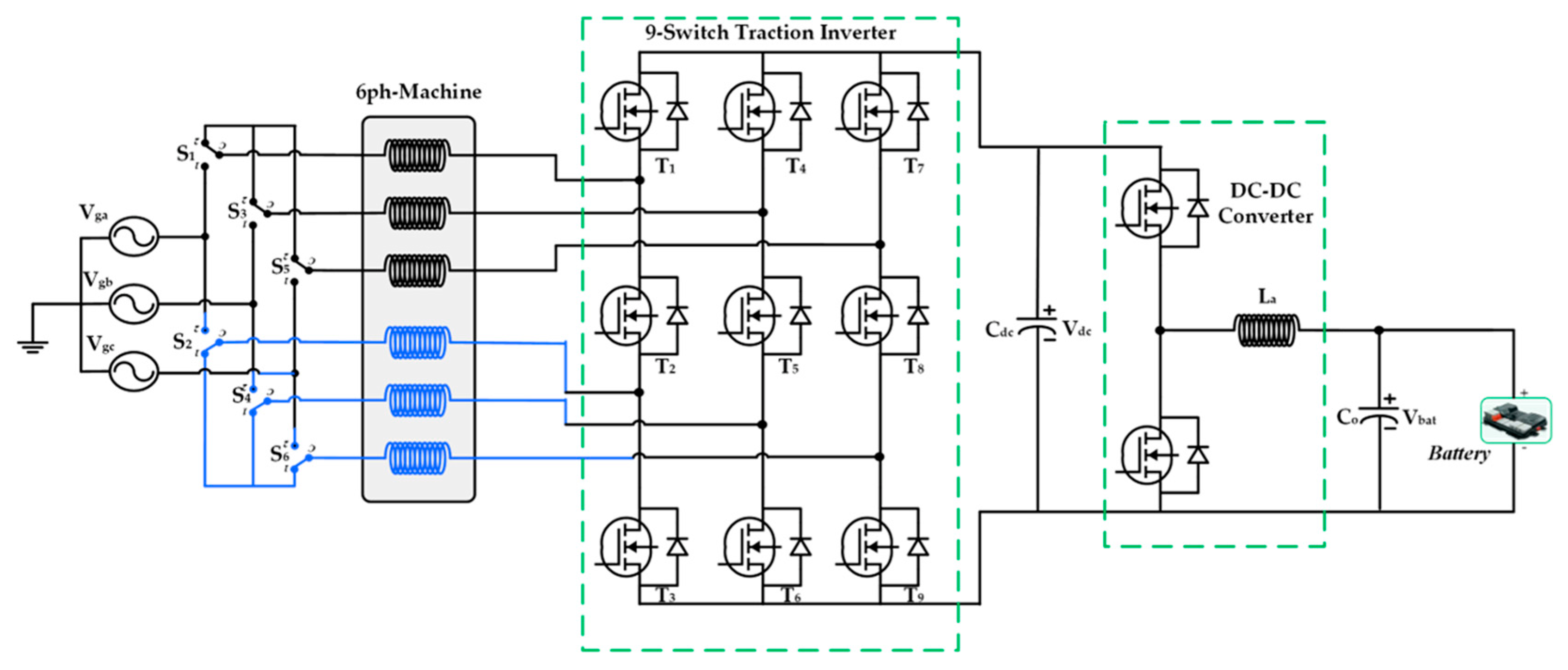
Figure 16. Integrated On−Board Charger based on Nine Phase Six Phase Winding Machine proposed by Diab et al. [41] in 2016. (iOBC13).
A five-phase machine approach (non-isolated method) as shown in Figure 17 is described in [42][43][44]. An efficiency analysis of the various integrated charger topologies shows that a nine-phase charger corresponds to the highest efficiency (reaching 86% during the charging mode). During charging, the efficiency varies from 79% to 86% based on the applied topology, while the efficiencies are slightly higher, between 81% and 89%, during the V2G mode. On the other hand, the isolated iOBCs can be implemented in two methods. One method can provide galvanic isolation by an additional transformer placed on the low-frequency AC side, as in [45]. Otherwise, the electrical isolation can be performed by reconfiguring the connections of the electrical machine to make it act as a transformer, which is proposed in [46][47], with six-phase and a nine-phase machines, respectively. In [48], a six-phase machine is used as transformer as shown in Figure 17 and provides galvanic isolation in both three- and single-phase input operation, with the peculiarity of achieving torque-free charging in single-phase configuration.
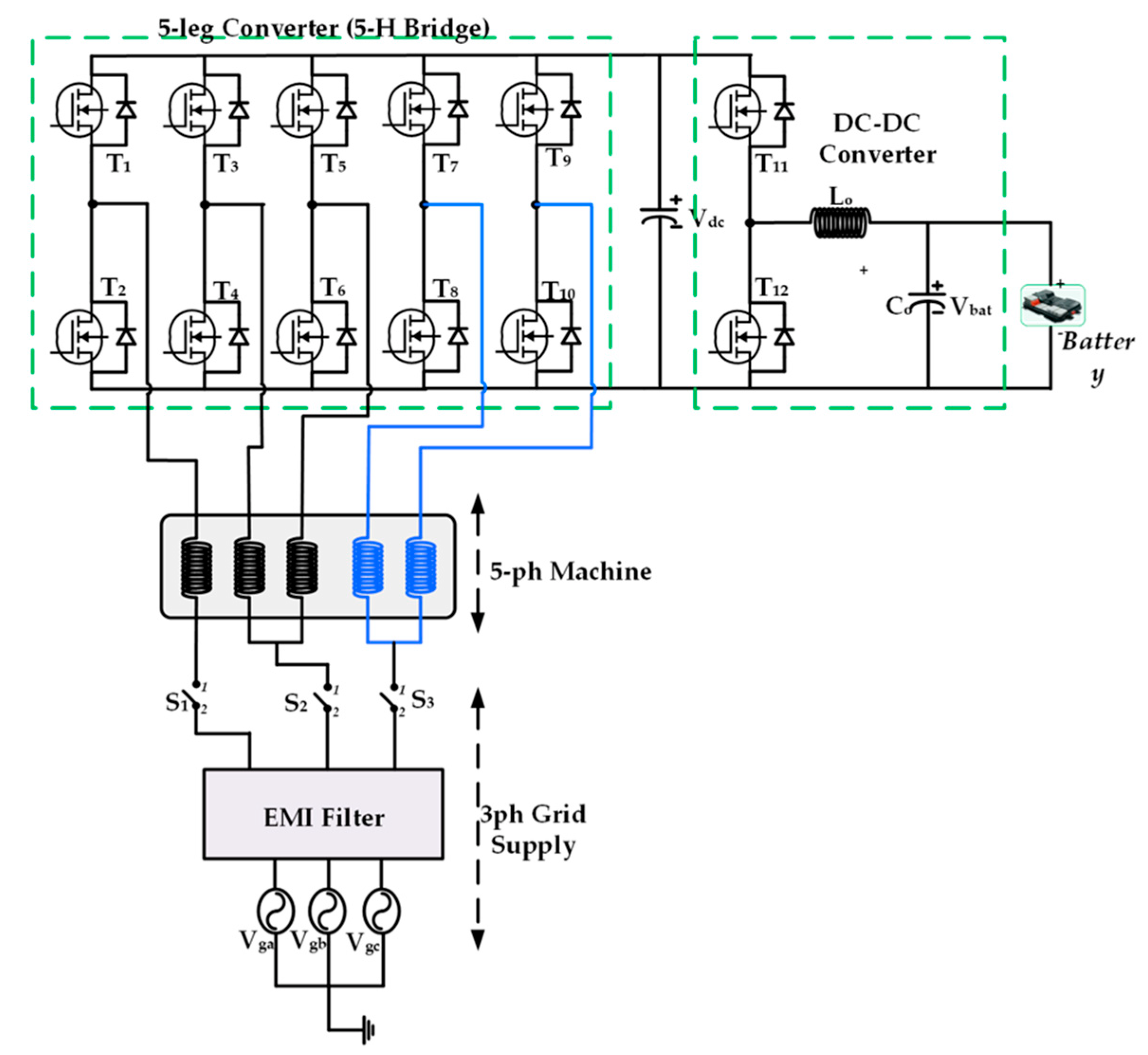
Figure 17. Integrated On−Board Charger based on Five Phase Winding Machine proposed by Sabotic et al. [42] in 2016 (iOBC14).
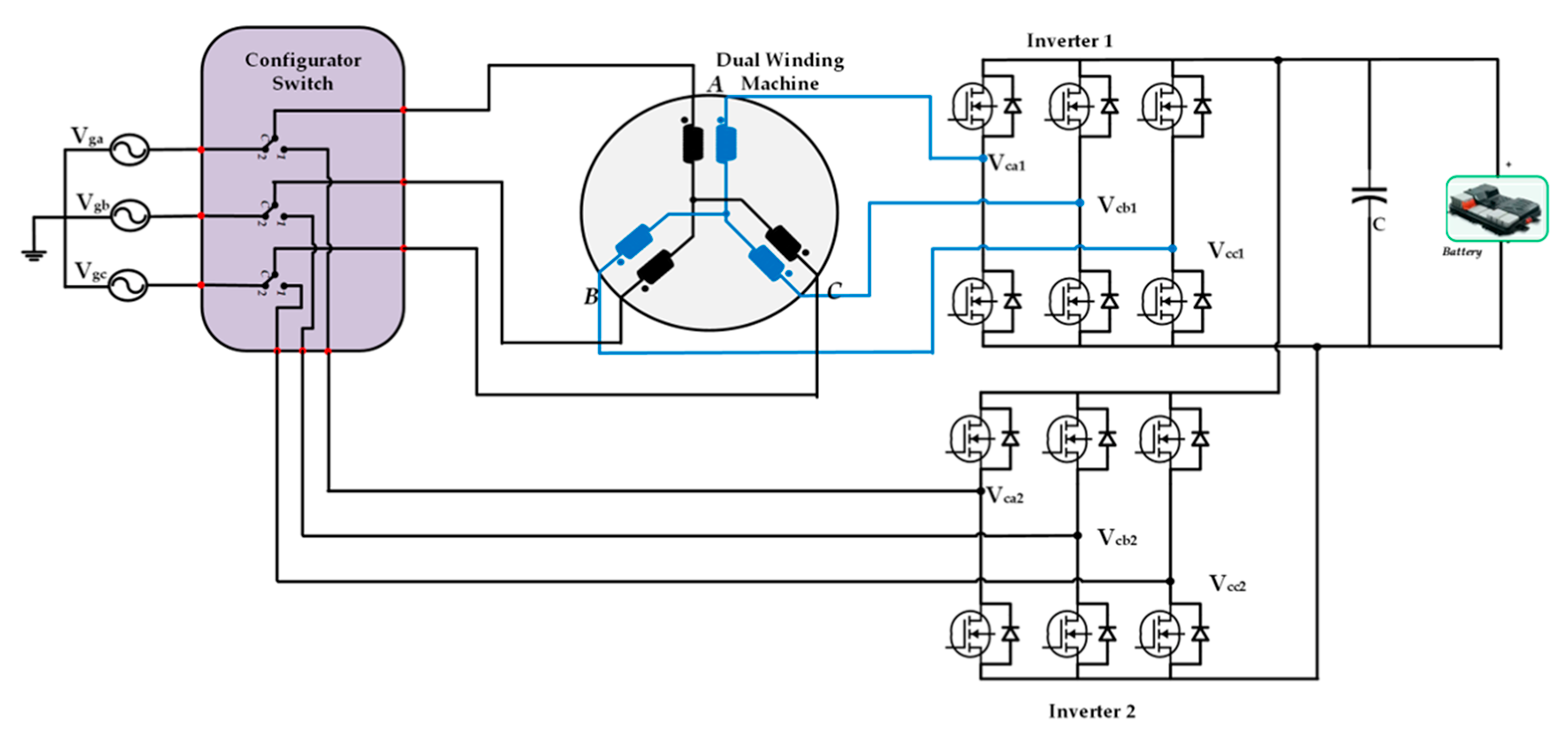
Figure 18. Isolated Integrated On−Board Charger based on Six Phase Machine Reconfiguration proposed by Pascetto et al. [48] in 2020 (iOBC15).
To sum up, researchers have seen the different aspects of the previously mentioned topologies, showing technical features such as V2G, torque ripple issues, and torque generation during charging. Thus, all topologies are compared according to the average torque production during the charging process, hardware reconfiguration between the propulsion and the charging modes, V2G feature, torque ripple issues, and the charging power as a ration of the traction power.
References
- Element Energy Limited. Electric Cars: Calculating the Total Cost of Ownership for Consumers; Element Energy Limited: Cambridge, UK, 2021; p. 44.
- Habib, S.; Khan, M.M.; Abbas, F.; Sang, L.; Shahid, M.U.; Tang, H. A Comprehensive Study of Implemented International Standards, Technical Challenges, Impacts and Prospects for Electric Vehicles. IEEE Access 2018, 6, 13866–13890.
- Ahmad, A.; Alam, M.S.; Chabaan, R. A Comprehensive Review of Wireless Charging Technologies for Electric Vehicles. IEEE Trans. Transp. Electrif. 2017, 4, 38–63.
- Trends and Developments in Electric Vehicle Markets—Global EV Outlook 2021—Analysis—IEA. Available online: https://www.iea.org/reports/global-ev-outlook-2021/trends-and-developments-in-electric-vehicle-markets (accessed on 25 September 2021).
- Chakraborty, S.; Vu, H.N.; Hasan, M.M.; Tran, D.D.; El Baghdadi, M.; Hegazy, O. DC-DC converter topologies for electric vehicles, plug-in hybrid electric vehicles and fast charging stations: State of the art and future trends. Energies 2019, 12, 1569.
- Schmenger, J.; Endres, S.; Zeltner, S.; März, M. A 22 kW on-board charger for automotive applications based on a modular design. In Proceedings of the 2014 IEEE Conference on Energy Conversion (CENCON), Johor Bahru, Malaysia, 13–14 October 2014; pp. 1–6.
- Yang, G.; Lindseth, R.; Sorsdahl, T. Design of High Efficiency High Power Density 10.5 kW Three Phase On-board-charger for Electric/hybrid Vehicles. In Proceedings of the PCIM Europe 2016; International Exhibition and Conference for Power Electronics, Intelligent Motion, Renewable Energy and Energy Management, Nuremberg, Germany, 10–12 May 2016; pp. 10–12.
- Semsar, S.; Soong, T.; Lehn, P.W. On-Board Single-Phase Integrated Electric Vehicle Charger with V2G Functionality. IEEE Trans. Power Electron. 2020, 35, 12072–12084.
- Tran, V.T.; Rabiul Islam, M.; Muttaqi, K.M.; Sutanto, D. A Novel Universal Magnetic Power Plug to Facilitate V2V/V2G/G2V/V2H Connectivity for Future Grid Infrastructure. In Proceedings of the Conference Record of the IEEE Industry Applications Society Annual Meeting (IAS), Detroit, MI, USA, 10–16 October 2020.
- Yilmaz, M.; Krein, P.T. Review of Battery Charger Topologies, Charging Power Levels, and Infrastructure for Plug-In Electric and Hybrid Vehicles. IEEE Trans. Power Electron. 2013, 28, 2151–2169.
- Hegazy, O.; van Mierlo, J.; Lataire, P. Control and analysis of an integrated bidirectional DC/AC AND DC/DC converters for plug-in hybrid electric vehicle applications. J. Power Electron. 2011, 11, 408–417.
- Song, H.S.; Yoo, I.P.; Jang, K.Y.; Shin, S.; Joo, J.H. System for Recharging Plug-in Electric Vehicle and Control Method for the Same. U.S. Patent US 8441229 B2, 2 May 2013.
- Sarrazin, B. Optimisation d’une Chaîne de Traction pour Véhicule Électrique. Energie Électrique; ⟨NNT: 2012GRENT117⟩. ⟨tel-00808946v2⟩; Université de Grenoble: Saint-Martin-d’Hères, France, 2012; (In Français).
- Gupta, J.; Maurya, R.; Arya, S.R. Improved Power Quality On-Board Integrated Charger with Reduced Switching Stress. IEEE Trans. Power Electron. 2020, 35, 10810–10820.
- Woo, D.G.; Joo, D.M.; Lee, B.K. On the Feasibility of Integrated Battery Charger Utilizing Traction Motor and Inverter in Plug-In Hybrid Electric Vehicles. IEEE Trans. Power Electron. 2015, 30, 7270–7281.
- Tang, L.; Su, G.J. Control scheme optimization for a low-cost, digitally-controlled charger for plug-in hybrid electric vehicles. In Proceedings of the 2009 IEEE Energy Conversion Congress and Exposition, San Jose, CA, USA, 20–24 September 2009; pp. 3604–3610.
- Subotic, I.; Jones, M.; Levi, E. A fast on-board integrated battery charger for four-motor EVs. In Proceedings of the 2014 International Conference on Electrical Machines (ICEM), Berlin, Germany, 2–5 September 2014; pp. 2066–2072.
- Sul, S.K.; Lee, S.J. An Integral Battery Charger for Four-Wheel Drive Electric Vehicle. IEEE Trans. Ind. Appl. 1995, 31, 1096–1099.
- Khan, M.A.; Husain, I.; Sozer, Y. Integrated electric motor drive and power electronics for bidirectional power flow between electric vehicle and DC or AC grid. In Proceedings of the IEEE Energy Conversion Congress and Exposition, ECCE, Raleigh, NC, USA, 15–20 September 2012; pp. 3403–3410.
- Tuan, V.T.; Phattanasak, M.; Kreuawan, S. Integrated charger-inverter for high-performance electric motorcycles. World Electr. Veh. J. 2021, 12, 19.
- Khayam Huseini, S.R.; Farjah, E.; Tashakor, N.; Ghanbari, T. Development of an integrated Switched-Reluctance Motor drive with battery charging capability for electric vehicle propulsion system. In Proceedings of the 6th Power Electronics, Drive Systems & Technologies Conference (PEDSTC2015), Tehran, Iran, 3–4 February 2015; pp. 579–584.
- Hu, K.W.; Yi, P.H.; Liaw, C.M. An EV SRM Drive Powered by Battery/Supercapacitor with G2V and V2H/V2G Capabilities. IEEE Trans. Ind. Electron. 2015, 62, 4714–4727.
- Shi, C.; Tang, Y.; Khaligh, A. A Three-Phase Integrated Onboard Charger for Plug-In Electric Vehicles. IEEE Trans. Power Electron. 2018, 33, 4716–4725.
- De Sousa, L.; Silvestre, B.; Bouchez, B. A combined multiphase electric drive and fast battery charger for electric vehicles: Topology and electric propulsion efficency analysis. In Proceedings of the 2010 IEEE Vehicle Power and Propulsion Conference, Lille, France, 1–3 September 2010.
- Sandulescu, A.P.; Meinguet, F.; Kestelyn, X.; Semail, E.; Bruyere, A. Flux-weakening operation of open-end winding drive integrating a cost-effective high-power charger. IET Electr. Syst. Transp. 2013, 3, 10–21.
- Lacroix, S.; Laboure, E.; Hilairet, M. An integrated fast battery charger for electric vehicle. In Proceedings of the 2010 IEEE Vehicle Power and Propulsion Conference, Lille, France, 1–3 September 2010; pp. 1–6.
- Haghbin, S.; Carlson, O. Integrated motor drive and non-isolated battery charger based on the split-phase PM motors for plug-in vehicles. J. Eng. 2014, 2014, 275–283.
- Bruyère, A.; De Sousa, L.; Bouchez, B.; Sandulescu, P.; Kestelyn, X.; Semail, E. A multiphase traction/fast-battery-charger drive for electric or plug-in hybrid vehicles: Solutions for control in traction mode. In Proceedings of the 2010 IEEE Vehicle Power and Propulsion Conference, Lille, France, 1–3 September 2010; pp. 1–7.
- Bruell, M.; Brockerhoff, P.; Pfeilschifter, F.; Feustel, H.P.; Hackmann, W. Bidirectional charge- and traction-system. World Electr. Veh. J. 2016, 8, 237–248.
- Sharma, S.; Aware, M.V.; Bhowate, A. Integrated Battery Charger for EV by Using Three-Phase Induction Motor Stator Windings as Filter. IEEE Trans. Transp. Electrif. 2020, 6, 83–94.
- Chon, C.; Duck, K.; Jung, H.; Tae, H.; Noh, S.H. Multi-Input Charging System and Method Using Motor Driving System 2020. Available online: https://www.freepatentsonline.com/y2020/0361323.html (accessed on 1 October 2021).
- Scelba, G.; Scarcella, G.; Foti, S.; De Caro, S.; Testa, A. Self-sensing control of open-end winding PMSMS fed by an asymmetrical hybrid multilevel inverter. In Proceedings of the 2017 IEEE International Symposium on Sensorless Control for Electrical Drives (SLED), Catania, Italy, 18–19 September 2017; pp. 165–172.
- Hoevenaars, E.; Illg, T.; Hiller, M. Novel integrated charger concept using an induction machine as transformer at standstill. In Proceedings of the 2020 IEEE Vehicle Power and Propulsion Conference (VPPC), Gijon, Spain, 18 November–16 December 2020.
- Asymmetrical, T.I.; Pmsm, S. Common-Mode Voltage Elimination for Dual. IEEE Trans. Power Electron. 2020, 35, 3828–3840.
- Su, G.J.; Tang, L. An integrated onboard charger and accessory power converter using WBG devices. In Proceedings of the 2015 IEEE Energy Conversion Congress and Exposition (ECCE), Montreal, QC, Canada, 20–24 September 2015; pp. 6306–6313.
- Han, X.; Jiang, D.; Zou, T.; Qu, R.; Yang, K. Two-Segment Three-Phase PMSM Drive with Carrier Phase-Shift PWM for Torque Ripple and Vibration Reduction. IEEE Trans. Power Electron. 2018, 34, 588–599.
- Raherimihaja, H.J.; Zhang, F.; Na, T.; Zhang, Q. An integrated charger using segmented windings of interior permanent magnet motor based on 3 phase with 9 windings. In Proceedings of the 2018 13th IEEE Conference on Industrial Electronics and Applications (ICIEA), Wuhan, China, 31 May–2 June 2018; pp. 565–570.
- Szenasy, I.; Varga, Z. Features of segment winded PMSM for a low voltage supply system. In Proceedings of the 2017 3rd International Conference on Control, Automation and Robotics (ICCAR), Nagoya, Japan, 24–26 April 2017; pp. 523–528.
- Abdel-Khalik, A.S.; Ahmed, S.; Massoud, A.M. A Nine-Phase Six-Terminal Concentrated Single-Layer Winding Layout for High-Power Medium-Voltage Induction Machines. IEEE Trans. Ind. Electron. 2017, 64, 1796–1806.
- Bodo, N.; Levi, E.; Subotic, I.; Espina, J.; Empringham, L.; Johnson, C.M. Efficiency Evaluation of Fully Integrated On-Board EV Battery Chargers With Nine-Phase Machines. IEEE Trans. Energy Convers. 2017, 32, 257–266.
- Diab, M.S.; Elserougi, A.A.; Abdel-Khalik, A.S.; Massoud, A.M.; Ahmed, S. A Nine-Switch-Converter-Based Integrated Motor Drive and Battery Charger System for EVs Using Symmetrical Six-Phase Machines. IEEE Trans. Ind. Electron. 2016, 63, 5326–5335.
- Subotic, I.; Bodo, N.; Levi, E. An EV Drive-Train With Integrated Fast Charging Capability. IEEE Trans. Power Electron. 2016, 31, 1461–1471.
- Subotic, I.; Levi, E.; Jones, M.; Graovac, D. Multiphase integrated on-board battery chargers for electrical vehicles. In Proceedings of the 2013 15th European Conference on Power Electronics and Applications (EPE), Lille, France, 2–6 September 2013; pp. 1–10.
- Tong, M.; Cheng, M.; Wang, S.; Hua, W. An On-Board Two-Stage Integrated Fast Battery Charger for EVs Based on a Five-Phase Hybrid-Excitation Flux-Switching Machine. IEEE Trans. Ind. Electron. 2021, 68, 1780–1790.
- Subotic, I.; Bodo, N.; Levi, E.; Jones, M.; Levi, V. Isolated chargers for EVs incorporating six-phase machines. IEEE Trans. Ind. Electron. 2016, 63, 653–664.
- Haghbin, S.; Lundmark, S.; Alaküla, M.; Carlson, O. An isolated high-power integrated charger in electrified-vehicle applications. IEEE Trans. Veh. Technol. 2011, 60, 4115–4126.
- Abdel-Khalik, A.S.; Massoud, A.; Ahmed, S. Interior permanent magnet motor-based isolated on-board integrated battery charger for electric vehicles. IET Electr. Power Appl. 2018, 12, 124–134.
- Pescetto, P.; Pellegrino, G. Integrated Isolated OBC for EVs with 6-phase Traction Motor Drives. In Proceedings of the 2020 IEEE Energy Conversion Congress and Exposition (ECCE), Detroit, MI, USA, 11–15 October 2020; pp. 4112–4117.
More
Information
Subjects:
Engineering, Electrical & Electronic
Contributors
MDPI registered users' name will be linked to their SciProfiles pages. To register with us, please refer to https://encyclopedia.pub/register
:
View Times:
7.7K
Revisions:
3 times
(View History)
Update Date:
17 Aug 2022
Table of Contents


Notice
You are not a member of the advisory board for this topic. If you want to update advisory board member profile, please contact office@encyclopedia.pub.
OK
Confirm
Only members of the Encyclopedia advisory board for this topic are allowed to note entries. Would you like to become an advisory board member of the Encyclopedia?
Yes
No
${ textCharacter }/${ maxCharacter }
Submit
Cancel
Back
Comments
${ item }
|
${ item.createdUser.fullName }
${ item.createdAt }
${ item.vote }
${ item.reply }
Delete
${ reply.createdUser.fullName }
${ reply.createdAt }
${ reply.vote }
Delete
There is no reply to this comment~
${ item.replyTextCharacter }/${ item.replyMaxCharacter }
Submit
Cancel
More
No more~
There is no comment~
${ textCharacter }/${ maxCharacter }
Submit
Cancel
${ selectedItem.replyTextCharacter }/${ selectedItem.replyMaxCharacter }
Submit
Cancel
Confirm
Are you sure to Delete?
Yes
No