Your browser does not fully support modern features. Please upgrade for a smoother experience.
Submitted Successfully!
 +1 credit
Thank you for your contribution! You can also upload a video entry or images related to this topic.
For video creation, please contact our Academic Video Service.
| Version | Summary | Created by | Modification | Content Size | Created at | Operation |
|---|---|---|---|---|---|---|
| 1 | Baseem Khan | -- | 4849 | 2022-08-08 04:10:41 | | | |
| 2 | Catherine Yang | Meta information modification | 4849 | 2022-08-08 04:22:28 | | |
Video Upload Options
We provide professional Academic Video Service to translate complex research into visually appealing presentations. Would you like to try it?
Cite
If you have any further questions, please contact Encyclopedia Editorial Office.
Khan, B.; Guerrero, J.M.; Chaudhary, S.; Vasquez, J.C.; Frederiksen, K.H.B.; Wu, Y. Grid Code Requirements in Ethiopia. Encyclopedia. Available online: https://encyclopedia.pub/entry/25932 (accessed on 13 July 2026).
Khan B, Guerrero JM, Chaudhary S, Vasquez JC, Frederiksen KHB, Wu Y. Grid Code Requirements in Ethiopia. Encyclopedia. Available at: https://encyclopedia.pub/entry/25932. Accessed July 13, 2026.
Khan, Baseem, Josep M. Guerrero, Sanjay Chaudhary, Juan C. Vasquez, Kenn H. B. Frederiksen, Ying Wu. "Grid Code Requirements in Ethiopia" Encyclopedia, https://encyclopedia.pub/entry/25932 (accessed July 13, 2026).
Khan, B., Guerrero, J.M., Chaudhary, S., Vasquez, J.C., Frederiksen, K.H.B., & Wu, Y. (2022, August 08). Grid Code Requirements in Ethiopia. In Encyclopedia. https://encyclopedia.pub/entry/25932
Khan, Baseem, et al. "Grid Code Requirements in Ethiopia." Encyclopedia. Web. 08 August, 2022.
Copy Citation
Rapid integration of renewable energy into the electric grid has ramifications for grid management and planning. Therefore, system operators have formulated grid code requirements to ensure that the grid continues to operate in a secure, safe, and cost-effective manner. The current state of grid code in Ethiopia, as well as the need for it, is discussed here. It lays out the technological grid integration requirements, with a focus on small and microgrids, which are especially important for the integration of renewable.
grid code
minigrid
microgrid
renewable energy integration
1. Introduction
The availability of energy is a major factor in global economic shifts. Energy security is a vital problem for industrialization and economic progress, as it helps to alleviate poverty, improve food production, improve clean water availability, update healthcare centers, raise standards of education, and generate work opportunities for young people, especially women. One out of every five individuals in the world does not have access to power. Several individuals still use charcoal, wood, agricultural waste, as well as other solid fuels for cooking and other daily activities; consequently, they suffer from several health problems that shorten their lives. Inadequate power availability has an impact on a family’s income, industrial productivity, education, and health. Due to emissions from greenhouse gases, contemporary energy-producing units based on fossil fuels have an adverse impact on the climate and the environment [1]. At a national and international level, these atmospheric shifts cause water and food problems. Security of energy supply from renewable energy sources is crucial for sustainable development. Although there has been a significant improvement in alternative sources of energy, there are still several constraints that must be resolved in order to achieve large-scale sustainable growth. Many breakthroughs in technology, financial strategy, marketing strategies, regulatory, and governance frameworks are essential for sustainable power generation. In terms of global growth, African countries have a relatively low rate of sustainable development due to insufficient energy generation and availability [2]. There are three major energy concerns in sub-Saharan Africa: inadequacy of energy generation, insufficient energy access, and global warming. To limit the effects of global warming, these difficulties must be handled so that 100% availability of power may be achieved via renewable energy-producing infrastructure.
1.1. Ethiopian Energy Sector
Ethiopia is a nation in the Horn of Africa region. The Ethiopian government is adamant about increasing power generation and accessibility for all of its 130 million citizens. Various international organizations such as World Bank, African Development Bank, etc., contribute to various energy and electricity initiatives [3]. In order to determine the impact of rural grid extension on various degrees of deprivation, a thorough and comprehensive investigation is essential. There are several proofs known on the consequences of poverty on Asian nations, but comprehensive empirical evaluations for African countries are scarce [3].
1.1.1. Background
The majority of people in Africa reside in rural areas and carry out subsistence farming and other activities linked to agriculture. Oil seeds, legumes, fruits, flowers, natural gum, spices, textiles, and mineral products are among Ethiopia’s exports in addition to coffee, leather, live animals, and meat. Ethiopia’s economy is among the most rapidly developing in the African region, and the nation’s economy is being stabilized and rehabilitated [3]. Ethiopia, like other sub-Saharan African nations, needs enough power generation and fair access to power. The urban population has extensive access to energy, while the rural areas have limited access to electricity. Ethiopia has one of the least power usage rates in the world, with some of the urban areas such as Addis Ababa, Hawassa, Jimma, Bahirdar consuming the majority of it. The administration is addressing the longstanding issue of a lack of energy supply in rural regions and expanding access to modern energy. As a result, a variety of initiatives are being undertaken in collaboration with foreign governments. The rural electrification connectivity initiative has been continuously funded by the Ethiopian government, with other financial institutions such as World Bank, etc., since 1998, with the goal of achieving nationwide electrification of 90%. Apart from conventional energy production, non-conventional power generation units such as photo-voltaic, wind, and geothermal have been built and procured [4].
1.1.2. Overview
Ethiopia’s government wants to improve energy availability from 26% in 2014 to 60% by 2040. Another goal is to improve the effectiveness of current power production facilities. To carry out such specific goals, the Ethiopian government is constantly organizing fresh monetary capacity from China, in addition to traditional World Bank funds. The Universal Power Access Program (UEAP) was created to ensure that most rural communities have reliable electricity. The entire cost of the UEAP is estimated to be around USD 920 million. The Ethiopian Electric Power (EEP) has devised an integrated plan to achieve these objectives [4]. Ethiopia has a huge power grid that is integrated (ICS). There are 13 hydro, 6 diesel standby, 1 geothermal, and 4 wind farms in this ICS. Ethiopia now has 23 power plants that use hydropower, wind energy, geothermal energy, and diesel to generate electricity. In the fiscal year 2020–21, energy output is expected to be about 4523.77 MW [1].
1.1.3. Ethiopia’s Renewable Energy Sector
Ethiopia now has a total installed capacity for electricity generation of about 4238 MW. Nearly 90% of the electricity is produced by hydropower plants (3807 MW). In concert, 324 MW (7.65%), 7.3 MW (0.17%), and 99.17 MW (2.34%) are produced by wind, geothermal, and diesel energy facilities, respectively. Alternative energy sources, such as hydropower, wind, solar, and geothermal energy as well as diesel, have a lot of promise in Ethiopia. Despite the enormous potential for producing renewable energy, only a small amount of green energy is generated as a result of a lack of funding and other important problems. Ethiopia continues to be on the cusp of a renewable power revolution.
1.1.4. Renewable Energy-Based Minigrid Clusters in Ethiopia (REMCE)
The REMCE project, which was supported by the Danida Project, includes this paper. The primary goal of this endeavor is to complete this paper. The REMCE project intends to increase access to electricity in Ethiopia’s rural areas while addressing the difficulties associated with the large-scale implementation of sustainable power minigrids. In order to carry this out, REMCE will gather and analyze the pertinent data and information in order to assess and choose the best minigrid designs and locations in Ethiopia. To meet the need for electricity in Ethiopia’s distant locations, REMCE will suggest the appropriate activities and procedures. The project will focus on solar and wind resources in combination with diesel generators, or preferably battery energy storage systems and micro-hydropower systems to implement multiple minigrids. These minigrids will be interconnected forming clusters with high levels of efficiency, scalability, and expandability. The main objectives of this project are the development of the grid code for the incorporation of the minigrid and microgrid into the utility grid, develop minigrid and microgrid clusters for the remote areas of the remote Ethiopian areas, optimal controlling of the proposed mini and microgrids and integrate them to the utility grid.
2. Existing Ethiopian Grid Codes for the Integration of Renewable Energy Sources
The Grid Code (GC) outlines the regulations required for the overall administration and evaluates the Ethiopia National Distribution System Grid Code’s (ENDS-GC) various aspects.
Grid codes’ technical standards establish the electrical characteristics that generating assets must meet in order to acquire the necessary permission for grid integration. As a result, establishing grid code compliance and obtaining a grid connection agreement are critical benchmarks in the evolution of RPP projects.
An authority in charge of system integrity and network functioning specifies and implements the grid code. Its execution often involves system operators including distribution grid operators, consumers, and the governmental entity. The contents of a grid code vary based on the utility company’s needs.
The needed performance of linked RPPs under network disruptions will specify the technical validity of a GC. Voltage control, power factor restrictions and reactive power requirement, reaction to network failures, responsiveness to frequency variations on the grid, and the necessity of ride-through capabilities for small interruptions of the connection are all examples.
2.1. Technical Specifications for Renewable Energy Sources Integration at Distribution Level
A renewable power plant (RPP) should have the capabilities to fulfill future grid requirements, but until the RPP reaches a certain size of MW capacity or is connected to the main grid, some of the requirements of the grid code can be less strict. Such requirements can be voltage band, frequency band, disconnection times during under voltage, etc. The technical requirements, limits, and ranges of constraints are described below.
2.1.1. Normal Operating Conditions
RPPs of β category can be linked to the Ethiopian national distribution supply system at the point of consumption (POC). The difference in installed capability among phases in multi-phase supply linkages must not exceed 4.6 kVA/phase.
- (a)
-
RPPs of the category β and γ must be capable of running consistently within the POC operating voltage (0.9–1.1 p.u. at 66 kV, and 0.9–1.08 p.u. for voltages lower than 66 kV).
- (b)
-
RPPs of the category β and γ are only permitted to interface to the ENDS for a maximum of 3 s once the preceding criterion is met:
-
The potential at the POC is between the maximal and lowest allowed ranges set out in item (a) above;
-
ENDS’s frequency is between 49.0 and 50.2 Hz.
RPPs of α category are only permitted to link to the ENDS power network for a maximum of 60 s just after succeeding criteria are met:
-
The allowable variation in potential at the point of consumption is between −15% and +10% of the normal voltage
-
The ENDS frequency is between 49.0 and 50.2 Hz, unless so approved by the regional dispatch center.
- (c)
-
The ENDS’ nominal frequency is 50 Hz, and it is generally regulated by the regulations of the Ethiopian national distribution grid code specifications. The RPP must be configured to operate within the minimal operating ranges shown in Figure 1 and Figure 2 at the time of network frequency issues.
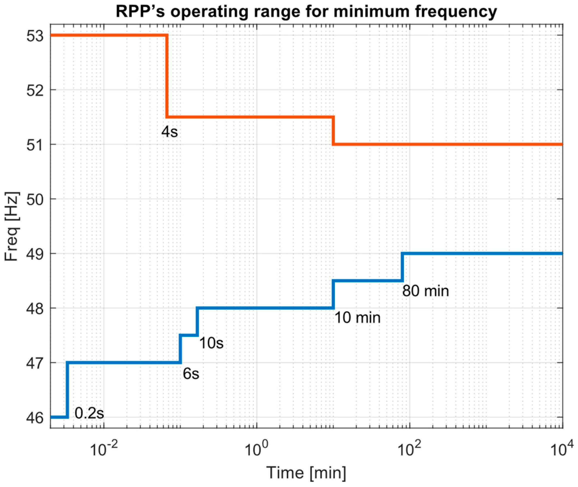 Figure 1. Minimum frequency operating range for RPP.
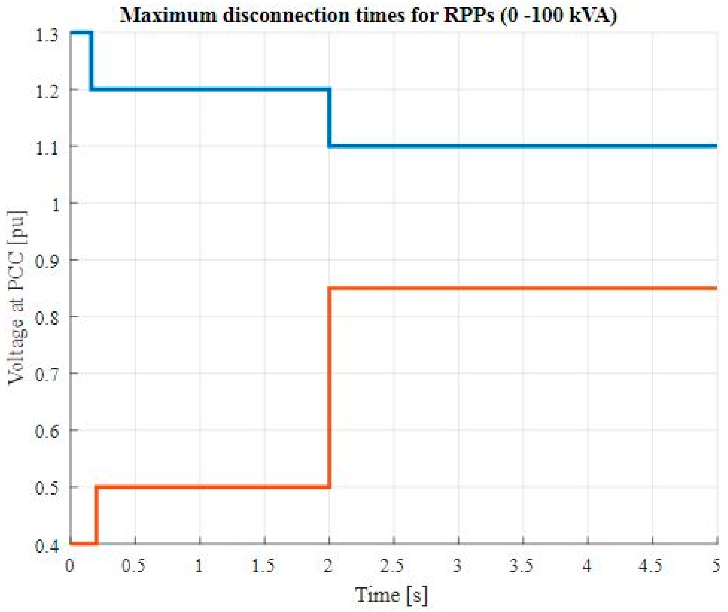 Figure 2. Maximum disconnection times for RPPs of α category.
 - (d)
-
The RPP may be eliminated if the ENDS frequency exceeds 51.5 Hz for more than 4 s or if it dips below 47.0 Hz for more than 200 milliseconds. The RPP shall continue to be connected to the ENDS even if the system frequency varies up to and including 1.5 Hz per second as long as it continues within the minimal level operational range shown in Figure 1 and Figure 2.
2.1.2. Operating Conditions under Disturbance
At the point of consumption, the RPP must be able to withstand fast phase jumps of up to 20 degrees while still remaining connected and functional. No later than 5 s after the operating conditions in the point of consumption have returned to normal, the RPP must start regular production.
-
Voltage Response
RPPs of the category of α must be able to resist and satisfy voltage ride-through capabilities (VRTCs) as shown in Figure 3 and Figure 4 at the point of use.
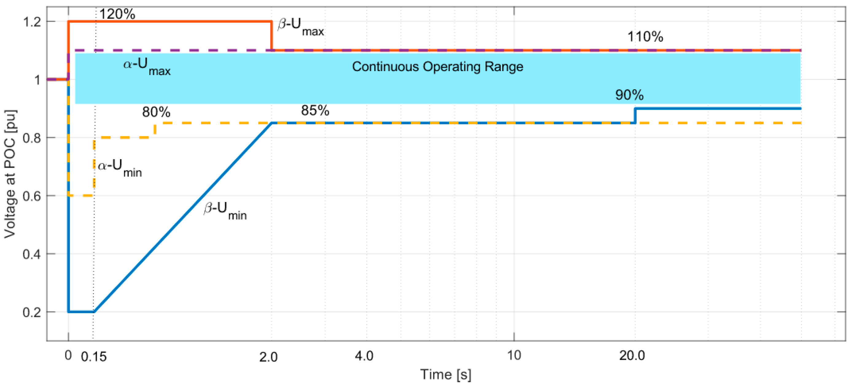
Figure 3. VRTC for the RPPs of α, β, and γ categories RPPs.
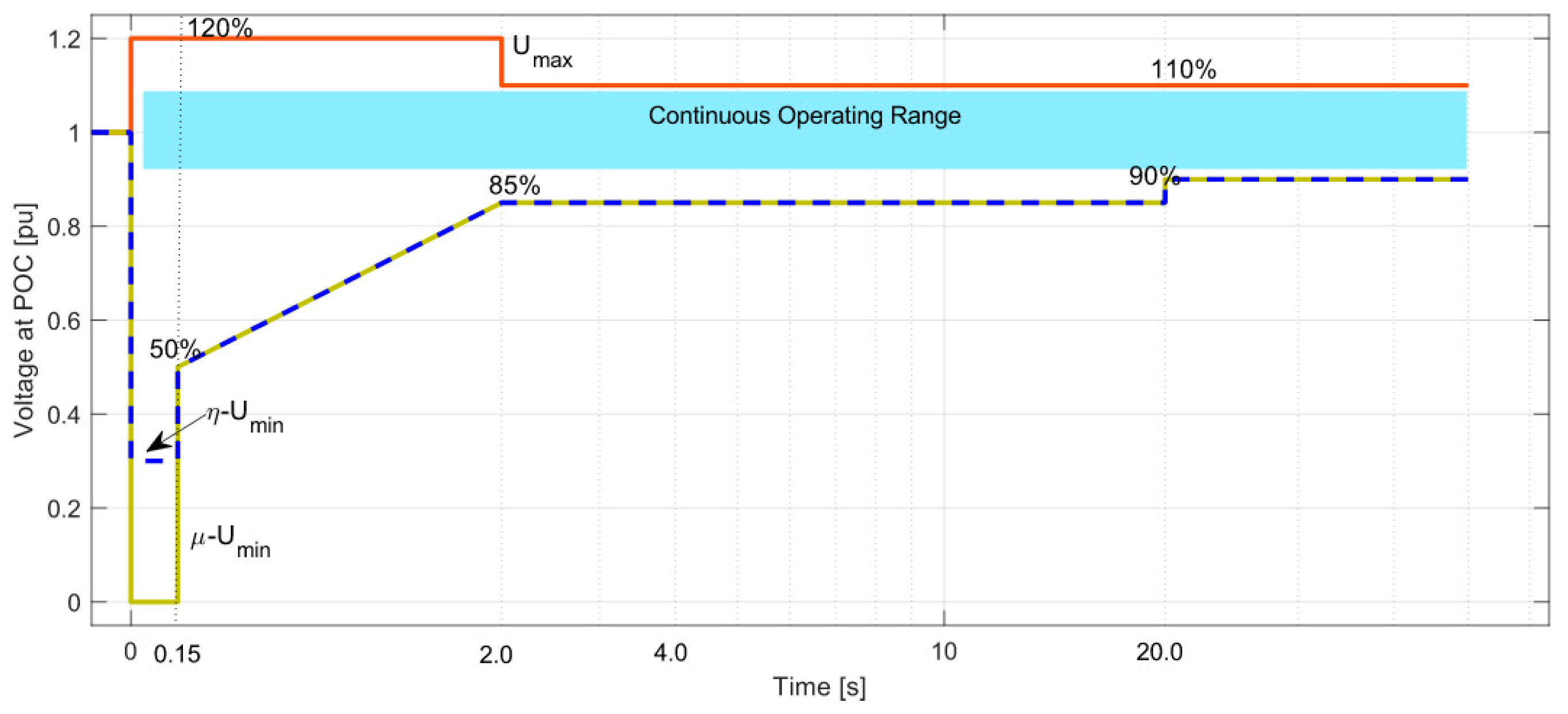
Figure 4. VRTC for the RPPs of μ, δ, and η categories RPPs.
RPPs having different capacities such α, β, γ, δ, μ, and η must be able to resist and meet the voltage conditions indicated in this section, as well as those depicted in Figure 3 and Figure 4. Without disconnecting, the RPP must endure voltage decreases and peaks, as shown in Figure 3 and Figure 4, and provide or absorb reactive current. As shown in Figure 3 and Figure 4, the RPP must be able to withstand voltage drops to zero, measured at the point of consumption, for a minimum of 0.150 s before detaching, with the exception of synchronous generator-based RPPs of μ (1–20 MVA) during symmetrical three-phase failures. The RPP category of δ must be capable of withstanding voltage peaks up to 120 percent of the normal voltage measured at the point of consumption for a minimum of 2 s without disconnecting, as shown in Figure 4 and Figure 5.
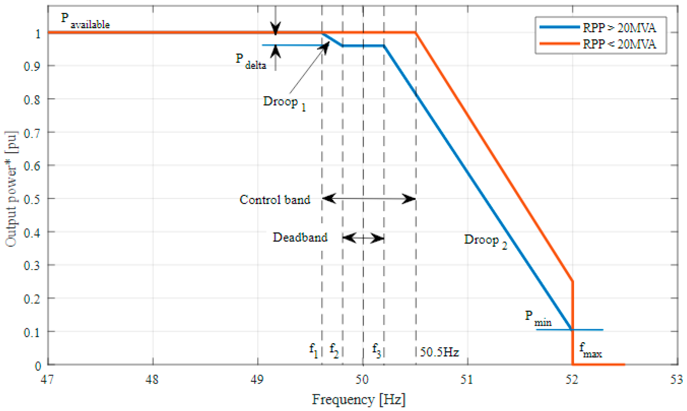
Figure 5. RPPs of higher capacity size (20 MVA and above) Frequency responses. * Power output from RPPs (20 MVA and above).
The voltage at POC is between the minimum and maximum voltage curves for the specified durations, and then the RPPs must remain connected. The RPPs must inject reactive current as a function of voltage deviation (from 80%) when the voltage is lower than 80%. Maximum reactive current should be injected when the voltage at the POC is 50% or less. Similarly, if the voltage is more than 110%, the RPPs must absorb reactive power.
- B.
-
Frequency Response
The power frequency response curve agreed upon by the system operator and regional control center must be met by the frequency response system of RPPs.
- 1.
-
Power–Frequency Response Curve for RPP
In order to maintain frequency stability during high frequency operating conditions, RPPs must be able to provide necessary active power reduction needs, as seen in Figure 5. Metering accuracy for the grid frequency must be at least 10 mHz. As shown in Figure 5, the RPP must reduce active power as a function of frequency change when the frequency on the ENDS exceeds 50.5 Hz. For the sake of protecting the ENDS, the RPP is unplugged when the frequency exceeds 51.5 Hz for more than 4 s.
- 2.
-
Power–Frequency Response Curve for RPP of δ category
Figure 5 shows how RPPs must be able to provide power–frequency response. The RPP is not required to execute any frequency response functions other than the mandated high-frequency response (above 50.5 Hz). Without a special agreement with the distribution network system planner (DNSP), Regional Control Center, and/or the ENTSO, no PDelta, dead-band, or control-band functions shall be implemented. The term “PDelta” refers to the active power that has been reduced in order to provide reserves for frequency stability. The frequency response control function needs to be able to regulate each and every frequency point in Figure 5. With a minimum accuracy of 10 mHz, the frequencies fmin, fmax, and f1 through f6 must be able to be modified to any value between 47 and 52 Hz. Frequency points f1 through f4 operate as a dead band and a control band for RPPs contracted for the main frequency response. The requisite critical power/frequency response is provided by the frequency points f4 through f6. The frequency control droop parameters, as shown in Figure 5, must be included in the RPP. Each droop parameter must be able to be adjusted between 0% and 10%. The system operator will be consulted to decide the precise droop setting. The droop settings required to govern between the distinct frequency points must be determined by the system operator and sent to the RPP. If the active power from the RPP is managed underneath the unit’s design limit Pmin, individual RPP units may shut down. The RPP (excluding photovoltaic solar) must be able to provide a PDelta of at least 3% of the total Pavailable. The frequency response control feature must be able to be activated and deactivated in the range of fmin to fmax. If the frequency control set point (i.e., PDelta) is to be altered, the change must be started within two seconds and finished within ten seconds of receiving the change order. Regardless of which creates the highest tolerance, the accuracy of the executed control and the set point cannot deviate by more than 2 percent of the set point value or 0.5 percent of the rated power. Unless the system operator and the RPP generator agree differently, the default parameters for fmin, fmax, f4, f5, and f6 are 47 Hz, 52 Hz, 50.5 Hz, 51.5 Hz, and 50.2 Hz, respectively. The system operator must approve the settings for f1, f2, and f3, as per the agreement.
The Regional Control Center and/or the system operator must provide the RPP with at least two weeks’ notice if any of the frequency response parameters (i.e., f1 through f6) need to be altered. The RPP shall confirm with the Regional Control Center and/or the system operator that the appropriate changes have been made within two weeks of receiving the request from the Regional Control Center and/or the system operator.
- C.
-
Reactive Power Capability
- 1.
-
RPPs of α category (below 1 MVA)
The α Category RPPs must operate at unity power factor measured at POC unless the Regional Control Center and/or the system operator stipulate otherwise. As assessed at the POC available from 20 percent to 100 percent of rated power, RPPs of β category must be able to operate at power factors ranging from 0.95 lagging to 0.95 leading (Pn). A power factor characteristic curve that RPPs can follow will be developed by the Regional Control Center and/or the system operator. The default power factor value is unity unless the regional control center and/or system operator specify otherwise.
- 2.
-
RPPs of γ category
The ability to operate in voltage (V), power factor, or reactive power control modes is a requirement for RPPs in this category. The distribution network system planner (DNSP) must be consulted in order to identify the precise operating point and operating mode (voltage, power factor, or reactive power regulation). Within the reactive power capability ranges shown in in Figure 6 and Figure 7 the RPPs in γ and δ categories must be able to support varying reactive power (MVAr) at the POC when operating between 5 and 100 percent of rated power Pn (MW). Figure 7 shows the reactive power capability of the RPPs of γ and δ categories at nominal voltage.
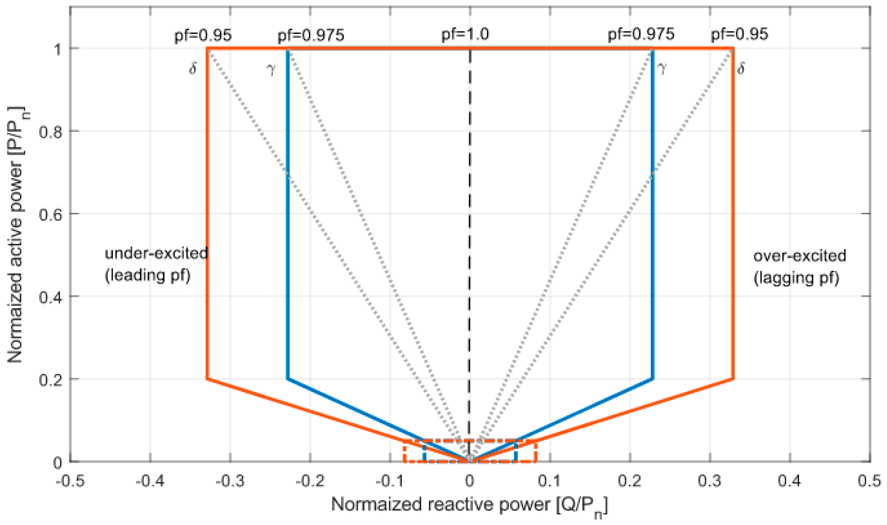
Figure 6. Reactive power requirements for RPPs of γ and δ categories at POC.
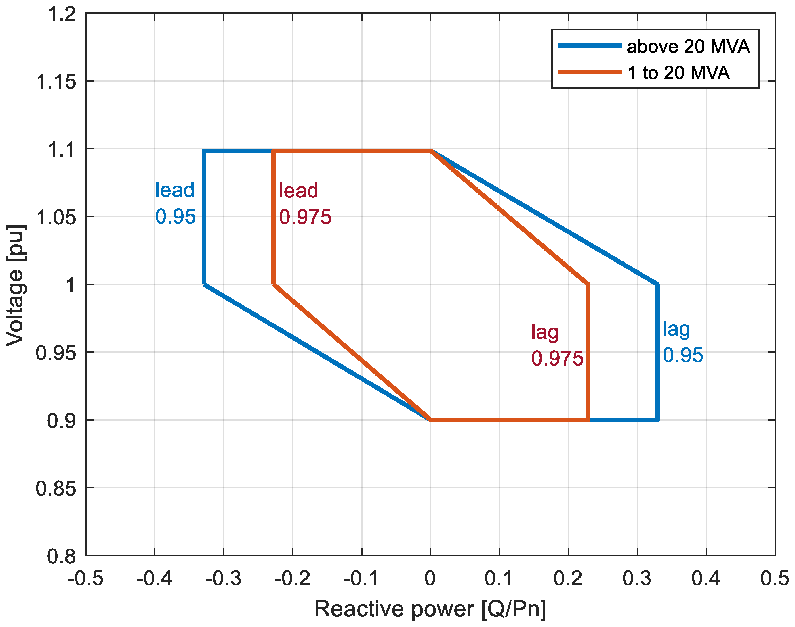
Figure 7. Reactive power and voltage control range requirements of γ and δ categories of RPPs.
Although the RPP can only operate within a reactive power tolerance range of not more than 5 percent of rated power, there is no requirement for reactive power capacity while operating below ±5 percent of rated power Pn (MW).
- 3.
-
RPPs of δ category
The ability to function in voltage, power factor, or reactive power control modes is required for this set of RPPs. The genuine control operational mode and the operating point must be approved by the DNSP. The RPP must be able to adjust reactive power support at the POC within the reactive power capability ranges depicted in Figure 6 where Qmin and Qmax are voltage dependent while operating between 5 percent and 100 percent of rated power Pn (MW). The required RPP reactive power capability at nominal voltage is shown in Figure 7. Although the RPP can only operate within a reactive power tolerance range of not more than 5 percent of rated power, as illustrated in Figure 6, there is no demand for reactive power capacity while running below ±5 percent of rated power Pn (MW).
- D.
-
Reactive Power, Power Factor, and Voltage Control
The below-mentioned conditions should be implemented in renewable power plants of γ and δ with a reactive power contract with a transmission utility:
-
The RPP must have both a voltage control function and reactive power control capabilities that allow it to manage the voltage as well as the reactive power it delivers at the POC.
-
One of the three functions—voltage, power factor, and reactive power—can only be employed at a time since the management of reactive power and voltage functions is often mutually exclusive.
-
The control function and relevant parameter values for the reactive power and voltage control functions, which will be carried out by the RPP, shall be specified by the distribution network system planner in conjunction with the regional control center and/or the system operator. The specified control functions shall be set out in the operating agreement.
- 1.
-
Reactive Power Control
Reactive power control, which is unrelated to active power and voltage, regulates the reactive power supply and absorption at the POC. The RPP must update its echo analog set point value within two seconds if the reactive power control set point is altered by the distribution network system planner, the Regional Control Center, and/or the system planner. The RPP must respond to the new set point within 30 s after receiving an order to change the set point. A maximum tolerance of 2 percent of the set point value or 0.5 percent of the maximum reactive power may exist between the accuracy of the accomplished control and the set point. Reactive power set points must be delivered to the RPP with a 1 kVAr degree of accuracy.
- 2.
-
Power Factor Control
Power Factor Control adjusts the reactive power in accordance with the active power at the POC. The RPP must update its echo analog set point value within two seconds in response to any changes made to the power factor set point by the regional control center, the system operator, and/or the distribution network system planner. The RPP has 30 s to respond to the new set point after receiving a second instruction to change it. The directed control’s accuracy and the set point’s precision cannot be more than ±0.02.
- 3.
-
Voltage Control
Through voltage management, the voltage at the POC is managed. After receiving the order to adjust the voltage set point, the change must start within 2 s and be finished within 30 s. According to droop characteristics, the control accuracy cannot deviate by more than two percent from the required reactive power injection or absorption. The voltage set point accuracy must be within 0.5 percent of nominal voltage. Each RPP must be able to conduct the control within the limits of its dynamic range and voltage range with the droop set up. In this application, droop is the voltage shift (p.u.) caused by a change in reactive power (p.u.). After the voltage control has reached the dynamic design constraints of the RPP, the control function must wait for likely overall control from the tap changer or other voltage control functions. Overall voltage coordination is the responsibility of the distribution network system planner, in collaboration with the regional control center and/or the system operator.
- E.
-
Power Quality
The RPP is responsible for monitoring power quality metrics (such as flicker, harmonics, and unbalanced voltages) and reporting to the distribution network system planner, Regional Control Center, and/or system operator, as needed. The RPP will use IEC standards to determine harmonics (IEC 61000-4-7 [5]) and flicker (IEC 61000-4-15 [6]). The IEC 61000-4-30 class A [7] power quality monitoring standard, which outlines methods for determining and interpreting power quality parameters in AC power supply systems, must be complied with by the RPP. The reporting will be undertaken to show that the POC is in compliance with the distribution network system planner requirements as outlined in the Purchase Power Agreement (PPA). The RPP at the POC must emit voltage and current quality distortion levels that comply with international standards such as IEC 61000-3-2:2018 [8].
Different practices and rules for harmonic control in electrical networks are specified in IEEE 519-2014 [9]. For integration and interoperability of distributed energy resources with associated power system interfaces, IEEE 1547-2018 [10] will be utilized. Communications systems and automation systems for power utilities will both utilize IEC 61850 [11]. Furthermore, the specified and established emission limit values must not be exceeded by the RPP’s design, setting, and execution. The DNSP will manage any excess voltage harmonic compatibility level induced by the network harmonic impedance at the POC, which is greater than three times the base harmonic impedance for the range of benchmark fault levels at the POC, in line with the licensing criteria for the DNSP. Equipment that will produce a resonance of more than three times at the POC at any frequency is not allowed to be connected by any RPP.
The continuity and voltage quality of the connection cannot always be guaranteed by the network operators under all conditions. As a result, the RPP must follow the different IEEE and IEC standards in order to safeguard the RPP facility from losses and/or damage brought on by various power quality problems. The RPP is also accountable for taking all necessary safeguards to protect the transmission and distribution networks.
In a distribution network with only home loads, harmonic distortion created by PV generators is below industry norms. Furthermore, if the photovoltaic generators are close to the transformer, harmonic distortion is reduced even further. Furthermore, the placement of photovoltaic systems adjacent to transformers aids in the management of voltage growth in distribution lines.
2.2. Protection and Fault Levels
To protect the RPP and maintain a reliable distribution system, protection mechanisms must be provided. The RPP must have the appropriate protective functions to safeguard itself from harm caused by distribution system faults and events. For RPPs of α and β in the and categories as well as bigger RPPs, the RPP must be capable of identifying islanded operation in all system configurations and shutting down power generation in such a condition within 0.2 s. Islanded operation with a portion of the distribution system is not authorized unless the distribution network system designer has expressly consented to it.
2.3. Active Power Constraint Functions
The distribution network system planner and the system operator may limit the active power output of RPPs larger than 100 kVA for system security considerations. Constraint functions, or additional active power control functions, assist prevent distribution system imbalances and/or overloading. Absolute production constraints, delta production constraints, and power gradient constraints are among the necessary constraint functions. The following sections give more information on each of these. For small hydro power plants, the power gradient and delta production constraints are not necessary.
2.4. Control Function Requirements
For different capacity RPPs, different control actions are required. For the RPP with a capacity between 100 kVA and 1 MVA, control functions such as constraint of absolute production and constraint power gradient are required. Furthermore, for the RPPs of capacities between 1 MVA and 20 MVA, control functions such as constraint of absolute production, constraint power gradient, reactive power control, power factor control, and voltage control are required. Lastly for the RPPs of capacities greater than 20 MVA, control functions such as the frequency control, constraint of absolute production, constraint of delta production, constraint power gradient, reactive power control, power factor control, and voltage control are required.
The numerous control functions’ objective is to guarantee that the RPP’s generation is under control and monitored at all times. The maximum MW per minute ramp rate set by the RPP control system should allow the distribution system planner and operator to govern the ramp rate of the active power output.
2.5. Ramp Rates
In particular, positive ramp rate during startup, positive ramp rate only during normal operating conditions, and negative ramp rate during controlled shut down are necessary for the ramp rate parameters to be valid throughout all operational categories. They should not be used to regulate frequency. The RPP control system must be able to manage the ramp rate of its Active Power output with a maximum MW per minute ramp rate set by the Regional Control Centre and/or the system operator. There are two possible maximum ramp speeds. The average MW ramp rate over a minute will be subject to the initial ramp rate setting. A 10 min averaged MW per minute ramp rate will be covered by the second ramp rate choice. Additionally, each of these ramp rate settings has to be individually changeable between 1 and 30 MW each minute. Different ramp rate properties must be met for each of the operational conditions, such as decreasing wind speed, cloudiness, or frequency deviation. The Solar Power Generating Plant’s power production must be reduced by 10% per minute, in any operational condition and from any working point, without cutting the RPP off from the network, to a maximum power value (target value), which may equate to a 100% decrease in power. The RPP operator, the regional control center, and/or the system operator must all agree on a procedure for setting and modifying the ramp rate control.
2.6. High Wind Curtailment
The wind power generating plant must remain connected to the distribution system when average wind speeds are below a preset cut-out wind speed. The cut-out wind speed must be at least 25 m/s based on the wind speed estimated as an average value over a 10 min period. In order to avoid a momentary halt of Active Power generation at wind speeds close to the cut-out wind speed, the Wind Turbine Generating Plant should be equipped with an automatic downward regulation mechanism.
The RPP Active Power must be able to be continuously reduced to a value between 100% and at least 40% of the rated power. Individual Wind Turbine Generating Plants are allowed to shut down while downward regulation is being applied in order to precisely follow the load characteristic.
There are two methods for downward control: continuous and discrete. Discrete regulation cannot have a step size more than 25% of the rated power in the space between the slanted lines in Figure 8’s example of a high wind downward control chart. When downward regulation is being used, individual wind turbine-producing plant units may be shut down. The downward regulatory band will be decided upon in conjunction with the system planner when the Wind Turbine Generating Plant units are commissioned.
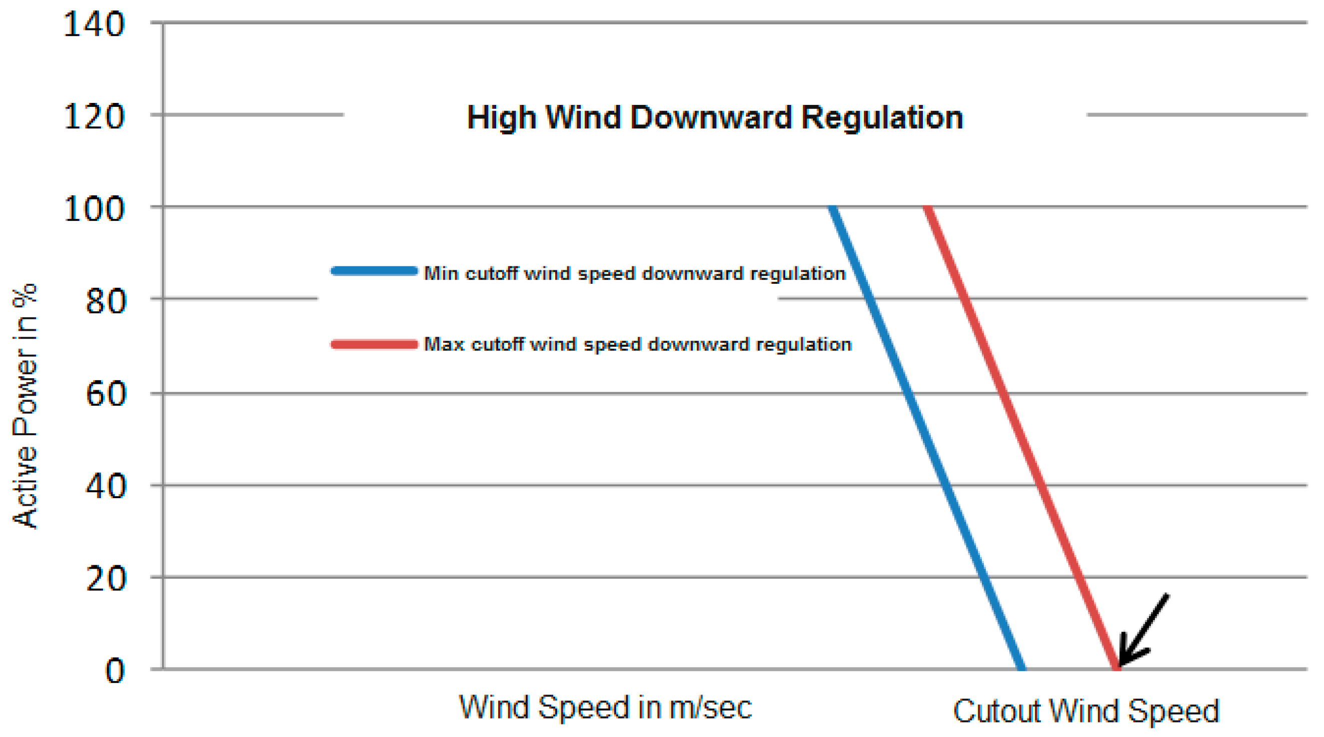
Figure 8. Illustrative High Wind Downward Regulation Chart.
2.7. RPP System Reserve Requirement
A greater requirement for various forms of reserves may result from the increased integration of wind and solar power as well as other RPPs to a lesser extent. They require larger operational and planning reserves because of the unpredictable nature of their output in order to offset the increased risk of being unavailable or going offline when they are needed. Additionally, they do not provide much inertia to the system, which makes it necessary to regulate frequencies more strictly and may call for higher levels of regulating and spinning reserve. For the purpose of calculating planned and operational bank reserves, several factors must be taken into account. RPPs must, overall:
- (a)
-
Within the design margins, maintain at least two separate set amounts of spinning reserve.
- (b)
-
Maintain the spinning reserve set level within 2% of the registered capacity with the DNSP, the regional control center, and/or the system operator for at least one hour.
References
- Khan, B.; Singh, P. The Current and Future States of Ethiopia’s Energy Sector and Potential for Green Energy: A Comprehensive Study. Int. J. Eng. Res. Afr. 2017, 33, 115–139.
- Ayetor, G.; Mbonigaba, I.; Sunnu, A.; Nyantekyi-Kwakye, B. Impact of replacing ICE bus fleet with electric bus fleet in Africa: A lifetime assessment. Energy 2021, 221, 119852.
- Singh, P.; Khan, B.; Alhelou, H.H.; Mahela, O.P. Impressions of remote area electrification on social and economic indicators. AIMS Energy 2020, 8, 1045–1068.
- Hailu, A.D.; Kumsa, D.K. Ethiopia renewable energy potentials and current state. AIMS Energy 2021, 9, 1–14.
- Gunther, E. Harmonic and interharmonic measurement according to IEEE 519 and IEC 61000-4-7. In Proceedings of the 2005/2006 IEEE/PES Transmission and Distribution Conference and Exhibition, Dallas, TX, USA, 21–26 May 2006; pp. 223–225.
- Chen, Y.Y.; Chang, G.W.; Lin, C.S. A digital implementation of IEC 61000-4-15 flickermeter. In Proceedings of the 2015 IEEE Power & Energy Society General Meeting, Denver, CO, USA, 26–30 July 2015; pp. 1–5.
- Legarreta, A.E.; Figueroa, J.H.; Bortolin, J.A. An IEC 61000-4-30 class a—Power quality monitor: Development and performance analysis. In Proceedings of the 11th International Conference on Electrical Power Quality and Utilisation, Lisbon, Portugal, 17–19 October 2011; pp. 1–6.
- IEC 61000-3-2:2018; Electromagnetic Compatibility (EMC)—Part 3-2: Limits—Limits for Harmonic Current Emissions (Equipment Input Current ≤ 16 A Per Phase). IEC: London, UK, 2018. Available online: https://webstore.iec.ch/publication/28164 (accessed on 6 January 2022).
- IEEE Std 519-2014; IEEE Recommended Practice and Requirements for Harmonic Control in Electric Power Systems. (Revision of IEEE Std 519-1992). IEEE: Piscataway, NJ, USA, 2014; pp. 1–29.
- IEEE Std 1547-2018; IEEE Standard for Interconnection and Interoperability of Distributed Energy Resources with Associated Electric Power Systems Interfaces. (Revision of IEEE Std 1547-2003). IEEE: Piscataway, NJ, USA, 2018; pp. 1–138.
- IEC 61850:2022; SER Series, Communication Networks and Systems for Power Utility Automation. IEC: London, UK, 2022. Available online: https://webstore.iec.ch/publication/6028 (accessed on 10 March 2022).
More
Information
Subjects:
Energy & Fuels
Contributors
MDPI registered users' name will be linked to their SciProfiles pages. To register with us, please refer to https://encyclopedia.pub/register
:
View Times:
3.2K
Revisions:
2 times
(View History)
Update Date:
08 Aug 2022
Table of Contents


Notice
You are not a member of the advisory board for this topic. If you want to update advisory board member profile, please contact office@encyclopedia.pub.
OK
Confirm
Only members of the Encyclopedia advisory board for this topic are allowed to note entries. Would you like to become an advisory board member of the Encyclopedia?
Yes
No
${ textCharacter }/${ maxCharacter }
Submit
Cancel
Back
Comments
${ item }
|
${ item.createdUser.fullName }
${ item.createdAt }
${ item.vote }
${ item.reply }
Delete
${ reply.createdUser.fullName }
${ reply.createdAt }
${ reply.vote }
Delete
There is no reply to this comment~
${ item.replyTextCharacter }/${ item.replyMaxCharacter }
Submit
Cancel
More
No more~
There is no comment~
${ textCharacter }/${ maxCharacter }
Submit
Cancel
${ selectedItem.replyTextCharacter }/${ selectedItem.replyMaxCharacter }
Submit
Cancel
Confirm
Are you sure to Delete?
Yes
No