Your browser does not fully support modern features. Please upgrade for a smoother experience.
Submitted Successfully!
 +1 credit
Thank you for your contribution! You can also upload a video entry or images related to this topic.
For video creation, please contact our Academic Video Service.
| Version | Summary | Created by | Modification | Content Size | Created at | Operation |
|---|---|---|---|---|---|---|
| 1 | Valda Rondelli | -- | 2786 | 2022-08-04 17:23:19 | | | |
| 2 | Rita Xu | Meta information modification | 2786 | 2022-08-05 04:39:53 | | |
Video Upload Options
We provide professional Academic Video Service to translate complex research into visually appealing presentations. Would you like to try it?
Cite
If you have any further questions, please contact Encyclopedia Editorial Office.
Rondelli, V.; Franceschetti, B.; Mengoli, D. Ground Autonomous Vehicles for Agriculture. Encyclopedia. Available online: https://encyclopedia.pub/entry/25863 (accessed on 11 July 2026).
Rondelli V, Franceschetti B, Mengoli D. Ground Autonomous Vehicles for Agriculture. Encyclopedia. Available at: https://encyclopedia.pub/entry/25863. Accessed July 11, 2026.
Rondelli, Valda, Bruno Franceschetti, Dario Mengoli. "Ground Autonomous Vehicles for Agriculture" Encyclopedia, https://encyclopedia.pub/entry/25863 (accessed July 11, 2026).
Rondelli, V., Franceschetti, B., & Mengoli, D. (2022, August 04). Ground Autonomous Vehicles for Agriculture. In Encyclopedia. https://encyclopedia.pub/entry/25863
Rondelli, Valda, et al. "Ground Autonomous Vehicles for Agriculture." Encyclopedia. Web. 04 August, 2022.
Copy Citation
The available autonomous ground platforms developed by universities and research groups that were specifically designed to handle agricultural tasks was performed. As cost reduction and safety improvements are two of the most critical aspects for farmers, the development of autonomous vehicles can be of major interest, especially for those applications that are lacking in terms of mechanization improvements.
precision agriculture
UGV
tractor
sensors
1. Introduction
Precision agriculture (PA) and autonomous vehicles are nowadays topics of increasing interest for the primary sector, as well as safety measures for the operator in the use of agricultural machines.
Agriculture is indeed one of the sectors that features the most deadly accidents every year [1][2][3], and tractors overturning is by far the most frequent cause of injury or death of the operator [1][2][3][4].
Autonomous/unmanned ground vehicles (AGVs/UGVs) represent a key factor in reducing the number of fatal injuries since they are able to operate without human intervention in real time and decrease driver actuation during normal operation in the field. Beyond serving as a solution to mitigate the risk related to farming activities, UGVs can help in contrasting the scarcity of human labor, both in terms of quantity and quality or required skill. Other strengths of UGVs can be recognized in terms of the timeliness of the execution and the precision and repeatability of the operations. Furthermore, an autonomous vehicle potentially operates for a longer time without being limited by safety regulations that are addressed to preserve human operator health (e.g., hours per working day with regard to daily vibration exposure to whole-body vibration at work). Safety is a primary issue for tasks involving agricultural machines, and in extreme soil conditions, it may be convenient to replace ride-on tractors with autonomous vehicles [5] to prevent the consequences of potential tractor overturns.
The beginning of PA is dated to the 1980s; nevertheless, the first prototypes of autonomous driving vehicles were designed about 30 years beforehand. PA aims toward defining the correct management for the homogeneous areas of the field, i.e., “doing the right thing, in the right place and in the right time” [6]. Both the spatial and temporal variabilities of all the factors affecting the whole crop production process are assessed and managed to improve input efficiency in dynamic crop management. Increasing efficiency means using less while preserving the same final result or obtaining a better output using the same amount of inputs [5][7]. In addition to the technical aspects, even the economic and environmental consequences need to be considered since the possibility of avoiding overlapping during any field operations (such as spraying and spreading) can significantly reduce the quantity of inputs and increase the working capacity, thus leading to a better environmental and economic sustainability.
In PA, the current deep interest in the development and implementation of autonomous driving systems is related to the need for relieving the operator of the two main aspects consequent to the driving action:
- -
-
The physical one, whereby using their movements and physical effort, the driver turns the steering wheel and operates levers and pedals to travel along the expected path;
- -
-
The mental one, whereby using their intelligence, the operator actuates the implements and needs continuous attention to perform the specific operation with all the maneuvers the task requires.
Indeed, in agriculture, the machine driver typically has two main tasks: driving the vehicle and managing the tools to guarantee an acceptable level of performance; this level has remained substantially unchanged over the decades [8]. While the operator tasks have been unchanged over this time, the design and features of both the tractors and the connected implements have changed greatly and the difficulties in driving and operating them in the field have increased, mainly for the aged operators. All this has motivated the current most advanced approach in PA, i.e., designing UGVs with artificial intelligence.
Since 1960, the UNIBO has been successfully engaged in this challenge. At the time, under the direction of Professor Giuseppe Stefanelli, two young researchers, namely, Pietro Bosi and Luigi Martelli, designed and prototyped the first programmable unmanned tractor, namely, “BOPS-1960” [9] (Figure 1).
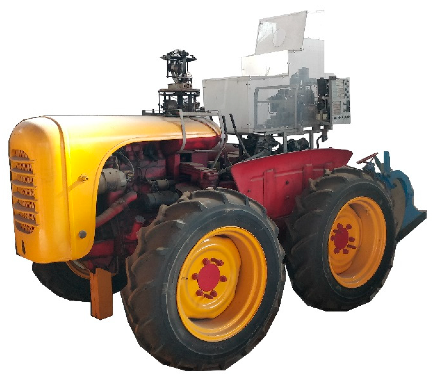
Figure 1. BOPS-1960, unmanned tractor.
Details and parts of the autonomous tractor were very well documented in some papers of the time, but these are not readily accessible, mainly because of the language barrier. With the BOPS-1960 being the first unmanned tractor developed in Italy and presented in local exhibitions of field-plowing operations, researchers considered it appropriate to recap its main features. Nevertheless, the current autonomous ground vehicles available on the market have dimensions, shapes and features that are different relative to the standard or narrow track tractors, and therefore, at least in the European countries, they are not identified as tractors under the current European regulations [10]. Consequently, they are mostly light platforms with a forward speed of less than 6 km/h, equipped with agricultural implements, and can be either specifically designed or commercial ones.
2. Research Activity on Autonomous and Robotic Ground Vehicles for Agricultural Tasks
2.1. Outside Europe
The first prototype to address was from Massey University (New Zealand). As described in Scarfe et al. (2009) [11], the prototype is an autonomous robotic four-wheel-drive platform that was designed to handle harvesting tasks in kiwifruit orchards. Fruit picking is achieved by means of four robotic arms mounted on the platform that are able to reach the fruit hanging above the vehicle (Figure 2).
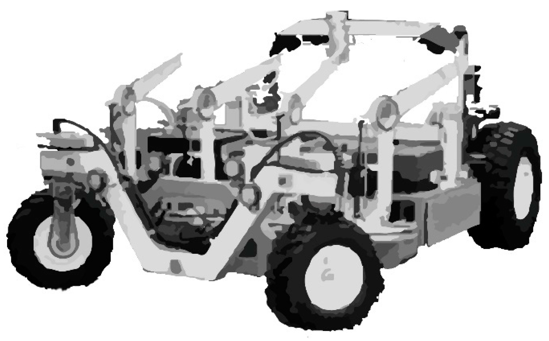
Figure 2. Sketch of the autonomous kiwifruit harvester.
This UGV is powered by a combustion engine that acts as a generator to power the hydraulic pump used for locomotion and steering. The arms use electrical motors and the control system algorithms are executed using two commercial dual-processor motherboards. The navigation and localization tasks rely on a differential global positioning system (GPS) receiver in synergy with a digital compass and a computer vision system. The vision system is also used to localize the fruit at harvesting time. The prototype has a total of 10 cameras. Two of them are dedicated to the navigation algorithms to enable obstacle avoidance features, six are used for fruit harvesting and the last two are used to monitor the stored fruits in the bins. The machine can operate continuously by monitoring both its status and the environmental conditions. The first algorithm is used to unload a full bin at the end of the row and automatically collect an empty one and autonomously go to the fuel refill station when needed. The second monitoring algorithm is used to pause the operations when wet conditions are detected and to control floodlights when needed.
Bangkok University (Thailand) developed a three-wheeled platform, with the two rear wheels driven by one 500 W DC motor per wheel (Figure 3). The purpose of the vehicle is the direct sowing of rice on a dried field. This autonomous vehicle consists of several sensors, such as a speed encoder/tachometer and a steering angle sensor, as well as the ability to calculate the overall traveled distance. Autonomous navigation is achieved using a proportional–integral–derivative (PID) controller for speed regulation and a proportional controller to control the steering angle. A GPS antenna and an inertial measurement unit (IMU) are used for the platform localization and attitude to enable waypoints or path following during navigation [12]. All the sensors feed information into an extended Kalman filter (EKF) to allow for precise position estimation of the overall system. The vehicle is able to follow a series of waypoints to enable autonomous seeding application over the field.
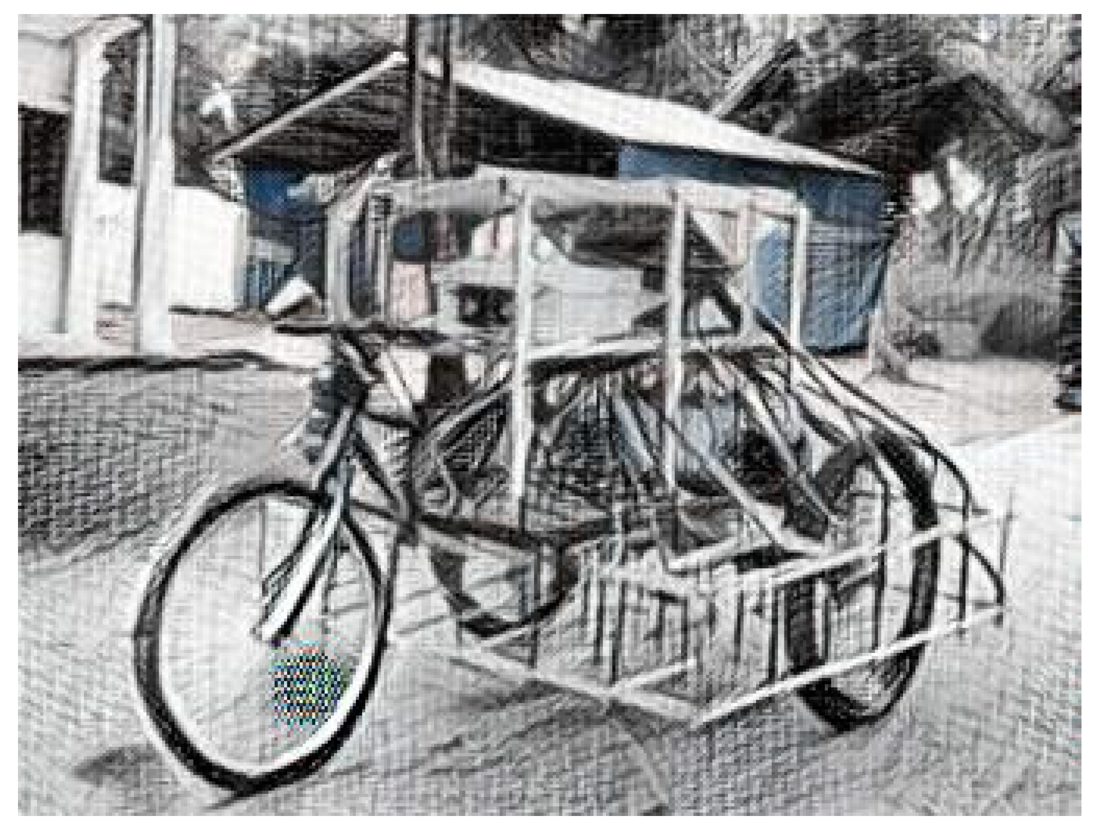
Figure 3. Sketch of the autonomous vehicle from Bangkok University.
The Australian Centre for Field Robotics (ACFR) at the University of Sydney designed a UGV platform named “Shrimp”. It is a multisensory platform that is able to efficiently detect, trace, localize and map single mango fruits in orchards.
The electric-powered vehicle is equipped with a color camera, a frame with stroboscope lights, 3D light detection and ranging (LiDAR) and a navigation system that relies on an inertial unit and a global positioning antenna (GPS/INS) (Figure 4) [13]. While autonomously traversing the orchard, the system is able to track and distinguish each fruit without overcounting by means of a multi-view approach. The navigation algorithm seems to rely mostly on the GPS/INS system.
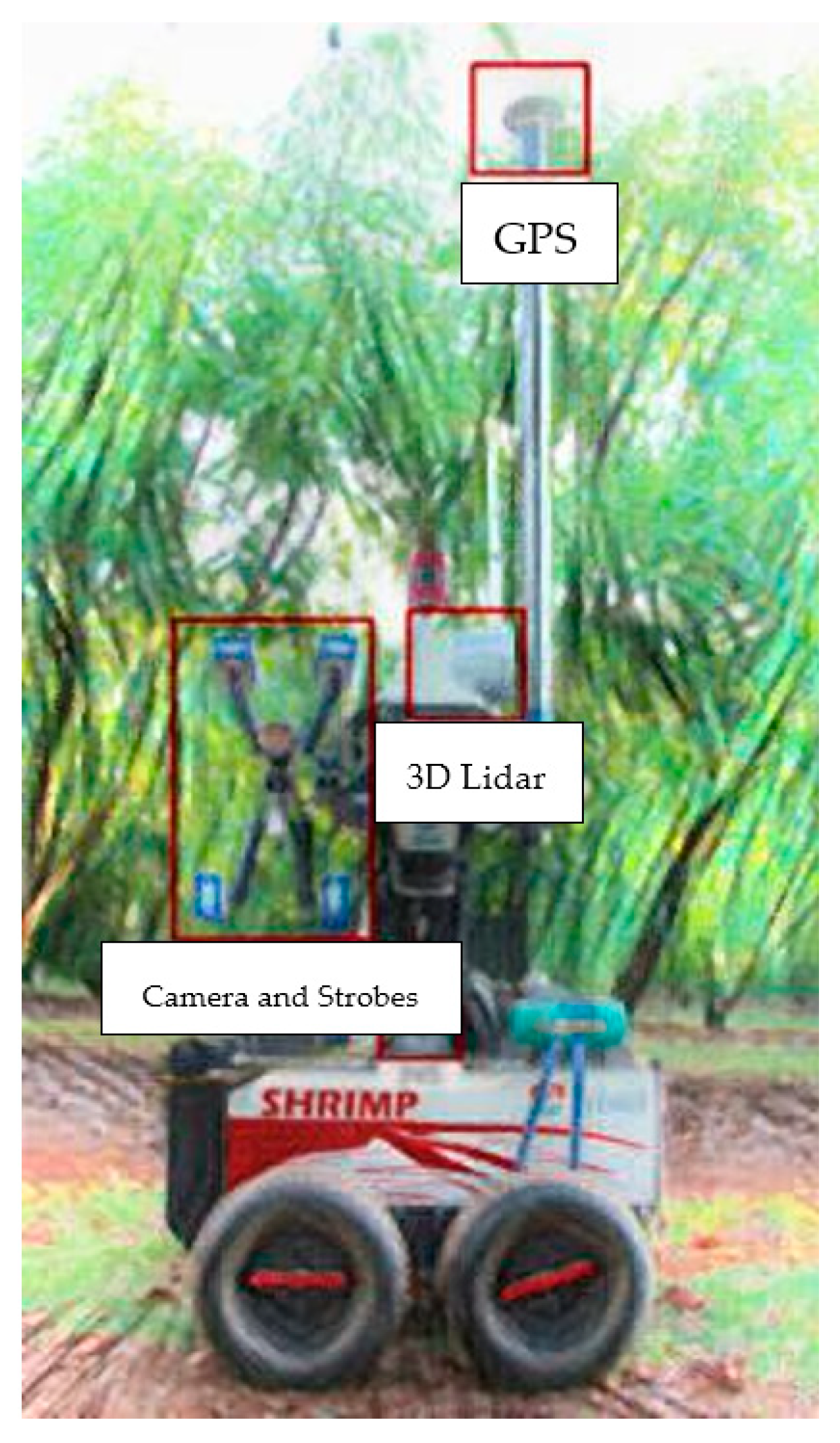
Figure 4. Sketch of the robotic platform “Shrimp” that was designed at the University of Sidney.
2.2. Within Europe
In Denmark (Aarhus University), a robust horticultural tool carrier named Hortibot, which was derived from an existing commercial machine, was developed by modifying a remote-controlled mower (Figure 5).
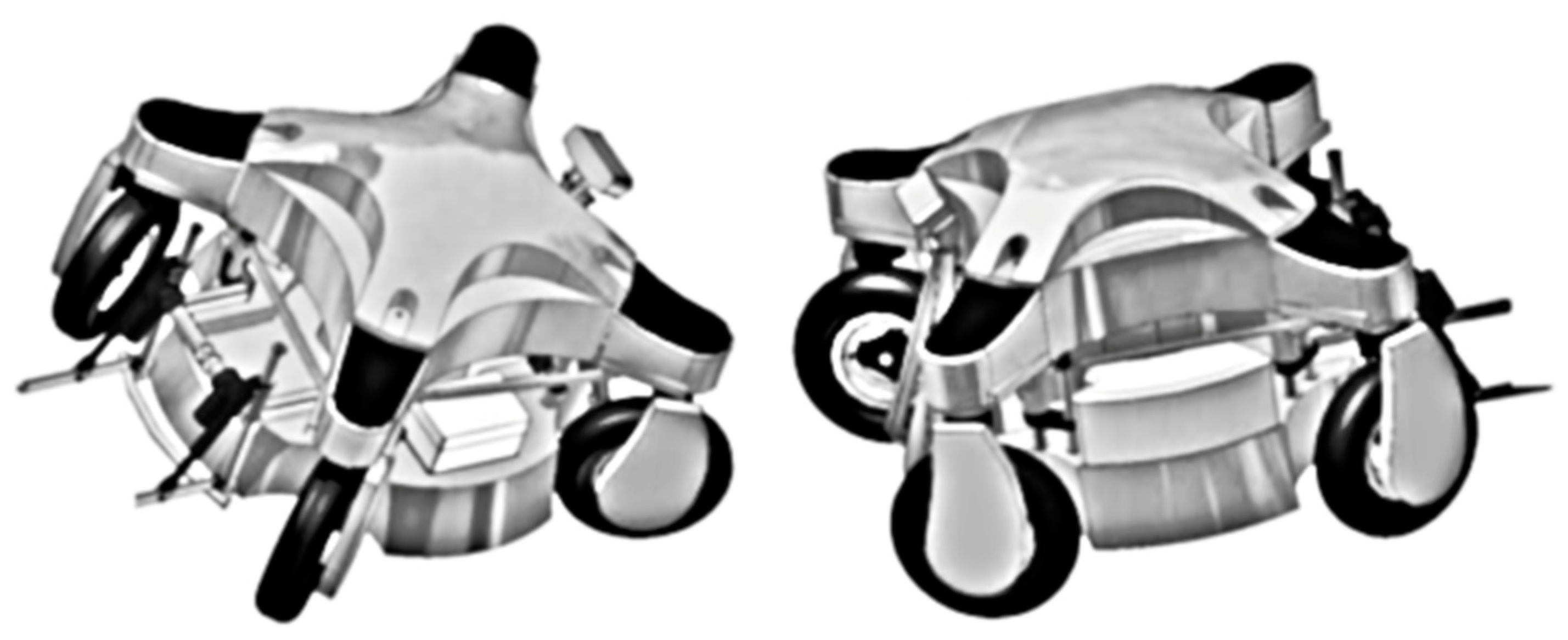
Figure 5. Sketch of the Hortibot platform with a 3D row vision system and lift arms.
The HortiBot is able to travel autonomously through several plots with visible rows by using a new commercial row detection system developed by Agrocom Vision (formerly Eco-Dan Inc., Kvistgaard, Denmark), which requires very low use of a GPS [14].
A feasibility study was carried out by Aarhus University and Vitus Bering University College Denmark to evaluate the viability of using the Hortibot mounted with weeding tools in farming operations. The performance was demonstrated through targeted performance that was adapted using knowledge of horticulture. The implemented tools for inter- and intra-row weeding consist of standard A-shaped hoes for inter-row weeding and with bed ridges attached to each end of the implement toolbar. The intra-row weeding is provided by finger and torsion weeders and pneumatic nozzles, which are all attached to five individual units carrying the A-shaped hoes. The pneumatic nozzles are switched on and off by electronically controlled pneumatic valves. Both the navigation control parallel to the rows and within rows are based on computer vision algorithms [15].
Two other research contributions were from Wageningen University (Netherlands). Both were designed for weed control in open fields: one for arable crops, specifically for addressing weed control in maize crops, and the other one was for weeding operations in pastures. The two platforms share a common four-wheel-drive locomotion approach and are powered by a diesel engine.
The first vehicle is able to autonomously control the weeds in a corn field using mechanical weeding elements fixed on the rear part of the vehicle. The vehicle can control the implements by exploiting the navigation data coming from the tractor in the seeding operation (Figure 6) [16]. The UGV autonomous navigation works by leveraging two GPS receivers and a base station for differential GPS (DGPS), and a real-time kinematic (RTK) correction signal is transmitted by means of a radio communication channel [17]. The platform control system is composed of two elements: a high-level controller made of two regulators and a low-level controller with a Smith predictor.
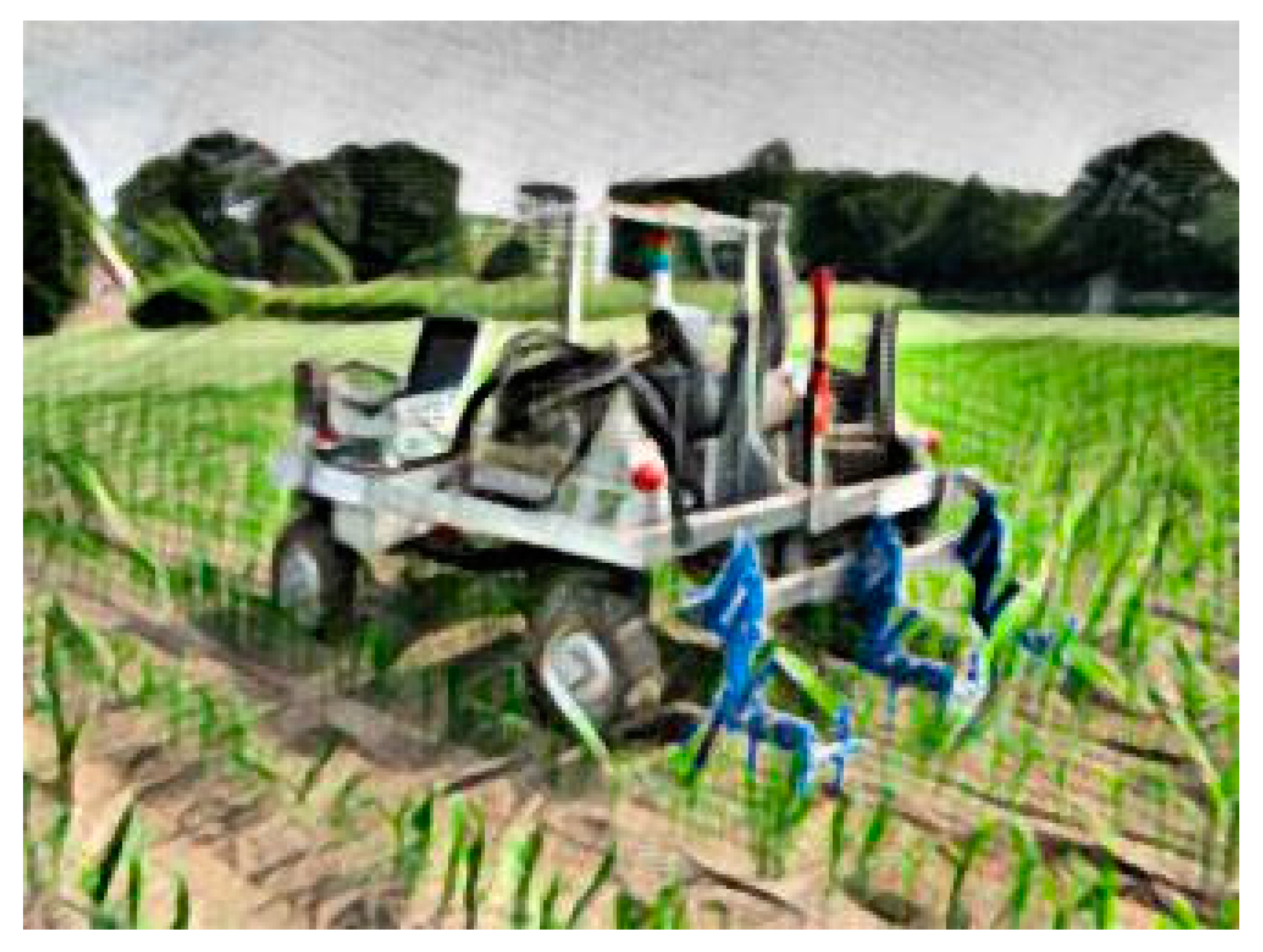
Figure 6. Sketch of the robot platform developed by Wageningen University in the field.
The second vehicle [18] is also equipped with a mechanical vertical axis weeding tool, but in this case, it is mounted on the front of the vehicle. The weeds are detected through computer vision algorithms that analyze the camera images. The camera is placed on a special arm that also holds the GPS antenna (Figure 7). The navigation system is very simple because, as the working scenario is set on meadows or pastures, the vehicle just needs to follow a predefined trajectory. As a safety measure and to ensure proper path following, the vehicle is designed to stop when the GPS signal is lost. Two levels of control are foreseen: a high-level controller is used to manage the navigation and path following, as well as perform the image processing and sending actuators commands; a low-level controller is used to manage sensors and hydraulics.
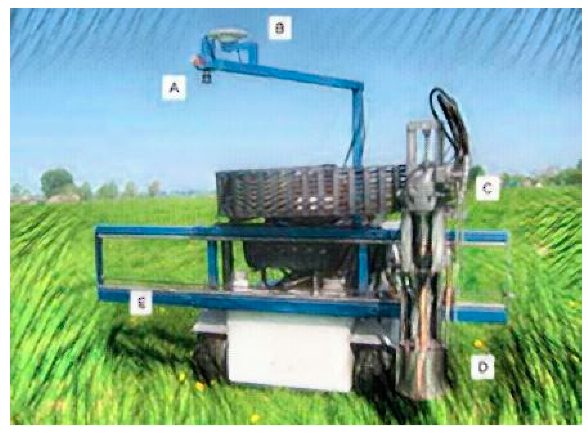
Figure 7. Sketch of the second robot vehicle developed by Wageningen University. Visible are (A) the camera, (B) the GPS antenna, (C) the hydraulic motor to actuate the weeder, (D) the weeder, and (E) the rail to adjust the weeder location.
Aarhus University (Denmark) also developed an autonomous application named GrassBots, which is a UGV that was designed to harvest herbaceous materials intended for biogas plants. The vehicle moves on two hydraulic tracks and is powered by a 74 kW diesel engine. The platform is 3 m wide and equipped with rotary encoders, an IMU and a global navigation satellite system (GNSS) antenna with an RTK localization system. The navigation is powered by open-source software specifically designed for unmanned systems.
GrassBots was designed to operate with very low human intervention and is able to autonomously cover all areas of the field safely and efficiently. A navigation algorithm defines the parallel lines (in terms of a set of waypoints) to follow on the field, its boundaries, obstacles, line widths, driving direction and end-of-field maneuvers [19].
The last UGV discussed here is Armadillo from the University of Southern Denmark, which is a field robotic tool carrier with a modular design to be configurable and adaptable to a wide range of precision agriculture research projects. Armadillo weighs around 425 kg and consists of two 18 × 80 cm footprint track modules, each with an integrated 3.5 kW electric motor, gear and motor controller. The track modules are mounted on the side of an exchangeable tool platform, which allows for an adjustable width and clearance height. The 48 V lithium power pack allows for 10 h of operation [20].
The Armadillo robot supports odometry feedback originating from a brushless motor hall sensor (625 ticks/meter) and is equipped with an IMU and RTK-GNSS receiver connected to the GPSnet.dk reference network.
The Armadillo robot is controlled using an industrial PC (dual-core, 2× GHz) running the open-source ROS-based FroboMind software platform developed by the University of Southern Denmark [21].
2.3. DEDALO: The Prototype from the University of Bologna
The Alma Mater Studiorum University of Bologna - Italy has recently developed the DEDALO UGV prototype, which was specifically designed for precision orchard and vineyard management (Figure 8).
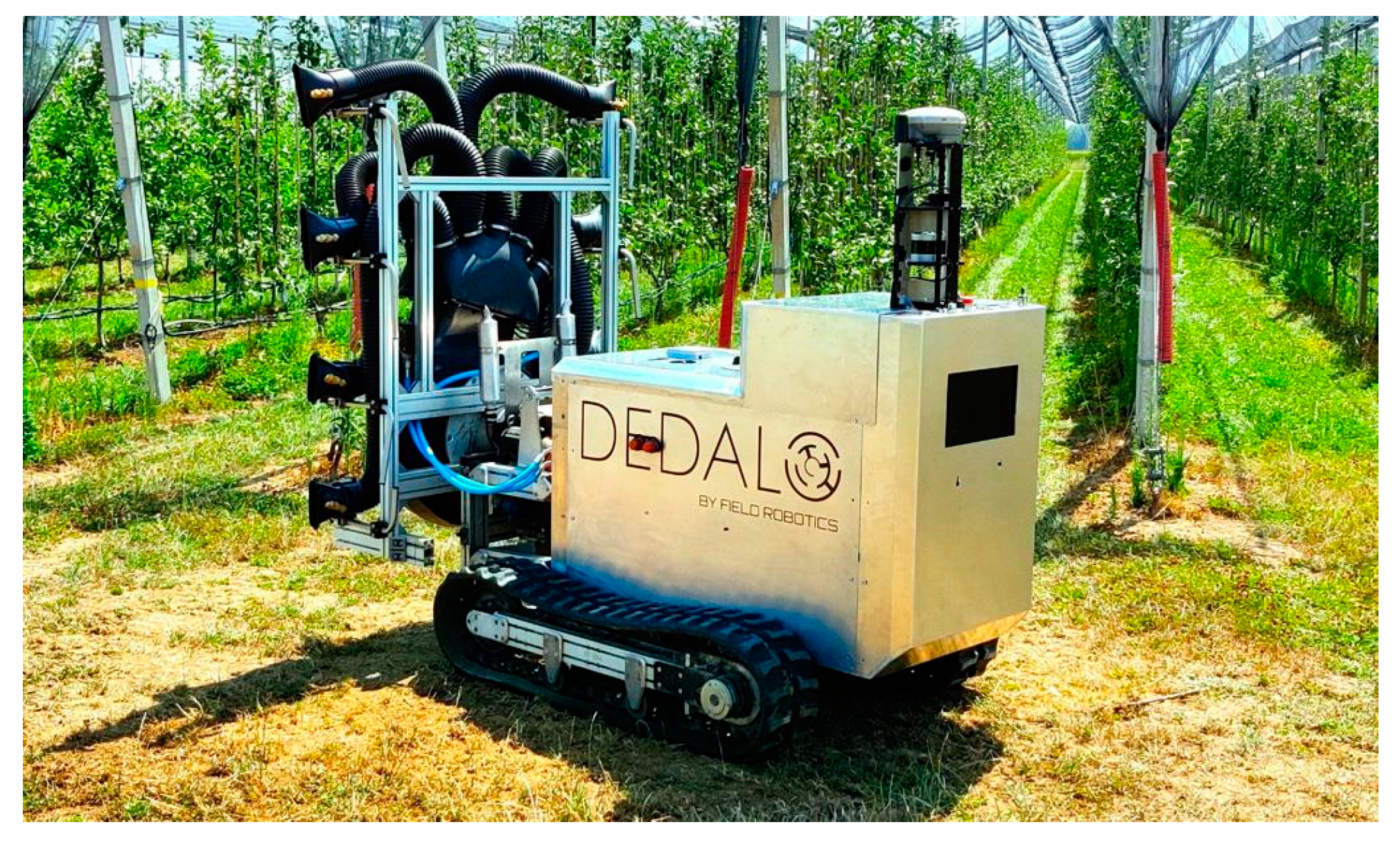
Figure 8. DEDALO, which is a UGV that was designed at the UNIBO in the last five years [22].
As reported in Mengoli et al. [22], this prototype is a small and lightweight structure that was designed for spraying and mowing operations in orchards and vineyards. The platform’s locomotion system is based on two rubber tracks and driven by electric motors, with the distance between the tracks being adjustable to match the row sizes. The mounted implements are powered by a 16 kW petrol engine due to the quite high energy demand of the attached implements (e.g., the sprayer).
The control logic of the UGV is divided into the following:
- -
-
A low-level (LL) controller;
- -
-
A high-level (HL) controller.
The LL component is directly connected to the vehicle actuators and motor drivers. It also oversees the safety procedures by transmitting velocity set-points to the electrical motors for locomotion while collecting useful telemetry data. The HL component contains the implementation of the navigation algorithms, and thus, it is the “smartest” element of the system. Using the information provided by the onboard sensors, autonomous navigation is provided in both open-field scenarios and in-row orchard scenarios.
The sensors fitted on the vehicle are as follows:
- -
-
Motor encoders for vehicle odometry;
- -
-
Nine-axis IMU, with integrated three-axis accelerometers, three-axis gyroscopes and three-axis magnetometers;
- -
-
A GNSS receiver for global localization, mainly in the open-field scenario;
- -
-
Three-dimensional LiDAR to estimate the surrounding obstacles, mainly for in-row navigation
Two computers (one for the LL control and the second for the HL control) process all the input/output signals and the control algorithms.
The locomotion electrical motors used to drive the platform rubber tracks are equipped with sinusoidal encoders to estimate the speed of the vehicle. An IMU evaluates the orientation of the platform in the 3D space by combining acceleration data, angular velocity and Earth magnetic field readings. To enable autonomous navigation of the platform in any operating scenario, two complementary elements were installed: the GNSS antenna and LiDAR. The GNSS receiver is a Trimble 8s system, (Raunheim, Germany) that is capable of receiving L1 and L2 signals and using differential correction from an authorized base station in the Trimble network. LiDAR (a 3D laser scanner, Velodyne Lidar Headquarters, San Jose, CA, USA) is used to perceive the environment and to detect the structural characteristics of the orchard and the non-negligible obstacles, such as fences. Two computers are used to split the computational burden of the HL logic from the LL logic, thus maintaining efficient low-level control, which is critical for the motion and the operation of the robot.
The communication and data transfer within the platform can basically be divided into the following:
- -
-
Communication between sensors and hardware;
- -
-
Communication between motor drivers and input/output (I/O).
To obtain optimal communication between sensors and hardware, a reliable communication channel supporting both the data flow and the low-latency commands to the actuators is used. Conversely, the CANbus protocol is used to connect the I/O subsystem and the motor drivers.
Finally, on the side of the vehicle opposite the implemented linkage system, a screen with a graphical interface was fitted to provide the user with information on the operation performed, the position of the robot and the telemetry data.
References
- Rondelli, V.; Casazza, C.; Martelli, R. Tractor Rollover Fatalities, Analyzing Accident Scenario. J. Saf. Res. 2018, 67, 99–106.
- Facchinetti, D.; Santoro, S.; Galli, L.E.; Pessina, D. Agricultural Tractor Roll-Over Related Fatalities in Italy: Results from a 12 Years Analysis. Sustainability 2021, 13, 4536.
- Myers, M.L.; Cole, H.P.; Westneat, S.C. Injury Severity Related to Overturn Characteristics of Tractors. J. Saf. Res 2009, 40, 165–170.
- Reynolds, S.J.; Groves, W. Effectiveness of Roll-over Protective Structures in Reducing Farm Tractor Fatalities. Am. J. Prev. Med. 2000, 18, 63–69.
- Casa, R. Agricoltura di Precisione: Metodi e Tecnologie per Migliorare L’efficienza e la Sostenibilità dei Sistemi Colturali, 1st ed.; Edagricole—New Business Media: Bologna, Italy, 2016; ISBN 978-88-506-5510-6.
- Gebbers, R.; Adamchuk, V.I. Precision Agriculture and Food Security. Science 2010, 327, 828–831.
- Bongiovanni, R.; Lowenberg-Deboer, J. Precision Agriculture and Sustainability. Precis. Agric. 2004, 5, 359–387.
- Wilson, J.N. Guidance of Agricultural Vehicles—A Historical Perspective. Comput. Electron. Agric. 2000, 25, 3–9.
- Stefanelli, G. La trattrice a programmazione senza pilota <BOPS-1960> nel quadro mondiale delle trattrici d’avanguardia. Macch. Mot. Agric. 1960, 9, 49–64.
- Regulation (EU) No 167/2013 of the European Parliament and of the Council of 5 February 2013, on the Approval and Market Surveillance of Agricultural and Forestry Vehicles. Available online: http://data.europa.eu/eli/reg/2013/167/oj (accessed on 10 June 2022).
- Scarfe, A.J.; Flemmer, R.C.; Bakker, H.H.; Flemmer, C.L. Development of an Autonomous Kiwifruit Picking Robot. In Proceedings of the 2009 4th International Conference on Autonomous Robots and Agents—ICARA, Wellington, New Zealand, 10–12 February 2009.
- Ruangurai, P.; Ekpanyapong, M.; Pruetong, C.; Watewai, T. Automated Three-Wheel Rice Seeding Robot Operating in Dry Paddy Fields. Maejo Int. J. Sci. Technol. 2015, 9, 403–412.
- Stein, M.; Bargoti, S.; Underwood, J. Image Based Mango Fruit Detection, Localisation and Yield Estimation Using Multiple View Geometry. Sensors 2016, 16, 1915.
- Jørgensen, R.; Sørensen, C.; Maagaard, J.; Havn, I.; Jensen, K.; Søgaard, H.T.; Sørensen, L. HortiBot: A System Design of a Robotic Tool Carrier for High-Tech Plant Nursing. CIGR J. Sci. Res. Dev. 2006, IX, 1–13.
- Sørensen, C.; Nørremark, M.; Jørgensen, R.; Jensen, K.; Maagaard, J.; Jensen, L. Hortibot: Feasibility Study of a Plant Nursing Robot Performing Weeding Operations—Part IV. In Proceedings of the 2007 ASAE Annual Meeting, Minneapolis, MN, USA, 17–20 June 2007.
- Bakker, T.; Van Asselt, K.; Bontsema, J.; Van Henten, E.J. Robotic Weeding of a Maize Field Based on Navigation Data of the Tractor That Performed the Seeding. IFAC Proc. Vol. 2010, 43, 157–159.
- Bakker, T.; Van Asselt, K.; Bontsema, J.; Müller, J.; Van Straten, G. A Path Following Algorithm for Mobile Robots. Auton Robot 2010, 29, 85–97.
- Van Evert, F.K.; Samsom, J.; Polder, G.; Vijn, M.; Van Dooren, H.-J.; Lamaker, A.; Van der Heijden, G.W.A.M.; Kempenaar, C.; van der Zalm, T.; Lotz, L.A.P. A Robot to Detect and Control Broad-Leaved Dock (Rumex Obtusifolius L.) in Grassland. J. Field Robot. 2011, 28, 264–277.
- Peças, P.; Fonseca, G.M.; Ribeiro, I.I.; Sørensen, C.G. Automation of Marginal Grass Harvesting: Operational, Economic, and Environmental Analysis. In Smart Farming Technologies for Sustainable Agricultural Development; IGI Global: Hershey, PA, USA, 2018; Available online: https://www.igi-global.com/chapter/automation-of-marginal-grass-harvesting/209548 (accessed on 1 April 2022).
- Jensen, K.; Nielsen, S.H.; Jørgensen, R.N.; Bøgild, A.; Jacobsen, N.J.; Jørgensen, O.J.; Jaeger-Hansen, C.L. A Low Cost, Modular Robotics Tool Carrier For Precision Agriculture Research. In Proceedings of the 11th International Conference on Precision Agriculture, Indianapolis, IN, USA, 15–18 July 2012.
- Jensen, K.; Laursen, M.; Midtiby, H.; Jørgensen, R. Autonomous Precision Spraying Trials Using a Novel Cell Spray Implement Mounted on an Armadillo Tool Carrier. In Proceedings of the XXXV CIOSTA & CIGR V Conference, Billund, Denmark, 3–5 July 2013.
- Mengoli, D.; Tazzari, R.; Marconi, L. Autonomous Robotic Platform for Precision Orchard Management: Architecture and Software Perspective. In Proceedings of the 2020 IEEE International Workshop on Metrology for Agriculture and Forestry (MetroAgriFor), Trento, Italy, 4–6 November 2020.
More
Information
Subjects:
Agricultural Engineering
Contributors
MDPI registered users' name will be linked to their SciProfiles pages. To register with us, please refer to https://encyclopedia.pub/register
:
View Times:
2.6K
Revisions:
2 times
(View History)
Update Date:
22 Aug 2022
Table of Contents


Notice
You are not a member of the advisory board for this topic. If you want to update advisory board member profile, please contact office@encyclopedia.pub.
OK
Confirm
Only members of the Encyclopedia advisory board for this topic are allowed to note entries. Would you like to become an advisory board member of the Encyclopedia?
Yes
No
${ textCharacter }/${ maxCharacter }
Submit
Cancel
Back
Comments
${ item }
|
${ item.createdUser.fullName }
${ item.createdAt }
${ item.vote }
${ item.reply }
Delete
${ reply.createdUser.fullName }
${ reply.createdAt }
${ reply.vote }
Delete
There is no reply to this comment~
${ item.replyTextCharacter }/${ item.replyMaxCharacter }
Submit
Cancel
More
No more~
There is no comment~
${ textCharacter }/${ maxCharacter }
Submit
Cancel
${ selectedItem.replyTextCharacter }/${ selectedItem.replyMaxCharacter }
Submit
Cancel
Confirm
Are you sure to Delete?
Yes
No