Your browser does not fully support modern features. Please upgrade for a smoother experience.
Submitted Successfully!
 +1 credit
Thank you for your contribution! You can also upload a video entry or images related to this topic.
For video creation, please contact our Academic Video Service.
| Version | Summary | Created by | Modification | Content Size | Created at | Operation |
|---|---|---|---|---|---|---|
| 1 | Sahan Bandara | -- | 2654 | 2022-08-02 03:32:41 | | | |
| 2 | Camila Xu | Meta information modification | 2654 | 2022-08-02 03:47:05 | | | | |
| 3 | Camila Xu | Meta information modification | 2654 | 2022-08-02 03:48:40 | | |
Video Upload Options
We provide professional Academic Video Service to translate complex research into visually appealing presentations. Would you like to try it?
Cite
If you have any further questions, please contact Encyclopedia Editorial Office.
Rajeev, P.; Bandara, S.; Gad, E.; Shan, J. Structural Assessment Techniques for In-Service Crossarms. Encyclopedia. Available online: https://encyclopedia.pub/entry/25749 (accessed on 24 June 2026).
Rajeev P, Bandara S, Gad E, Shan J. Structural Assessment Techniques for In-Service Crossarms. Encyclopedia. Available at: https://encyclopedia.pub/entry/25749. Accessed June 24, 2026.
Rajeev, Pathmanthan, Sahan Bandara, Emad Gad, Johnny Shan. "Structural Assessment Techniques for In-Service Crossarms" Encyclopedia, https://encyclopedia.pub/entry/25749 (accessed June 24, 2026).
Rajeev, P., Bandara, S., Gad, E., & Shan, J. (2022, August 02). Structural Assessment Techniques for In-Service Crossarms. In Encyclopedia. https://encyclopedia.pub/entry/25749
Rajeev, Pathmanthan, et al. "Structural Assessment Techniques for In-Service Crossarms." Encyclopedia. Web. 02 August, 2022.
Copy Citation
Crossarms are widely used in power distribution and telecommunication sectors to support overhead cables. These structures are horizontally attached to the top of vertically erected utility poles and are essential elements in connecting overhead cables to the poles. Timber is the dominantly used material type for crossarms in the existing distribution networks. Timber is selected for crossarms over the alternative materials (e.g., steel, composites, and concrete) due a number of relative advantages, of which higher strength-to-weight ratio, long service life, excellent insulation properties, economical, and renewable aspects are the main factors.
condition assessment
non-destructive testing
decay
failure analysis
1. Introduction
Timber elements such as utility poles and crossarms are extensively used in power distribution networks in Australia and around the world. Pandey et al. [1] reported that there are more than 40,000 timber H frames supporting around 7000 km of 115 kV transmission lines alone in the province of Ontario, Canada. In the United States, there is an estimated amount of over 100 million timber poles supporting electrical transmission and distribution systems. All these poles are connected to one or more crossarms [2]. In the North American countries, Douglas fir is the widely used timber species for crossarms [3]. In the Australian context, there is an estimated amount in excess of 5 million timber poles privately owned by the power distribution companies [4]. About 40 to 50 million dollars are annually spent for the maintenance and management of these assets by the Australian power industry [5].
Timber is selected for crossarms over the alternative materials (e.g., steel, composites, and concrete) due a number of relative advantages, of which higher strength-to-weight ratio, long service life, excellent insulation properties, economical, and renewable aspects are the main factors. Nevertheless, as a biodegradable material, deterioration of timber is inevitable due to the sources of weathering, decay, and termite attack [6]. The cyclic nature of wet and dry conditions, exposure to high and low temperatures, and direct exposure to sunlight causes weathering, which results in the degradation of wood surface [7]. Wood decay is also caused by fungal attack, which is a result of the interaction between organisms that utilise timber as a source of food for their growth [8]. Termite attack is not very common for timber crossarms given the location of these structures, typically about 8 to 15 m from the ground level. The deterioration processes can lead to reduction of the cross-sectional area of crossarms, change of timber material properties, splitting, and wood cell erosion. Figure 1 illustrates the deteriorated and failed timber crossarms subjected to the aforementioned causes. Flexure-induced splitting was observed in the majority of the crossarms. It is evident that most of the crossarms have failed or initiated the failure close to the location of end bots, which are supporting the insulators. Additionally, some failures can be observed at the vicinity of king bolt located at the centre of a crossarm, which is connecting the crossarm to the pole. The primary reason for this is the retention of moisture in bolt holes and the reduction in effective cross-sectional area of the crossarm due to the presence of the opening for the bolt to run through.
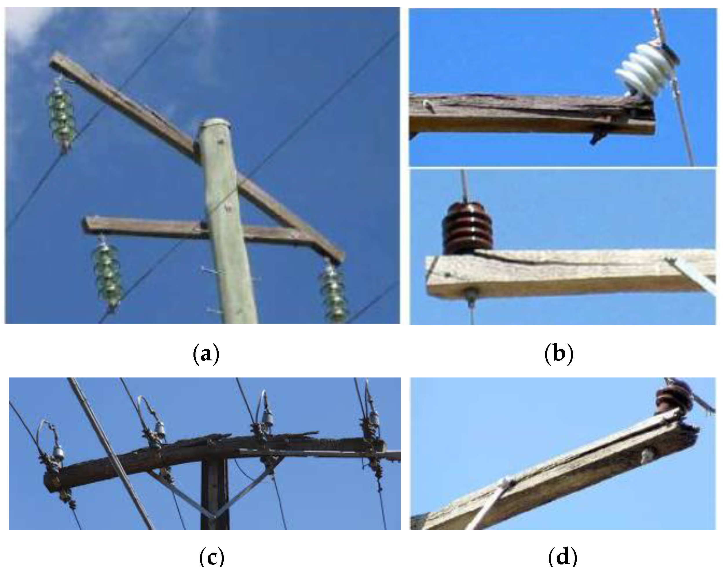 Figure 1. Deteriorated and failed timber crossarms due to decay and aeolian vibrations; (a) failed crossarm losing an insulator; (b) splitting at the end bolt locations; (c) badly split crossarm along the length; (d) losing sound wood at the end of the crossarm.
Except for the decay in crossarms, loosely connected king bolts and end bolts lead to enlargement of the bolt holes due to aeolian vibration. Alternating lift and drag forces induced by wind generate vibrations of overhead cables and these subsequently affect the crossarm connections. Improper bolted connections of the crossarms have a substantial effect of these vibrations initiating bolt hole enlargement. Continuation of the vibrations results in rapid progression of the bolt hole enlargement, which supports the retention of moisture and, thus, accelerated decay rates. Further, additional structural connections to crossarms exceeding the design specifications can be commonly observed in power distribution networks. Excessive load resulting from additional connections exceeding the design load can increase the probability of sudden crossarm failure without prior indications. The effects of these causes on timber crossarms are amplified, as wood is a natural material consisting of imperfections such as knots, splits, and slope of grain.
An accurate estimation of the remaining service life of crossarms is crucial for timely replacements that can avoid failures. Therefore, different condition assessment techniques are implemented in the field, considering the aspects of simplicity (ease of operation), accuracy, reliability, and safety of the operator. The conventional crossarm inspection techniques include visual inspection and sounding. However, given the subjective nature of these assessment techniques, more attention is paid towards the advancements in non-destructive testing (NDT) methods, which can eliminate the subjectivity and provide accurate results [9]. More focus on NDT techniques for timber structures are on stress wave propagation, ultrasonic pulse velocity, vibration-based techniques, and tomography techniques (e.g., [10][11][12]). The stress wave propagation technique is based on generation and propagation of either a longitudinal or transverse stress wave within the structure. Reflection patterns of the wave behaviour can be analysed to identify potential defects [13]. In the ultrasonic pulse velocity technique, the time-of-flight method is utilised to determine the wave propagating speed, and this speed is generally used to comment on the condition of the tested structure [14]. Vibration measurements are obtained in vibration-based techniques to correlate the strength with derived vibration properties and then to access the structural integrity. Tomography techniques provide local condition assessment by scanning the structure at selected locations and by evaluating the density [15]. In addition to NDT techniques, flexural behaviour of crossarms is also investigated via laboratory experiments to understand the performance of intact and deteriorated crossarms belonging to different species.
2. Decay of Timber Crossarms and Decay Identification
The decay is caused by fungal attack, and different timber species possess different inherent resistance levels for decay. In Australia, three types of fungus are identified, namely, brown rot, white rot, and soft rot. This categorisation is based on the chemical components of wood which they are attacking and the colour of infested wood [16]. Wang et al. [17] investigated the decay rates and identified that there is a difference in the decay rates even across a cross-section of a timber log. For untreated timber, sapwood indicated the highest decay rate in comparison with inner and outer heartwood. When sapwood was treated, it had a lower decay rate compared to heartwood. Therefore, the treatment process has substantial effects on the decay of crossarms. For the preservative treatment of timber, copper chromium arsenate (CCA), alkali copper quaternary (ACQ), and creosote can be used.
Retention of moisture on the bolt holes and the top surface of crossarms is identified as a major cause for increased decay rates. Khalid et al. [18] explored the capability of decay detection in wooden crossarms by implementing the microwave reflection method. The crossarms were categorised into three distinct groups, such as severe decay, incipient decay, and sound wood. This categorisation was based on the amount of moisture that can be absorbed by wood and the density of wood based on different decay stages. Results indicated that the proposed method was able to measure the defective area up to 2 cm from the surface of wood. Further, Khalid et al. [19] investigated the applicability of ultrasonic techniques to find a suitable method of measurement to determine the decay under the connecting metal blocks. For this ultrasonic pulse velocity method, the time-of-flight method was employed in the analysis to assess the condition of the crossarm. With the increase of the degree of defect, ultrasonic wave traveling times were observed to be increasing. Thus, the ultrasonic wave transit time was an indirect measurement providing the presence and degree of decay in wooden crossarms.
The remaining strength of a crossarm is directly related to the degree of surface decay. Ho et al. [20] developed a statistical model which correlates the amount of surface deterioration to the remaining strength of rectangular Douglas fir crossarms. An image processing technique was employed to accurately quantify the amount of deterioration. The image processing technique could overcome the subjectivity involved in the conventional visual inspection technique. It was identified that the decay in a high-stress zone has a prominent influence on the loss of strength compared to the decay in a low-stress zone. The high-stress zone of a crossarm was chosen as 1 ft from each side of the pole support. In addition, it was noticed that the presence of natural imperfections such as knots and slope of grain affected the remaining strength of a crossarm.
3. Flexural Strength of In-Service Crossarms
Timber, as a natural material, inherits imperfections and growth defects. Some of these are the slope of grain and presence of knots, splits, and checks. Standards specify the requirements and guidelines to be considered when selecting suitable timber for crossarms (e.g., [21][22][23]). These standards specify limits for the allowable knot size, slope of grain, checking, splitting, and presence of other defects. Researchers have paid attention to investigating the flexural strength of crossarms by conducting bending tests. Different species of wood, different crossarm geometries, effect of strengthening techniques, and effect of decay and knots are explored in terms of the bending capacity. Three-point and four-point bending tests are conducted for full-scale crossarms, or sometimes only for the critical regions of crossarms, to determine the bending strength parameters, such as modulus of rupture (MOR) and modulus of elasticity (MOE). A summary of the studies on flexural strength assessment of timber crossarms is presented in Table 1.
Table 1. Studies that examined the flexural strength of timber crossarms.
| Study | Crossarm Dimensions, Species, Number of Specimens Tested and Remarks |
Results and Remarks (Mean Values of MOR, MOE) |
|---|---|---|
| [3] | 89–114 mm and 95–120 mm, Douglas fir. | Southern Pine: MOR 75.9 MPa, MOE 13.8 GPa. |
| 89–114 mm and 95–120 mm, Southern Pine. | Douglas fir: MOR 63 MPa, MOE 15 GPa. | |
| 35 specimens of 2.4 m span. | Southern Pine: MOR 75.9 MPa, MOE 13.8 GPa. | |
| [24] | 95–120 mm, 2.5 m span. | Piquia: MOR 69.9 MPa, MOE 10,580 MPa. |
| 5 species were tested with 60 specimens per species. | Tauari Vermelho: MOR 59.2 MPa, MOE 7650 MPa. | |
| [25] | Circular crossarm specimens of average diameters of 18.5, 22.2, 25.2, and 27 cm, 9.1 m span. Western Red Cedar: 7 specimens. Northern White Cedar:11 specimens. Jack Pine: 26 specimens. |
Western Red Cedar: average strength 32.8 MPa. Northern White Cedar: average strength 28.9 MPa. Jack Pine: average strength 33.3 MPa. Red Pine: average strength 40.5 MPa. |
| [26] | 89–114 mm, 2.44 m span. Southern Pine: 60 specimens. Douglas fir: 60 specimens. Compared the flexural strength parameters with previous findings of [3]. |
Southern Pine: MOR 70.5 MPa, MOE 13.4 GPa. Douglas fir: MOR 59.8 MPa, MOE 13 GPa. Comparison of strength parameters over a 20-year interval showed that these parameters have reduced due to silvicultural processes and other changes. |
| [27] | 93.8–118.8 mm, Douglas fir, 250 specimens, span 2.4 m. Tested both rejected (according to specifications) and intact crossarms. 200 rejected specimens and 50 accepted specimens. |
Accepted specimens: MOR 76 MPa, MOE 7537 MPa. Rejected specimens: MOR 65 MPa, MOE 6715 MPa. Most of the rejected specimens (due to presence of knots) illustrated higher MOR than the requirement in American standard specification. |
| [28] | Tests were carried out to evaluate the strength enhancement via glass-fibre-reinforced polymer wrap (GFRP). Circular crossarm specimens with diameter 229–286 mm, 3.2 m span, 3 reference specimens, 3 specimens strengthened with GFRP (wrap thickness 0.6 m and 1.2 m), and crack-filled surface preparation. |
Reference specimens: MOR 28 MPa. Strengthened specimens: MOR 39.9 MPa. GFRP wrapping had substantial improvements in the flexural strength. |
| [29] | Tests were carried out to compare the bending strength of laminated specimens with solid sawn specimens. 89–114 mm and 95–120 mm, 3 different spans of 2.1, 2.4, and 3 m, Douglas fir. 10 specimens—solid sawn timber. 10 specimens—vertically laminated. 27 specimens—horizontally laminated. |
Solid sawn specimens: MOR 60.1 MPa. Vertically laminated specimens: MOR 50.6 MPa. Horizontally laminated specimens: MOR 46.9 MPa. 5 horizontally laminated specimens and 1 vertically laminated specimen failed at finger joint location. Laminated crossarms can reach the strength specifications for solid sawn crossarms under proper quality control. |
Some of the previous studies have neglected the way in which the crossarm is connected to the utility pole and the connection of the crossarm to the overhead cables. Figure 2 illustrates a single crossarm and double crossarm assembly presented in [30]. A 20 mm bolt, typically called the king bolt, connects the crossarm to the utility pole and a gain block is placed in between to have a strong connection. This connection detail needs to be replicated in the bending test setup. Schematic representation of the three-point bending setup is illustrated in Figure 3a and the actual test setup is shown in Figure 3b. Vertical supports are provided at around 100 mm from the two ends of the crossarm specimens. Researchers carried out three-point bending tests for 110 decommissioned timber crossarms collected around various parts of Victoria, Australia. These specimens were from three different power distribution networks. A king bolt was placed at the middle and a displacement-controlled load was applied, according to the Australian standard specifications. Breadth of the rectangular specimens ranged from 85 to 125 mm and the height range was 70 to 155 mm. Test spans varied from 1.7 to 2.5 m, depending on the crossarm geometry, and the bolt sizes were 20, 25, and 30 mm. Tested specimens were from different species belonging to both softwood and hardwood.
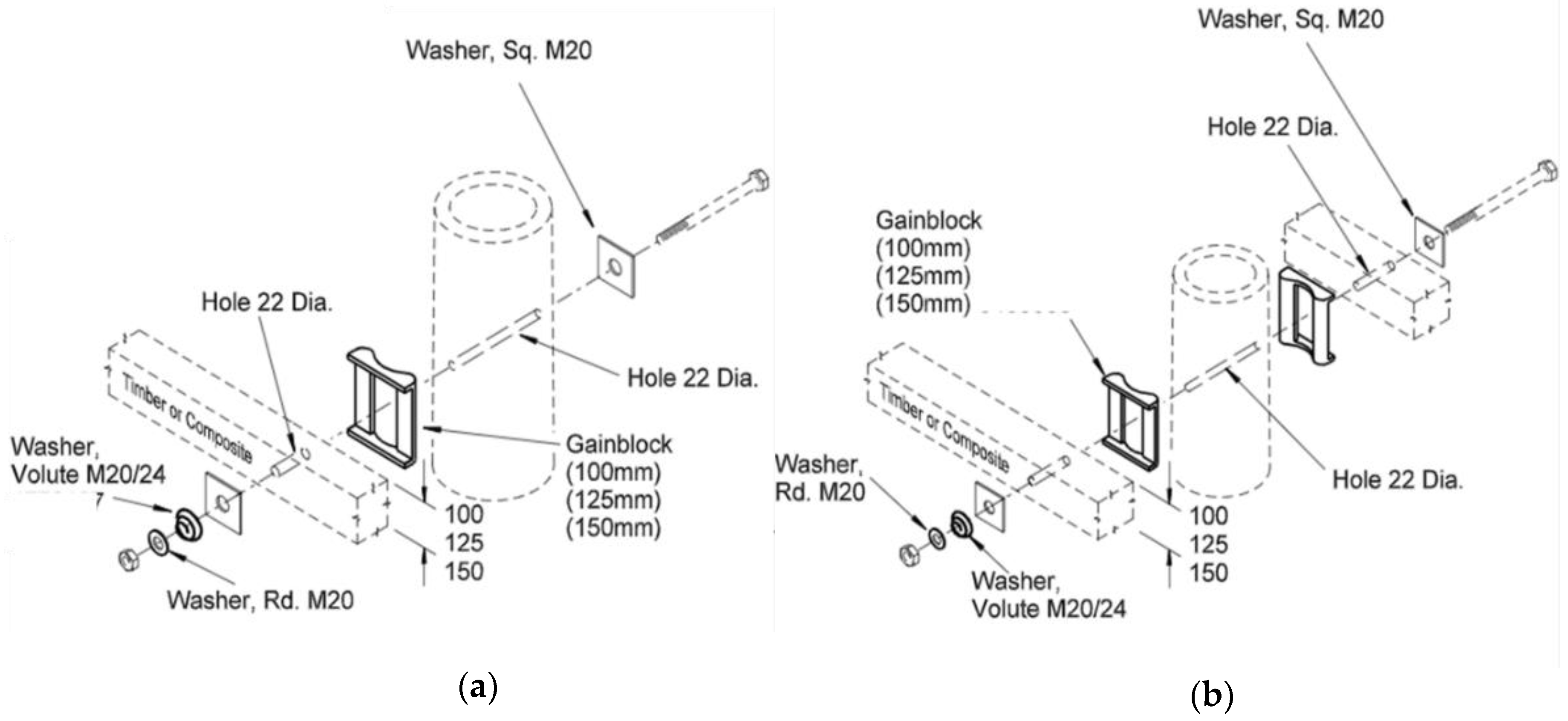 Figure 2. Predrilled crossarm assembly: (a) single crossarm; (b) double crossarm [30].
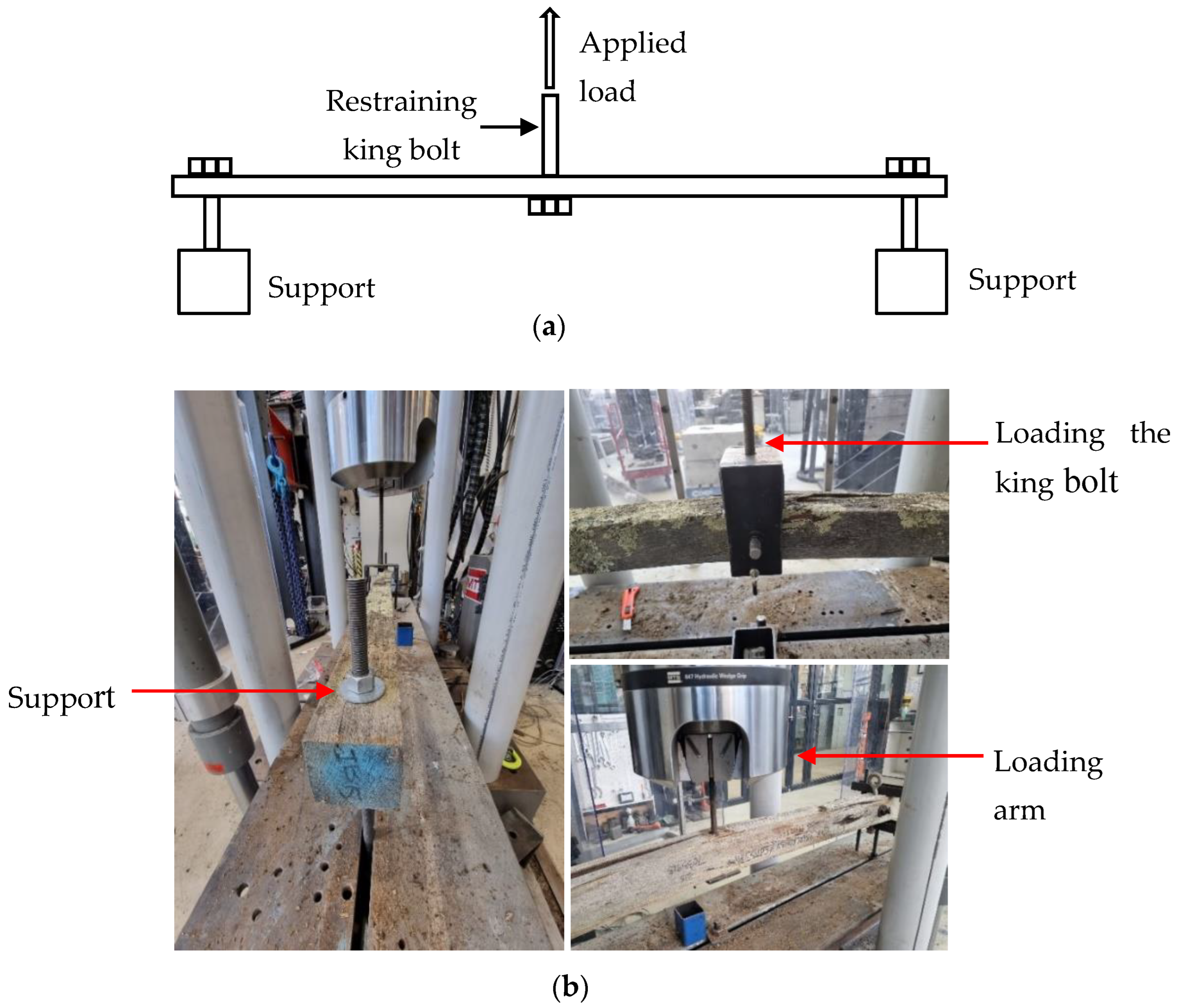 Figure 3. Three-point bending test setup: (a) schematic representation; (b) actual test setup.
Figure 4a illustrates the cumulative frequency distribution of the MOR for the tested crossarms. The MOR indicates the failure flexural strength of tested specimens. The failure load was recorded from the experiments for each specimen to calculate the failure moment. The section moduli of crossarms were calculated using the measured breadth and height. Then, the simple bending theory was used in calculating the MOR with the use of failure moment and the section modulus. From the visual examination before the testing, crossarms were observed having light, moderate, and severe degradations. Therefore, a significant variation of the MOR can be observed, as evidenced in Figure 4a. When a crossarm is subjected to deterioration, the material properties, such as density and MOE, can degrade, leading to reduced fibre strength. In addition, deterioration can result in loss of sound wood, reducing the effective section modulus. This depletion is substantial if the loss of sound wood is from the exterior of the crossarm rather than from the interior, since loss of material at the perimeter of the cross-section will have the highest reduction in the section modulus. The highest and lowest MOR were 123 and 2.1 MPa, respectively. The average MOR for the tested 110 crossarms was 52.5 MPa. Except for the degree of deterioration of a crossarm, the species of wood belonging to softwood or hardwood and its strength grading directly affected the bending strength indicators. Bending tests were carried out using condemned crossarms from service and finding a relatively large number of crossarms from the same timber species is practically challenging. Thus, the influence of timber species on the calculated MOR cannot be avoided when interpreting the results. Figure 4a indicates that ~50% of the tested poles had MOR values lower than 50 MPa. Figure 4b denotes that about 35 crossarms showed MOR above 60 MPa, which corresponds to light deterioration. These crossarms with a MOR above 60 MPa can still be used in the field, although they have been condemned. This reflects the inaccuracy of the current practices in the condition assessment: specifically, misdiagnosing the defects. Critical region of the crossarms was found to be around the king bolt where the highest stresses are present. The calculated MOR values for the tested specimens can be used to benchmark the health ratings of inspectors to improve the visual examination rating system. Visual examinations were carried out by inspectors before condemning the tested crossarms. Thus, each tested crossarm possesses visual examination results and health ratings based on the examination. Once bending tests are carried out, flexural strength of each crossarm is determined, and subsequently, the health rating of inspectors can be benchmarked. If a particular crossarm with a good health rating from visual inspection is providing a lower MOR from bending tests, it indicates that the visual examination has overlooked defects. When it is the other way around, it indicates that the visual examination has misdiagnosed defects.
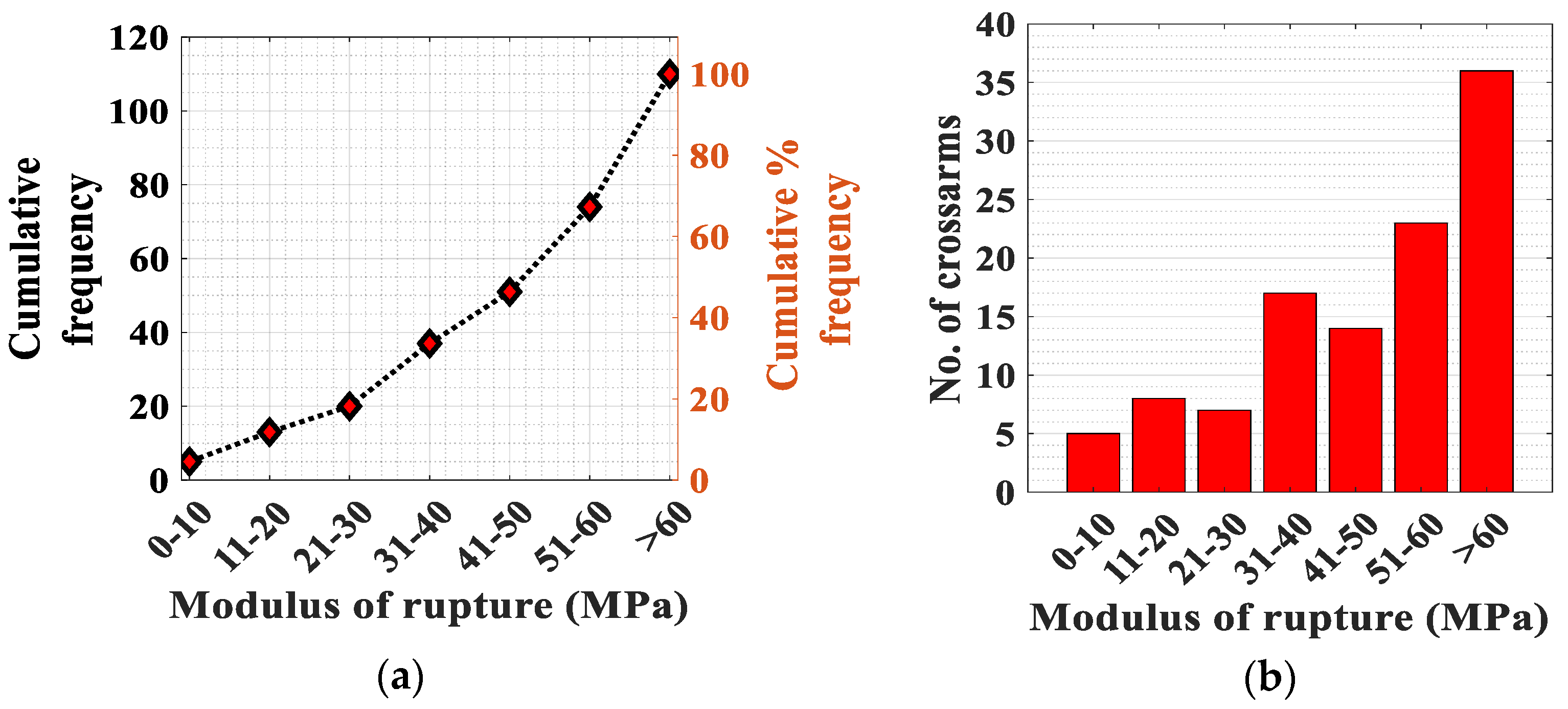 Figure 4. (a) Variation of the modulus of rupture—110 specimens; (b) groupings of the modulus of rupture.
References
- Pandey, M.D.; Ho, V.; Bedi, S.; Woodward, S.B. Development of a condition assessment model for transmission line in-service wood crossarms. Can. J. Civ. Eng. 2005, 32, 480–489.
- Wolfe, R.; Moody, R. Standard Specifications for Wood Poles, Forest Products Laboratory; US Department of Agriculture: Washington, DC, USA, 1997.
- Barnes, H.M.; Winandy, J.E. Bending properties of wooden crossarms. In Proceedings of the American Wood Preservers’ Association, Fort Lauderdale, FL, USA, 15–17 May 2001; Volume 97, pp. 30–38.
- Francis, L.; Norton, J. Australian Timber Pole Resources for Energy Networks. A Review; Department of Primary Industry and Fisheries, Queensland Government: Brisbane, Australia, 2006.
- Nguyen, M.; Foliente, G.; Wang, X.M. State-of-the-practice & challenges in non-destructive evaluation of utility poles in service. Key Eng. Mater. 2004, 270, 1521–1528.
- Bandara, S.; Rajeev, P.; Gad, E. Deterioration modelling of timber utility poles. In Proceedings of the 10th International Conference on Structural Engineering and Construction Management, ICSECM 2019, Kandy, Sri Lanka, 10–14 December 2019; Springer: Singapore, 2021; pp. 417–426.
- Williams, R.S. Weathering of wood. In Handbook of Wood Chemistry and Wood Composites; CRC Press: Boca Raton, FL, USA, 2005; pp. 139–185.
- Brischke, C.; Bayerbach, R.; Otto Rapp, A. Decay-influencing factors: A basis for service life prediction of wood and wood-based products. Wood Mater. Sci. Eng. 2006, 1, 91–107.
- Bandara, S.; Rajeev, P.; Gad, E. Structural health assessment techniques for in-service timber poles. Struct. Infrastruct. Eng. 2021, 7, 1–21.
- Mousavi, M.; Taskhiri, M.S.; Holloway, D.; Olivier, J.C.; Turner, P. Feature extraction of wood-hole defects using empirical mode decomposition of ultrasonic signals. NDT E Int. 2020, 1, 102282.
- Bandara, S.; Rajeev, P.; Gad, E.; Sriskantharajah, B.; Flatley, I. Damage detection of in service timber poles using Hilbert-Huang transform. NDT E Int. 2019, 1, 107:102141.
- Bandara, S.; Rajeev, P.; Gad, E.; Sriskantharajah, B. Damage severity estimation of timber poles using stress wave propagation and wavelet entropy evolution. J. Nondestruct. Eval. Diagn. Progn. Eng. Syst. 2021, 4.
- Mudiyanselage, S.; Rajeev, P.; Gad, E.; Sriskantharajah, B.; Flatley, I. Application of stress wave propagation technique for condition assessment of timber poles. Struct. Infrastruct. Eng. 2019, 2, 1234–1246.
- Mousavi, M.; Gandomi, A.H. Wood hole-damage detection and classification via contact ultrasonic testing. Constr. Build. Mater. 2021, 8, 124999.
- Bhandarkar, S.M.; Luo, X.; Daniels, R.; Tollner, E.W. A novel feature-based tracking approach to the detection, localization, and 3-D reconstruction of internal defects in hardwood logs using computer tomography. Pattern Anal. Appl. 2006, 9, 155–175.
- Singh, J. Dry rot and other wood-destroying fungi: Their occurrence, biology, pathology and control. Indoor Built Environ. 1999, 8, 3–20.
- Wang, C.H.; Leicester, R.H.; Nguyen, M. Probabilistic procedure for design of untreated timber poles in-ground under attack of decay fungi. Reliab. Eng. Syst. Saf. 2008, 1, 476–481.
- Khalid, K.; Hamami, M.; Cheong, N.K.; Fuad, S.A. Microwave reflection sensor for determination of decay in wooden cross-arms. In Proceedings of the 6th International Conference on Properties and Applications of Dielectric Materials (Cat. No. 00CH36347), Xi’an, China, 21–26 June 2000; Volume 2, pp. 595–598.
- Khalid, K.; Kean, L.S.; Cheong, N.K.; Sahri, H.; Aziz, S.A. Development of Ultrasonic and Microwave Techniques for Detection of Decay in Wooden Cross-arms. In Proceedings of the 116th WCNDT 2004—World Conference of NDT, Montreal, Canada, 18–21 May 2004; pp. 2–4.
- Ho, V.W.; Pandey, M.D.; Bedi, S. Effects of surface decay on remaining strength of transmission-line wood cross-arms. IEEE Trans. Power Deliv. 2007, 26, 419–424.
- American National Standards Institute (ANSI). 05.3 Solid Sawn Wood Crossarms and Braces: Specifications and Dimensions; ANSI: New York, NY, USA, 2015; 52p.
- West Coast Lumber Inspection Bureau (WCLIB). Standard No 17: Grade and Dressing Rules for Douglas-Fir, Western Hemlock, Western Redcedar, Spruce-Pine-Fir South and Other Species; WCLIB: Portland, OR, USA, 2015.
- Australian Standard (AS). 3818.4 Timber-Heavy Structural Products—Visually Graded, Part 4: Cross-Arms for Overhead Lines; Standards Australia Limited: Sydney, Australia, 2003.
- Carradine, D.M.; Gonzalez, J.R. Evaluating Brazilian wood species for utility pole and cross arm use. In Proceedings of the World Conference on Timber Engineering, Portland, OR, USA, 6–10 August 2006; pp. 466–473.
- Pandey, M.D.; Ho, V.; McCarthy, F.; Woodward, S.B. Experimental evaluation of remaining strength of crossarms in Gulfport transmission line wood structures. Can. J. Civ. Eng. 2010, 37, 638–647.
- Catchot, T.; Owens, F.C.; Shmulsky, R.; Barnes, H.M. Comparison of wood utility crossarm properties from 1995 and 2015. For. Prod. J. 2017, 67, 50–54.
- Anderson, C.H.; Sinha, A.; Konkler, M.J.; Morrell, J.J. Ability to predict flexural properties of Douglas-fir crossarms. Wood Mater. Sci. Eng. 2021, 2, 366–374.
- Shahi, A. Strengthening of Wooden Cross arms in 230 kV Transmission Structures Using Glass Fibre Reinforced Polymer (GFRP) Wrap. Master’s Thesis, University of Waterloo, Waterloo, ON, Canada, 2008.
- Liebel, S.A.; Mueller, R.E. Douglas fir crossarms: Solid sawn vs. laminated comparison. In Proceedings of the IEEE/PES Transmission and Distribution Conference, Chicago, IL, USA, 10–15 April 1994; pp. 581–586.
- Ergon Energy, Overhead Distribution Assemblies-Technical Specification; Ergon Energy: Townsville, QLD, Australia, 2007.
More
Information
Subjects:
Engineering, Civil
Contributors
MDPI registered users' name will be linked to their SciProfiles pages. To register with us, please refer to https://encyclopedia.pub/register
:
View Times:
2.1K
Revisions:
3 times
(View History)
Update Date:
02 Aug 2022
Table of Contents


Notice
You are not a member of the advisory board for this topic. If you want to update advisory board member profile, please contact office@encyclopedia.pub.
OK
Confirm
Only members of the Encyclopedia advisory board for this topic are allowed to note entries. Would you like to become an advisory board member of the Encyclopedia?
Yes
No
${ textCharacter }/${ maxCharacter }
Submit
Cancel
Back
Comments
${ item }
|
${ item.createdUser.fullName }
${ item.createdAt }
${ item.vote }
${ item.reply }
Delete
${ reply.createdUser.fullName }
${ reply.createdAt }
${ reply.vote }
Delete
There is no reply to this comment~
${ item.replyTextCharacter }/${ item.replyMaxCharacter }
Submit
Cancel
More
No more~
There is no comment~
${ textCharacter }/${ maxCharacter }
Submit
Cancel
${ selectedItem.replyTextCharacter }/${ selectedItem.replyMaxCharacter }
Submit
Cancel
Confirm
Are you sure to Delete?
Yes
No