Crossarms are widely used in power distribution and telecommunication sectors to support overhead cables. These structures are horizontally attached to the top of vertically erected utility poles and are essential elements in connecting overhead cables to the poles. Timber is the dominantly used material type for crossarms in the existing distribution networks. Timber is selected for crossarms over the alternative materials (e.g., steel, composites, and concrete) due a number of relative advantages, of which higher strength-to-weight ratio, long service life, excellent insulation properties, economical, and renewable aspects are the main factors.
1. Introduction
Timber elements such as utility poles and crossarms are extensively used in power distribution networks in Australia and around the world. Pandey et al. [
1] reported that there are more than 40,000 timber H frames supporting around 7000 km of 115 kV transmission lines alone in the province of Ontario, Canada. In the United States, there is an estimated amount of over 100 million timber poles supporting electrical transmission and distribution systems. All these poles are connected to one or more crossarms [
2]. In the North American countries, Douglas fir is the widely used timber species for crossarms [
3]. In the Australian context, there is an estimated amount in excess of 5 million timber poles privately owned by the power distribution companies [
4]. About 40 to 50 million dollars are annually spent for the maintenance and management of these assets by the Australian power industry [
5].
Timber is selected for crossarms over the alternative materials (e.g., steel, composites, and concrete) due a number of relative advantages, of which higher strength-to-weight ratio, long service life, excellent insulation properties, economical, and renewable aspects are the main factors. Nevertheless, as a biodegradable material, deterioration of timber is inevitable due to the sources of weathering, decay, and termite attack [
6]. The cyclic nature of wet and dry conditions, exposure to high and low temperatures, and direct exposure to sunlight causes weathering, which results in the degradation of wood surface [
7]. Wood decay is also caused by fungal attack, which is a result of the interaction between organisms that utilise timber as a source of food for their growth [
8]. Termite attack is not very common for timber crossarms given the location of these structures, typically about 8 to 15 m from the ground level. The deterioration processes can lead to reduction of the cross-sectional area of crossarms, change of timber material properties, splitting, and wood cell erosion.
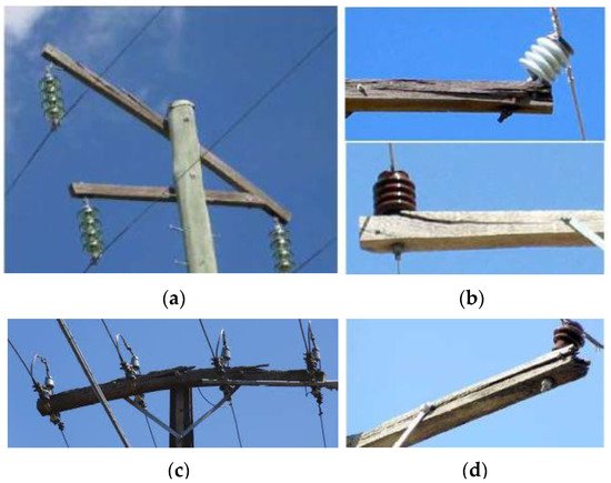
Figure 1 illustrates the deteriorated and failed timber crossarms subjected to the aforementioned causes. Flexure-induced splitting was observed in the majority of the crossarms. It is evident that most of the crossarms have failed or initiated the failure close to the location of end bots, which are supporting the insulators. Additionally, some failures can be observed at the vicinity of king bolt located at the centre of a crossarm, which is connecting the crossarm to the pole. The primary reason for this is the retention of moisture in bolt holes and the reduction in effective cross-sectional area of the crossarm due to the presence of the opening for the bolt to run through.
Figure 1. Deteriorated and failed timber crossarms due to decay and aeolian vibrations; (a) failed crossarm losing an insulator; (b) splitting at the end bolt locations; (c) badly split crossarm along the length; (d) losing sound wood at the end of the crossarm.
Except for the decay in crossarms, loosely connected king bolts and end bolts lead to enlargement of the bolt holes due to aeolian vibration. Alternating lift and drag forces induced by wind generate vibrations of overhead cables and these subsequently affect the crossarm connections. Improper bolted connections of the crossarms have a substantial effect of these vibrations initiating bolt hole enlargement. Continuation of the vibrations results in rapid progression of the bolt hole enlargement, which supports the retention of moisture and, thus, accelerated decay rates. Further, additional structural connections to crossarms exceeding the design specifications can be commonly observed in power distribution networks. Excessive load resulting from additional connections exceeding the design load can increase the probability of sudden crossarm failure without prior indications. The effects of these causes on timber crossarms are amplified, as wood is a natural material consisting of imperfections such as knots, splits, and slope of grain.
An accurate estimation of the remaining service life of crossarms is crucial for timely replacements that can avoid failures. Therefore, different condition assessment techniques are implemented in the field, considering the aspects of simplicity (ease of operation), accuracy, reliability, and safety of the operator. The conventional crossarm inspection techniques include visual inspection and sounding. However, given the subjective nature of these assessment techniques, more attention is paid towards the advancements in non-destructive testing (NDT) methods, which can eliminate the subjectivity and provide accurate results [
9]. More focus on NDT techniques for timber structures are on stress wave propagation, ultrasonic pulse velocity, vibration-based techniques, and tomography techniques (e.g., [
10,
11,
12]). The stress wave propagation technique is based on generation and propagation of either a longitudinal or transverse stress wave within the structure. Reflection patterns of the wave behaviour can be analysed to identify potential defects [
13]. In the ultrasonic pulse velocity technique, the time-of-flight method is utilised to determine the wave propagating speed, and this speed is generally used to comment on the condition of the tested structure [
14]. Vibration measurements are obtained in vibration-based techniques to correlate the strength with derived vibration properties and then to access the structural integrity. Tomography techniques provide local condition assessment by scanning the structure at selected locations and by evaluating the density [
15]. In addition to NDT techniques, flexural behaviour of crossarms is also investigated via laboratory experiments to understand the performance of intact and deteriorated crossarms belonging to different species.
2. Decay of Timber Crossarms and Decay Identification
The decay is caused by fungal attack, and different timber species possess different inherent resistance levels for decay. In Australia, three types of fungus are identified, namely, brown rot, white rot, and soft rot. This categorisation is based on the chemical components of wood which they are attacking and the colour of infested wood [
17]. Wang et al. [
18] investigated the decay rates and identified that there is a difference in the decay rates even across a cross-section of a timber log. For untreated timber, sapwood indicated the highest decay rate in comparison with inner and outer heartwood. When sapwood was treated, it had a lower decay rate compared to heartwood. Therefore, the treatment process has substantial effects on the decay of crossarms. For the preservative treatment of timber, copper chromium arsenate (CCA), alkali copper quaternary (ACQ), and creosote can be used.
Retention of moisture on the bolt holes and the top surface of crossarms is identified as a major cause for increased decay rates. Khalid et al. [
19] explored the capability of decay detection in wooden crossarms by implementing the microwave reflection method. The crossarms were categorised into three distinct groups, such as severe decay, incipient decay, and sound wood. This categorisation was based on the amount of moisture that can be absorbed by wood and the density of wood based on different decay stages. Results indicated that the proposed method was able to measure the defective area up to 2 cm from the surface of wood. Further, Khalid et al. [
20] investigated the applicability of ultrasonic techniques to find a suitable method of measurement to determine the decay under the connecting metal blocks. For this ultrasonic pulse velocity method, the time-of-flight method was employed in the analysis to assess the condition of the crossarm. With the increase of the degree of defect, ultrasonic wave traveling times were observed to be increasing. Thus, the ultrasonic wave transit time was an indirect measurement providing the presence and degree of decay in wooden crossarms.
The remaining strength of a crossarm is directly related to the degree of surface decay. Ho et al. [
21] developed a statistical model which correlates the amount of surface deterioration to the remaining strength of rectangular Douglas fir crossarms. An image processing technique was employed to accurately quantify the amount of deterioration. The image processing technique could overcome the subjectivity involved in the conventional visual inspection technique. It was identified that the decay in a high-stress zone has a prominent influence on the loss of strength compared to the decay in a low-stress zone. The high-stress zone of a crossarm was chosen as 1 ft from each side of the pole support. In addition, it was noticed that the presence of natural imperfections such as knots and slope of grain affected the remaining strength of a crossarm.
3. Flexural Strength of In-Service Crossarms
Timber, as a natural material, inherits imperfections and growth defects. Some of these are the slope of grain and presence of knots, splits, and checks. Standards specify the requirements and guidelines to be considered when selecting suitable timber for crossarms (e.g., [
22,
23,
24]). These standards specify limits for the allowable knot size, slope of grain, checking, splitting, and presence of other defects. Researchers have paid attention to investigating the flexural strength of crossarms by conducting bending tests. Different species of wood, different crossarm geometries, effect of strengthening techniques, and effect of decay and knots are explored in terms of the bending capacity. Three-point and four-point bending tests are conducted for full-scale crossarms, or sometimes only for the critical regions of crossarms, to determine the bending strength parameters, such as modulus of rupture (MOR) and modulus of elasticity (MOE). A summary of the studies on flexural strength assessment of timber crossarms is presented in
Table 2.
Table 2. Studies that examined the flexural strength of timber crossarms.
Some of the previous studies have neglected the way in which the crossarm is connected to the utility pole and the connection of the crossarm to the overhead cables.
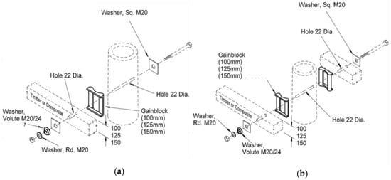
Figure 4 illustrates a single crossarm and double crossarm assembly presented in [
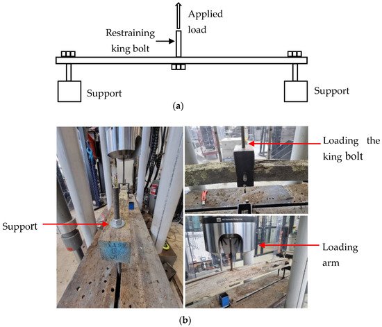
31]. A 20 mm bolt, typically called the king bolt, connects the crossarm to the utility pole and a gain block is placed in between to have a strong connection. This connection detail needs to be replicated in the bending test setup. Schematic representation of the three-point bending setup is illustrated in
Figure 5a and the actual test setup is shown in
Figure 5b. Vertical supports are provided at around 100 mm from the two ends of the crossarm specimens. Authors carried out three-point bending tests for 110 decommissioned timber crossarms collected around various parts of Victoria, Australia. These specimens were from three different power distribution networks. A king bolt was placed at the middle and a displacement-controlled load was applied, according to the Australian standard specifications. Breadth of the rectangular specimens ranged from 85 to 125 mm and the height range was 70 to 155 mm. Test spans varied from 1.7 to 2.5 m, depending on the crossarm geometry, and the bolt sizes were 20, 25, and 30 mm. Tested specimens were from different species belonging to both softwood and hardwood.
Figure 4. Predrilled crossarm assembly: (
a) single crossarm; (
b) double crossarm [
31].
Figure 5. Three-point bending test setup: (a) schematic representation; (b) actual test setup.
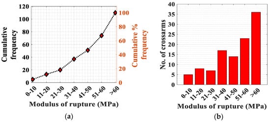
Figure 6a illustrates the cumulative frequency distribution of the MOR for the tested crossarms. The MOR indicates the failure flexural strength of tested specimens. The failure load was recorded from the experiments for each specimen to calculate the failure moment. The section moduli of crossarms were calculated using the measured breadth and height. Then, the simple bending theory was used in calculating the MOR with the use of failure moment and the section modulus. From the visual examination before the testing, crossarms were observed having light, moderate, and severe degradations. Therefore, a significant variation of the MOR can be observed, as evidenced in Figure 6a. When a crossarm is subjected to deterioration, the material properties, such as density and MOE, can degrade, leading to reduced fibre strength. In addition, deterioration can result in loss of sound wood, reducing the effective section modulus. This depletion is substantial if the loss of sound wood is from the exterior of the crossarm rather than from the interior, since loss of material at the perimeter of the cross-section will have the highest reduction in the section modulus. The highest and lowest MOR were 123 and 2.1 MPa, respectively. The average MOR for the tested 110 crossarms was 52.5 MPa. Except for the degree of deterioration of a crossarm, the species of wood belonging to softwood or hardwood and its strength grading directly affected the bending strength indicators. Bending tests were carried out using condemned crossarms from service and finding a relatively large number of crossarms from the same timber species is practically challenging. Thus, the influence of timber species on the calculated MOR cannot be avoided when interpreting the results. Figure 6a indicates that ~50% of the tested poles had MOR values lower than 50 MPa. Figure 6b denotes that about 35 crossarms showed MOR above 60 MPa, which corresponds to light deterioration. These crossarms with a MOR above 60 MPa can still be used in the field, although they have been condemned. This reflects the inaccuracy of the current practices in the condition assessment: specifically, misdiagnosing the defects. Critical region of the crossarms was found to be around the king bolt where the highest stresses are present. The calculated MOR values for the tested specimens can be used to benchmark the health ratings of inspectors to improve the visual examination rating system. Visual examinations were carried out by inspectors before condemning the tested crossarms. Thus, each tested crossarm possesses visual examination results and health ratings based on the examination. Once bending tests are carried out, flexural strength of each crossarm is determined, and subsequently, the health rating of inspectors can be benchmarked. If a particular crossarm with a good health rating from visual inspection is providing a lower MOR from bending tests, it indicates that the visual examination has overlooked defects. When it is the other way around, it indicates that the visual examination has misdiagnosed defects.
Figure 6. (a) Variation of the modulus of rupture—110 specimens; (b) groupings of the modulus of rupture.
This entry is adapted from the peer-reviewed paper 10.3390/infrastructures7070094