 +1 credit
| Version | Summary | Created by | Modification | Content Size | Created at | Operation |
|---|---|---|---|---|---|---|
| 1 | Maher A.R. Sadiq Al-Baghdadi | -- | 2161 | 2022-07-30 19:53:47 | | | |
| 2 | Maher A.R. Sadiq Al-Baghdadi | Meta information modification | 2161 | 2022-07-31 01:01:35 | | | | |
| 3 | Catherine Yang | -14 word(s) | 2147 | 2022-08-01 03:38:50 | | |
Video Upload Options
The mechanical durability of PEM fuel cells is a significant barrier to commercializing these systems for stationary and transportation power applications. The performance of a PEM fuel cell or stack is affected pointedly by the degradation of its components materials. Performance degradation is unavoidable, but the degradation rate can be minimized by comprehensively understanding degradation and failure mechanisms. Furthermore, the degradation processes of the different components are often interconnected in fuel cells. Therefore, the degradation phenomena of each fuel cell component must be separated, analyzed, and systematically understood to develop novel component materials and build novel cells/stacks that mitigate insufficient fuel cell mechanical durability.
1. Introduction
Proton exchange membrane fuel cells, also known as polymer electrolyte membrane (PEM) fuel cells, are electrochemical energy conversion technology that directly converts the chemical energy of hydrogen fuels to electricity with high efficiency and no emissions. However, they have limited market penetration due to their high cost, which stems from the need to balance durability, performance, and materials [1].
PEM fuel cells are made from several layers of different materials. PEM fuel cells contain many components, including membranes, catalysts layers (CL), gas diffusion layers (GDL), bipolar plates, and gaskets. The membrane electrode assembly (MEA) consists of a polymer electrolyte membrane, both faces providing a catalyst layer and gas distribution layers (anode and cathode). Each of these components can degrade or fail to function, thus causing the fuel cell system to degrade or fail (Figure 1) [2].
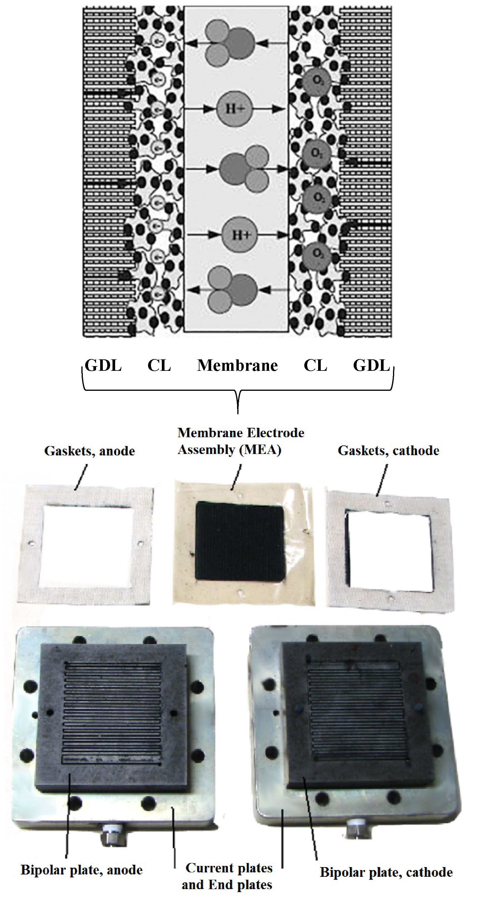
Figure 1. PEM Fuel cell components.
1.1. Membrane
The polymer electrolyte membrane or PEM (also called a proton exchange membrane) is a specially treated material that conducts only positively charged ions and blocks the electrons. The PEM is the key to fuel cell technology; it must allow only the necessary ions to pass between the anode and cathode. Other substances passing through the electrolyte would disrupt the chemical reaction. The membrane is very thin, sometimes under 20 microns for transportation applications. With respect to membrane durability, significant achievements have been made by stabilizing the ionomer to improve its chemical stability and by using reinforcement methods to enhance its mechanical stability. The answer lies in developing new ionomer materials and corresponding membranes that will possess higher thermal stability, better mechanical properties to combat gas crossover, and greater chemical stability against reactive radicals. It is also essential to develop new catalysts that produce less harmful species. The membrane's mechanical degradation is the main cause of early-stage failure in the PEM fuel cell lifetimes [3].
1.2. Catalyst Layers (CL)
A layer of catalyst is added on both sides of the membrane; the anode layer on one side and the cathode layer on the other. Conventional catalyst layers include nanometer-sized particles of platinum dispersed on a high-surface-area carbon support. This supported platinum catalyst is mixed with an ion-conducting polymer (ionomer) and sandwiched between the membrane and the GDLs. On the anode side, the platinum catalyst enables hydrogen molecules to be split into protons and electrons. On the cathode side, the platinum catalyst enables oxygen reduction by reacting with the protons generated by the anode, producing water. The ionomer mixed into the catalyst layers allows the protons to travel through these layers. Catalyst degradation during the long-term operation of PEM fuel cells under universal conditions is a complex process that includes many parallel mechanisms. Several factors, such as fuel cell operating conditions, preparation conditions, and catalyst type, can affect catalyst degradation. Catalyst support degradation has been identified as a crucial PEM fuel cell degradation mechanism, especially in automotive applications. The increased voltages, humidity, load cycling, and impurities can cause structural and chemical changes to the carbon support or cause operational changes such as local/gross fuel starvation, which accelerates carbon corrosion even further [4].
1.3. Gas diffusion layers (GDL)
The GDLs sit outside the catalyst layers and facilitate the transport of reactants into the catalyst layer and the removal of product water. Each GDL is typically composed of a sheet of carbon paper in which the carbon fibres are partially coated with polytetrafluoroethylene (PTFE). Gases diffuse rapidly through the pores in the GDL. The hydrophobic PTFE keeps these pores open, which prevents excessive water buildup. In many cases, the inner surface of the GDL is coated with a thin layer of high-surface-area carbon mixed with PTFE, called the microporous layer. The microporous layer can help adjust the balance between water retention (needed to maintain membrane conductivity) and water release (needed to keep the pores open so hydrogen and oxygen can diffuse into the electrodes). Typical GDL configurations consist of a macroporous layer and a microporous layer (MPL). The macroporous layer provides an electrical and thermal connection to the flow-field plates and facilitates species transport through macroscopic pores. The MPL controls the water fluxes near the catalyst layer and reduces the contact thermal and electrical resistances. The most critical degradation is related to changes in mass transport. Of these, the changes associated with liquid water, oxygen, and water vapour have the most significant impact on performance and durability. The most important degradation mechanisms include chemical and electrochemical hydrophobicity changes on the surfaces and porous layers [5].
1.4. Bipolar plates
Each individual MEA produces less than 1 V under typical operating conditions, but most applications require higher voltages. Therefore, multiple MEAs are usually connected in series by stacking them on top of each other to provide a usable output voltage. Each cell in the stack is sandwiched between two bipolar plates to separate it from neighbouring cells. These plates, which may be made of metal, carbon, or composites, provide electrical conduction between cells and physical strength to the stack. The surfaces of the plates typically contain a “flow field,” which is a set of channels machined or stamped into the plate to allow gases to flow over the MEA. Additional channels inside each plate may be used to circulate a liquid coolant. Bipolar plates, in two ways, can contribute to the limited lifetime of PEM fuel cell stacks: first is the physical decomposition of the materials or parts of the materials resulting in mechanical instability, leakage or decrease of electrical conductivity; second is the release of additives and materials to the fuel cell environment forcing degradation processes in further fuel cell parts such as gaskets, MEAs, and peripheral components. These phenomena are to be considered both for composite-based and metal-based bipolar plates. Using composites the fuel cell contamination due to filler or plastic impurities is more essential than the overall plate’s stability. The best strategy to avoid a breakdown or failure during fuel cell operation is the right choice of polymer. Criteria for the right choice are cost, processability, and, more importantly, corrosion stability. As the stability of commercially available plates is good, most applications demanding long-term operation, higher temperatures, and other complex environments rely on composite-based plate technologies. For metal bipolar plates, the stability of the bipolar plate, especially against corrosion, has to be brought more into focus. A suitable base material combined with a conductive and protective coating is the only way to extend the lifetime of the plates. Nevertheless, metallic bipolar plates are the preferred choice for all applications attending to small volume and weight and without high lifetime demand [6].
1.5. Gaskets, Current plates, and end plates
Each MEA in a fuel cell stack is sandwiched between two bipolar plates, but gaskets must be added around the edges of the MEA to make a gas-tight seal. These gaskets are usually made of a rubbery polymer. The properties of the gaskets have a significant influence on PEM fuel cell performance, especially durability. Satisfactory, economical sealing within a multi-material stack is an essential factor in the commercialization of PEM fuel cells. The primary role of the endplate is to ensure uniform pressure distribution in each active area and thereby reduce contact resistances among all the components inside the fuel cell stack, such as bipolar plates, gas diffusion layers, and catalyst layers. Current plates function as an external electric circuit, exporting the electric current from the fuel cell. The current plate materials may influence fuel cell performance [7].
2. Failure modes
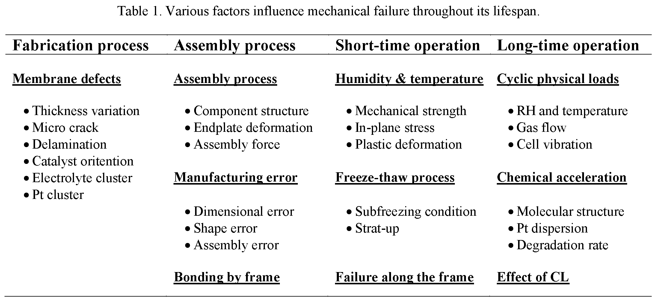
Mechanical failure in PEM fuel cells is the most harmful to the cell, which causes its short life. The mechanical failure results from the local stress concentration and mechanical stress variation on the constrained membrane under the alternating swelling and shrinking in response to the changes in water content and temperature. As a result, material fatigue, creep, and the generation of wrinkles, delamination, pinholes, tears or cracks are initiated and propagated on the surface or across the bulk of the membrane, which inherent defects would exacerbate the membrane occurring during the fabrication process or the improper assembly of fuel cell stacks. Many external and internal factors can cause membrane mechanical failure, including the fabrication of the membrane, the assembly of the fuel cell, the quality of the assembled components, and the conditions of operation. Table 1 summarizes the main factors influencing mechanical failure [8].
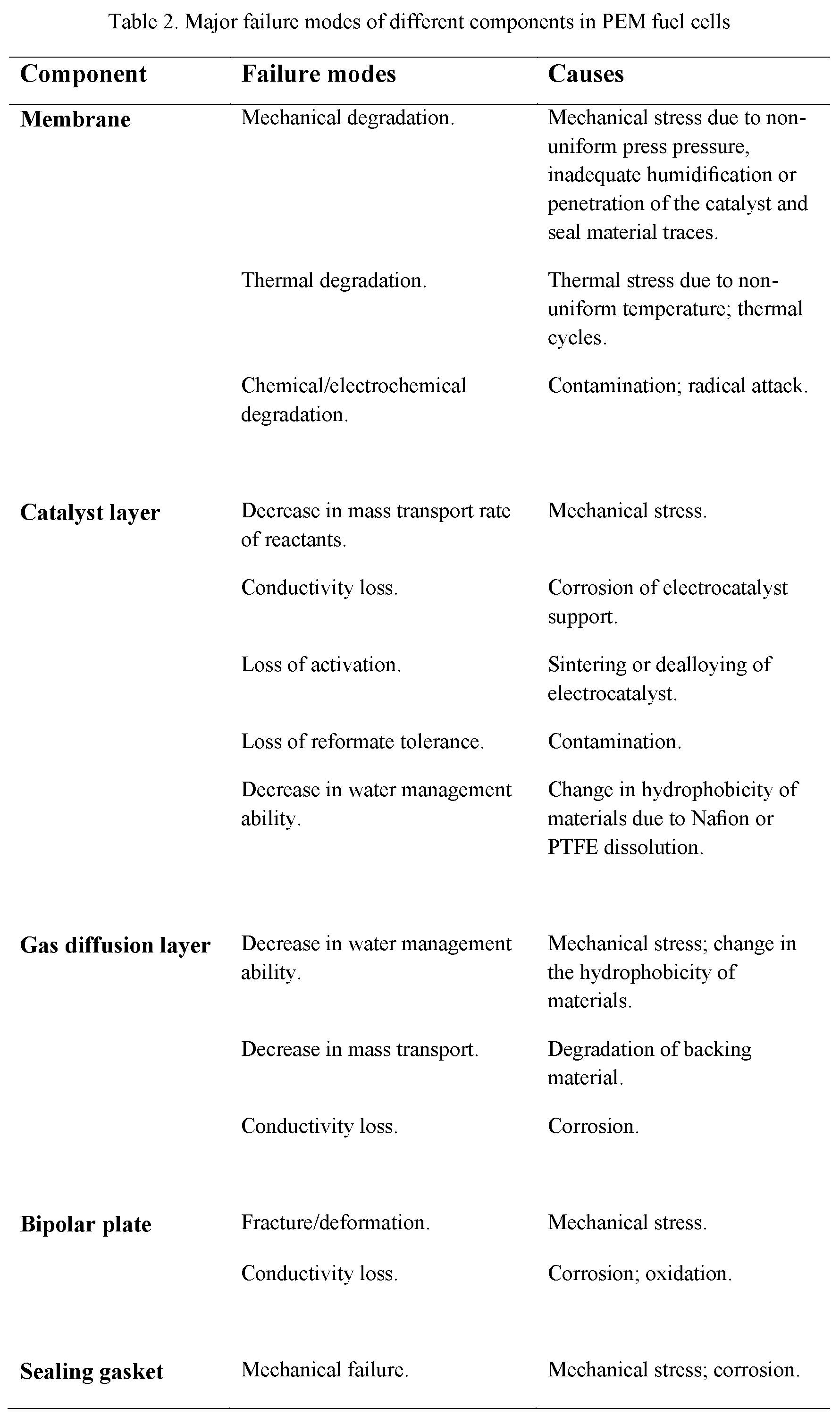
The major failure modes for PEM fuel cell components, including the membrane, catalyst layer, gas diffusion layer, bipolar plate, and sealing material (gasket), are listed in detail in Table 2 [9].
3. Mechanical stress due to non-uniform temperature, humidity, and assembly press pressure
The fuel cell stack is sized to generate the designed power output. PEM fuel cells show some efficiency and power density losses with the scale up when the number of cells and their areas increases in a stack. As fuel cell manufacturing scales up, the relationship between fuel cell performance and design, manufacturing, and assembly processes must be well understood. The PEM fuel cell stack is a sandwich-like structure composed of many layers, materials and interfaces. Therefore, the pressure distribution in the PEM fuel cell stack is affected by the component material properties, geometrical parameters and the clamping method. Assembly pressure plays a significant role in determining fuel cell performance. During the assembly of a PEM fuel cell stack, GDL, bipolar plate, and membrane are clamped together using mechanical devices. A proper level of clamping pressure is needed to provide adequate gas sealing and reduce contact resistances at component interfaces. However, too high a pressure may over-compress the membrane and GDL, crushing their porous structures and cracking the bipolar plate. In addition, the electrical contact resistance, which constitutes a significant part of the ohmic resistance in a cell, especially when stainless steel, titanium or moulded graphite is chosen as the bipolar plate material, can be significantly altered by clamping pressure and operating conditions. Assembly pressure makes the part of GDL under the land area be compressed, and the part under the channel area be protruded into the channel cavity. This inhomogeneous compression causes unevenness of the material properties of GDL. The inhomogeneous deformation of GDL and significant change of material properties influence fuel cell performance and durability dramatically [10].
PEM fuel cell stack assembly process, including clamping pressure, material properties of each component, design (component thickness and cell active area), and the number of cells in the stack, are essential factors influencing the performance and durability of the PEM fuel cell stack. Furthermore, the membrane absorbs water and swells when temperature and relative humidity increase during operation. Since the relative position between the top and bottom end plates is fixed, the polymer membrane is spatially confined. Thus the GDL will be further compressed under the land, and the intrusion into the channel will become more significant. Assembly pressure, contact resistance, membrane swelling and operating conditions, etc., combine to yield an optimum assembly pressure.
Variations in temperature and humidity during operation cause stresses and strains (mechanical loading) in the membrane as well as in all components and are considered to be the mechanical failure driving force in fuel cell applications. Investigating the mechanical response of the PEM fuel cell stack during operation (subjected to changes in humidity and temperature) requires studying and modelling the stress-strain behaviour of all fuel cell stack components in the operation phase [11].
The use of the CFD technology allows the study of the physical phenomenon within a fuel cell stack, such as heat and energy transport, as well as the pressure distribution inside all components of the stack without the need to build a structure, eliminating the manufacture and machining costs. The 3D CFD model enables the prediction of the distribution and visualization of various parameters influencing the stack behaviour. Figure 2 shows specific results from the study of the pressure effects by combining the mechanical and electrochemical phenomena in the PEM fuel cell stack (assembly and operation effects). For detailed computational details, see reference [12].
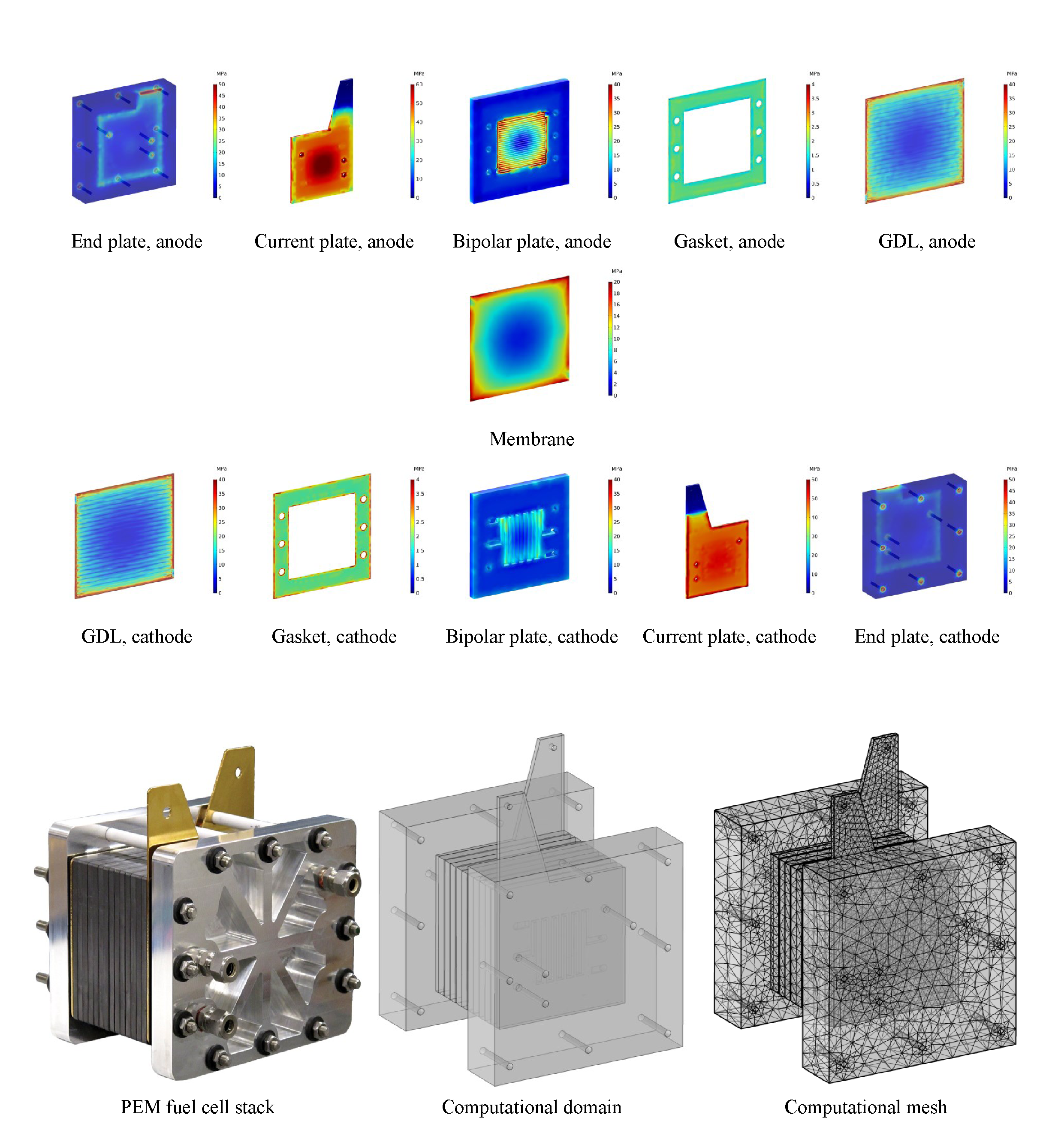
Figure 2. von Mises stress distribution in the PEM fuel cell stack components during operation, Tcell=80 C, Pc = Pa=3 atm [12].
4. Conclusions
The work aims to establish a backbone understanding of the phenomenological processes that occur within the PEM fuel cells, how they interact, how they are influenced through elements of design, manufacturing and operation, and ultimately how they result in performance degradation and cell mechanical failure.
References
- Maher A.R. Sadiq Al-Baghdadi. CFD Models for Analysis and Design of PEM Fuel Cells. NOVA SCIENCE PUBLISHERS, INC, 400 Oser Avenue, Suite 1600, Hauppauge, NY 11788-3619 USA. 2008, (202 pages). ISBN-13: 9781604569971.
- Maher A.R. Sadiq Al-Baghdadi. A CFD study of hygro-thermal stresses distribution in PEM fuel cell during regular cell operation. Renewable Energy Journal 2009; 34(3) pp.674-682.
- Maher A.R. Sadiq Al-Baghdadi. Influence of the design parameters in a proton exchange membrane (PEM) fuel cell on the mechanical behaviour of the polymer membrane. Energy & Fuels. An American Chemical Society Journal 2007; 21(4) pp.2258-2267.
- Maher A.R. Sadiq Al-Baghdadi. Influence of the operating parameters in a proton exchange membrane (PEM) fuel cell on the mechanical behavior of the polymer membrane. Fuel Cell 2008; 8(1) pp.34-39.
- Maher A.R. Sadiq Al-Baghdadi. Effect of PEM fuel cell operation on gas diffusion layers and membrane stresses. International Journal of Fluid Mechanics Research 2008; 35(3) pp.219-234.
- Maher A.R. Sadiq Al-Baghdadi. Design Optimization of PEM Fuel Cells to Minimize the Maximum Thermal Stress. Chapter one in "Thermal Stresses: Design, Behavior and Applications" (Reference Book), NOVA SCIENCE PUBLISHERS, INC, 400 Oser Avenue, Suite 1600, Hauppauge, NY 11788-3619 USA. 2016, pp. 1-60. ISBN-13: 9781634853736.
- Maher A.R. Sadiq Al-Baghdadi. Prediction of hygro-thermal stresses distribution in proton exchange membranes using three-dimensional multi-phase computational fluid dynamics model. Proceedings of the I MECH ENG. Journal of Power and Energy 2007; 221 (7) pp. 941-953.
- Maher A.R. Sadiq Al-Baghdadi. CFD Analysis of the Clamping Pressure Distribution in Running PEM Fuel Cell. Chapter three in "PEM Fuel Cells: Theory, Performance and Applications" (Reference Book), NOVA SCIENCE PUBLISHERS, INC, 400 Oser Avenue, Suite 1600, Hauppauge, NY 11788-3619 USA. 2015, pp. 111-166. ISBN-13: 9781634822275.
- Maher A.R. Sadiq Al-Baghdadi. Computational Modeling Aspects of Polymer Electrolyte Fuel Cell Durability. Chapter one in "Computational Fluid Dynamics: Theory, Analysis and Applications" (Reference Book), NOVA SCIENCE PUBLISHERS, INC, 400 Oser Avenue, Suite 1600, Hauppauge, NY 11788-3619 USA. 2011, pp. 1-40. ISBN-13: 9781612092768.
- Maher A.R. Sadiq Al-Baghdadi. Effect of operating parameters on the hygro-thermal stresses in proton exchange membranes of fuel cells. International Journal of Hydrogen Energy 2007; 32(17) pp.4510-4522.
- Maher A.R. Sadiq Al-Baghdadi. Prediction of deformation and hygro-thermal stresses distribution in ambient air-breathing PEM fuel cells using three-dimensional CFD model. Recent Patents on Mechanical Engineering 2009; 2(1) pp.26-39.
- Maher A.R. Sadiq Al-Baghdadi. PEM FUEL CELLS - From Fundamentals to Research Studies. International Energy and Environment Foundation. 2020, (478 pages). ISBN-13: 9798634858883.

