Your browser does not fully support modern features. Please upgrade for a smoother experience.
Submitted Successfully!
 +1 credit
Thank you for your contribution! You can also upload a video entry or images related to this topic.
For video creation, please contact our Academic Video Service.
| Version | Summary | Created by | Modification | Content Size | Created at | Operation |
|---|---|---|---|---|---|---|
| 1 | Massimo Ruo Roch | -- | 2674 | 2022-07-19 11:04:46 | | | |
| 2 | Rita Xu | -22 word(s) | 2652 | 2022-07-20 04:44:44 | | | | |
| 3 | Rita Xu | + 8 word(s) | 2660 | 2022-07-21 08:36:30 | | | | |
| 4 | Rita Xu | + 1 word(s) | 2661 | 2022-07-22 07:41:33 | | |
Video Upload Options
We provide professional Academic Video Service to translate complex research into visually appealing presentations. Would you like to try it?
Cite
If you have any further questions, please contact Encyclopedia Editorial Office.
Roch, M.R.; Martina, M. Virtual Lab. Encyclopedia. Available online: https://encyclopedia.pub/entry/25265 (accessed on 25 July 2026).
Roch MR, Martina M. Virtual Lab. Encyclopedia. Available at: https://encyclopedia.pub/entry/25265. Accessed July 25, 2026.
Roch, Massimo Ruo, Maurizio Martina. "Virtual Lab" Encyclopedia, https://encyclopedia.pub/entry/25265 (accessed July 25, 2026).
Roch, M.R., & Martina, M. (2022, July 19). Virtual Lab. In Encyclopedia. https://encyclopedia.pub/entry/25265
Roch, Massimo Ruo and Maurizio Martina. "Virtual Lab." Encyclopedia. Web. 19 July, 2022.
Copy Citation
VirtLAB is a Low-Cost Platform for Electronics Lab Experiments. The recent SARS-CoV2 pandemic has put a great challenge on university courses. Electronics teaching requires real laboratory experiences for students, which cannot be realized if access to physical infrastructures is prohibited. A possible solution would be to distribute to students, at home, electronics equipment suitable for laboratory experiments, but no reasonable product is currently available off-the-shelf.
electronics lab
virtual lab
electronics teaching
FPGA
Microcontroller
1. Introduction
Starting from the spring of 2020, the SARS-CoV2 pandemic hit China, Italy, and the rest of the world. Lockdown countermeasures were mandatory in order to mitigate virus spread among the population. This means that teaching ’in presence’ was stopped, too, in schools of every rank, from primary up to universities [1].
Current Internet capabilities allow researchers to overcome difficulties related to lectures, as videoconferencing is a well-established technique [2], even if there are some challenges that arise when the number of attendants goes beyond some hundreds if direct interactivity is desired (this concerns real-time lessons, and not just playing recorded videos) [3]. Nowadays, host virtualization and private or public clouds are already used inside universities, allowing researchers to deploy into the campus remote access to computing platforms [4], even at a supranational level [5].
Moreover, web applications allowing researchers to exploit interactivity in simulated environments, such as Moodle [6], are of widespread usage, and can be used to introduce exercises and simulated laboratory experiments, in which, students can interact with virtual objects, changing their parameters and simulating the behaviour of the so-modified experiments.
Electronics engineering courses are natural candidates for these kinds of web-based tools. As an example, in analog and digital electronics courses, students can design circuits, either via schematic capture or Hardware Description Languages (VHDL, Verilog, SystemC). Later, they can perform analog, digital, or mixed-signal simulations, utilizing web interfaces toward standard simulation tools (Spice, Modelsim) [7][8].
What is missing in this approach is the contact with real-world objects, which, according to researchers, is fundamental for the acquirement of specific engineering skills. In fact, developing design capabilities requires acquiring the following abilities:
- (a)
-
Design space exploration;
- (b)
-
Simulation of the designed system;
- (c)
-
Verification of compliance to a previously defined high-level reference model through every refinement step;
- (d)
-
Hardware verification, with limited debugging capabilities;
- (e)
-
Characterization of the hardware system.
Points (a) through (c) can be easily accomplished with the web-based methodologies described above. However, the last two items are, nowadays, not affordable at all.
First of all, it must be emphasized that simulation cannot fully substitute measurements performed on the real circuit. In fact, the major drawback of simulation performed inside courses is the lack of coverage of the tests, mainly due to student inexperience and time shortages. Therefore, hardware verification is necessary.
Moreover, the ability to diagnose real circuit faults is a typical high-value engineering skill that must be pursued. In addition, it requires skills in both real measurement instrument usage and the personal development of fault search methodologies specifically targeted toward digital or analog circuits.
Lastly, real signals are usually very different from simulated ones, sometimes in surprising ways for a student, and it is important to be able to visualize them in a realistic manner, as sampled by a real measurement instrument, including noise and other artifacts.
2. System Architecture
The basic idea is to develop a hardware device with two sections. The first one, called the "master area", is designed to resemble a typical lab desk, integrating the functionalities of a digital storage oscilloscope (DSO), a standard multimeter, and a programmable analog signal generator. Moreover, in this section, the teacher can load special purpose devices, e.g., test beds for the lab experience carried out by students. The second section ("user area") must instead be the equivalent of a prototype board, on which, students can carry out the experiment itself.
The board must be easily connected to a computing device (PC, Raspberry, etc.), where high-cost computational tasks can be performed. These tasks are, as an example, signal analysis algorithms (FFT, noise filtering, digital protocol analysis), data presentation to the user, and virtual instrument controls.
The integration of custom hardware and software running on the computing device is the key to minimizing the cost of the overall system. In fact, repetitive costs (hardware) are minimized at the expense of designing PC software, but the latter can be developed through an Open Source model. This choice introduces a further possibility, i.e., to involve computer science students in the development of this software, too. This fulfills another teaching activity, well-integrated inside an IT degree, even if not strictly required by initial specifications.
In this architecture, students can access the experimental board either directly or through the Internet, where a Raspberry PI or a laboratory server exposes the user interface.
The overall architecture is depicted in Figure 1.
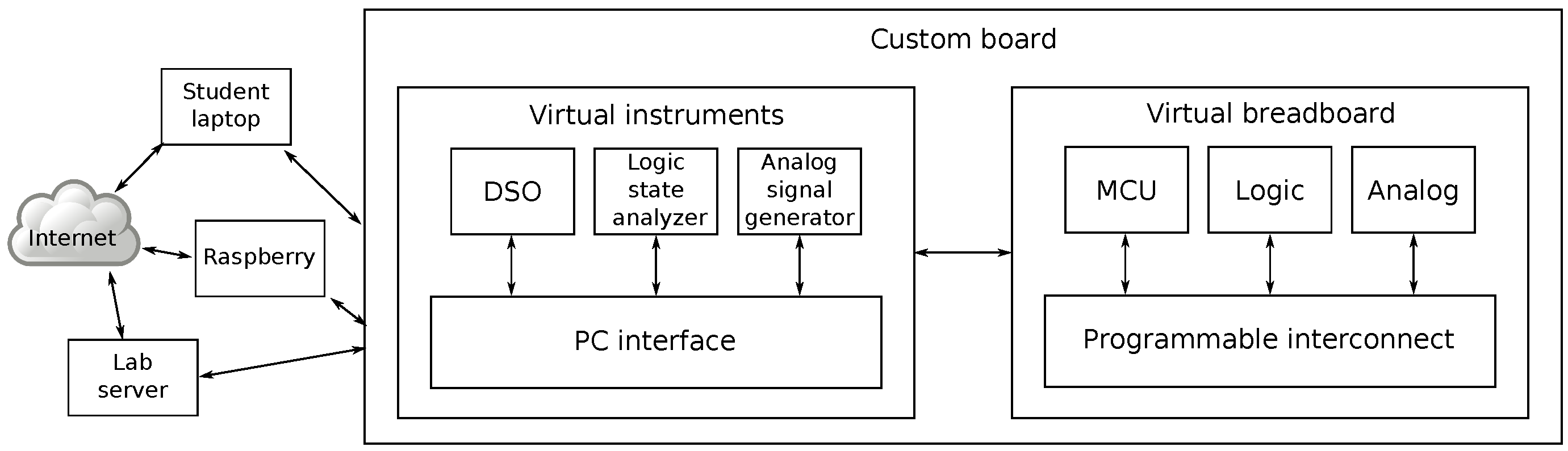
Figure 1. Basic architecture of the system.
3. Design of a First System
To assess the feasibility of the proposed approach, a first system was designed, specifically aimed toward electronics engineering courses in a master’s degree. Target courses are related to embedded systems design, low-power digital electronics, programmable logic, and bio-medical electronics systems. Skills acquired by students are mainly in the field of HDL design methodology, MCU hardware/software integration, embedded systems firmware development, analog and digital data acquisition and processing techniques, and hardware/software low power design.
The design started collecting a set of all of the lab experiences currently carried out in the above courses using off-the-shelf instruments and platforms. From these, a common base of required hardware facilities was extracted, resulting in an inventory of mandatory features. This way, the board guarantees that it will be capable of implementing all of the required lab experiments.
An extract of the main experiments is as follows:
-
Generation of digital waveforms with I/O ports of a microcontroller. Timing comparisons for polling, interruption, and hardware timer-assisted generation.
-
Audio signal acquisition from digital microphones. Signal reconstruction with MCU and FPGA. Sound event detection. Sound source direction detection through stereo microphones.
-
Acquisition of real time data from three-axis accelerometers. Position calculation via MCU and FPGA. Graphics representation in an FPGA-based frame buffer.
-
Implementation of serial communication peripherals IP and testing on FPGA (I2C, RS232).
-
Implementation of parallel bus handshake protocols master and slave (synchronous, semi-synchronous, asynchronous).
-
Implementation of hardware computing accelerators (FIR, IIR, FFT, AI). Power consumption optimization techniques.
Thereafter, features not substantially increasing the total cost of the board are introduced in order to maximize the flexibility to implement new experiences. As an example, if the maximum number of digital I/O pins needed to implement existing labs was 13, and supposing that I/O ports are commonly available with 8 bit parallelism, it will be straightforward to have 16 I/O pins, with a negligible cost increment.
A high-level block diagram of the board is visible in Figure 2.
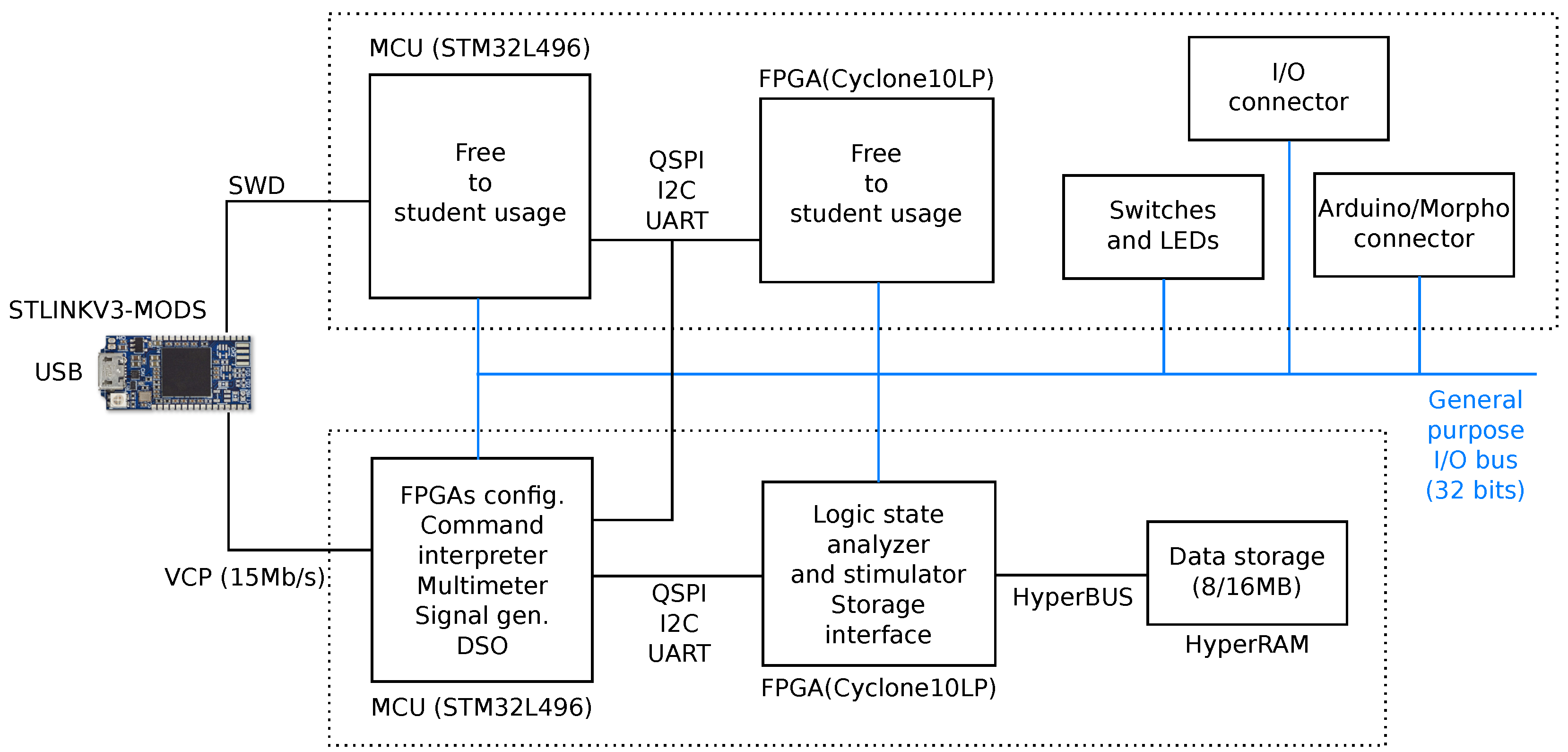
Figure 2. Block diagram of the designed board.
Three main blocks are visible: the user area (upper half), the master area (lower half), and the USB interface (STLinkV3MODS, at extreme left). The master and user sections are linked by a 32 bit general purpose bus, which is freely usable by experiments. The same bus is exposed through I/O pins, too.
Not visible in the diagram is the power supply section, which is needed to feed the right voltages and currents to on-board devices.
3.1. Master Section Specifications
The design of this area must be carried out by exploiting a trade-off between costs and performances. The first step is to then define virtual instrument specifications, both in terms of the type and the performance.
It is clear that, given a target board cost of less than USD 100, it is impossible to use sophisticated analog circuits, and mixed-signal MCU capabilities must be exploited as much as possible. As a consequence, specifications must be compatible with standard low-cost commercial hardware availability. The design process will then use the identified requirements as hints, and not as mandatory specifications.
3.1.1. Digital Storage Oscilloscope
The DSO implemented will have limitations due to low-cost analog front-end performances (low precision, low sampling frequencies, etc.). However, this limitation can be converted to an advantage. In fact, having limited capabilities can allow the student to easily experience side-effects derived from system limitations. As an example, the injected switching power supply noise on DSO analog input channels can demonstrate the importance of CMRR at high frequencies, or the limited sampling rate can be used to directly show aliasing effects when the Nyquist criteria are violated.
In addition, a reduced instrument bandwidth is not a real problem for university courses. Typical laboratory experiences with analog signals are performed with frequencies from DC of up to 100 kHz. In addition, digital signals commonly used on prototype boards, too, have a bandwidth in the order of 100 kHz. The I2C standard, RS232, and SPI are typically used in teaching labs at those frequencies.
Then, it was considered reasonable to have the analog section have a bandwidth of less than 1 MHz.
Regarding input dynamics, as the input signals are mainly derived from the board itself, having a very wide range of accepted input voltages was not needed, limiting them to the power supply range of the system itself.
To simulate the behavior of a real oscilloscope in an effective way, including probes, a compensated divider with an attenuation of 10 is needed, followed by a rail-to-rail I/O operational amplifier with a gain of 10. The degree of compensation must vary by the user in order to be able to show under- and over-compensation effects on input signal visualization.
Two analog voltage input channels are the acceptable minimum to at least be able to compute transfer functions and component trans-characteristics, and to perform similar experiments.
The developed system can be used in courses that talk about low-power firmware and hardware design, too. Then, it could be interesting to have the capability on-board to perform supply current measurements on user section devices. This is a feature not often found in commercial instruments due to the need to break power supply lines feeding the device that is being tested. However, as user devices and virtual instruments are hosted by the same board, it is feasible to put some current sensors on supply rails. Ideally, every supply rail feeding devices in the user section must be instrumented, allowing for the separation of the integrated circuits core supply current from the I/O one. Acquired currents must be converted to voltages and sent to auxiliary channels of the DSO. To be able to correlate voltage input channels to current ones, a common trigger mechanism and common timescales must be provided.
Standard DSO triggering schemes must be provided (Auto, Normal, Single, Stop) with freely configurable edge polarity, too. Any input channel can be selected as a trigger event source, and an external digital trigger input source must be available, too, to synchronize measurements to digital hardware or software events.
No visualization interface is needed, and just raw data must be stored. Then, they can be sent to a host PC for data processing and viewing.
3.1.2. Multimeter
A digital multimeter is a useful tool to perform accurate analog measurements on a prototype board. However, as a two-channel acquisition system is already present to implement the digital storage oscilloscope, it seems reasonable to use it directly as a multimeter. In fact, the higher precision required can easily be exchanged with the reduced bandwidth. In other words, a low resolution, moderate bandwidth, and noisy signals acquired by the DSO can be numerically processed through digital filters to improve the signal-to-noise ratio at the price of a low-pass filter. There is no need to perform this kind of processing task on-board, as it can be easily accomplished by the host interface. Moreover, the fact that there are two DSO voltage input signals means that differential measurements can be easily performed by just subtracting, sample-by-sample, the two input data streams. As a consequence, no further design was needed, despite the introduction of a virtual multimeter in the specifications.
3.1.3. Analog Signal Generator
A second mandatory virtual instrument is an analog signal generator. Typical waveforms available in commercial instruments include sine, triangular, and rectangular ones. To maximise flexibility and performances, an arbitrary waveform generator, generating outputs from stored digital samples, is needed. The samples can either be generated locally or transferred from the external controlling host.
One channel is mandatory, but two output channels are desirable, if possible, to allow for the generation of different waveforms injected in the same circuit (e.g., a high-frequency carrier, and a low-frequency modulation signal sent to a processing block, or quadrature sine waves used for QAM, PSK, etc.). If a second output channel is introduced, it must be able to be freely running, or synchronized to the first one, in order to maintain precise phase relationships.
From the point of view of generated frequencies, it seems reasonable to have bandwidths similar to DSO analog input channel ones, i.e., approximately 1 MHz.
3.1.4. Logic State Analyzer
A logic state analyzer is a commonly used analysis and debug tool used on digital circuits. Its applications range from the visualization of digital communication serial or parallel protocols to the study of the evolution of a finite state machine.
In a digital design course, this tool can simplify the detection of design flaws, such as the misbehaviour of control units or deviation from standards for communication protocols. Moreover, a decoding visualization interface can make it easier for the interpretation of a complex serial bus transaction, such as for I2C or SPI and their derivatives.
Nevertheless, it is not common to have logic state analyzers on laboratory benches due to the high cost of commercially available ones. This cost is mainly related to the need to have interfaces for different voltages, which vary according to the logic standard considered.
However, in this case, as the signal entering the instruments is typically generated by the board itself, there is no need to introduce expensive multichannel level translators, thus greatly simplifying the circuitry needed to implement a logic state analyzer.
From the point of view of required performances, it is reasonable to require sampling rates far higher than DSO ones in order to be able to use the logic state analyzer profitably in mixed-signal designs, where the digital data flow runs at word rates higher than analog sampling ones. Glitch detection must be implemented on each channel, too, which is a useful feature in static and dynamic hazards laboratory experiments.
A flexible triggering schema must be implemented in order to be able to check several inputs at once and to evaluate them against a digital pattern. If feasible, a triggering schema based on the detection of a specific sequence of digital patterns must be introduced too.
Raw acquired data must be stored locally, and later sent to the host PC for analysis and visualization.
Lastly, an eventual protocol-decoding capability, desirable from the point of view of data visualization, was delegated to the host controlling the board.
3.1.5. Digital Pattern Generator
This virtual instrument has a twofold application in laboratory experiments carried out on the designed board. First, it can be used by the teacher to generate test patterns, sent to the circuits designed by students, and implemented in the user section. As a second usage, it can be used by students to learn and check their ability to write adequate test patterns to verify a defined hardware behaviour, eventually computing the test coverage and reliability, too.
Given the unpredictability of use cases, it is preferable to have a simple table-driven pattern generator. In the case of complex protocol generation, the task of raw pattern generation is left to the host PC, which will send tabular data to the board.
The pattern generation speed must be comparable with the bandwidth of the logic state analyzer. In fact, it is not really useful to generate signals that cannot be acquired for the logic state analyzer, as, in this case, even the logic implemented in the user section to treat these signals would not be easily verifiable.
References
- Tropea, M.; Rango, F.D. COVID-19 in Italy: Current state, impact and ICT-based solutions. IET Smart Cities 2020, 2, 4–81.
- Kiss, G. Comparison of traditional and web-based education-case study “BigBlueButton”. In Proceedings of the 2012 International Symposium on Information Technologies in Medicine and Education, Hokodate, Hokkaido, Japan, 3–5 August 2012; pp. 224–227.
- Vasconcelos, P.R.M.; Freitas, G.A.d.; Marques, T.G. Virtualization technologies in web conferencing systems: A performance overview. In Proceedings of the 2016 11th International Conference for Internet Technology and Secured Transactions (ICITST), Barcelona, Spain, 5–7 December 2016; pp. 376–383.
- Roch, M.R.; Graziano, M. Teaching in the Cloud-Microelectronics Ubiquitous LAB (MULAB). In Proceedings of the 9th European Workshop on Microelectronics Education (EWME)”, Grenoble, France, 9–11 May 2012; pp. 131–135.
- Roch, M.R.; Demarchi, D.; Klossek, M.; Tzanova, S. MECA, the microelectronics cloud alliance. In Proceedings of the 2018 IEEE Global Engineering Education Conference (EDUCON), Tenerife, Spain, 17–20 April 2018; pp. 1419–1423.
- Available online: http://www.moodle.org (accessed on 25 March 2022).
- Magdin, M.; Cápay, M.; Halmeš, M. Implementation of LogicSim in LMS Moodle. In Proceedings of the 2012 IEEE 10th International Conference on Emerging eLearning Technologies and Applications (ICETA), Stara Lesna, Slovakia, 8–9 November 2012; pp. 57–59.
- Alajbeg, T.; Sokele, M. Implementation of Electronic Design Automation software tool in the learning process. In Proceedings of the 2019 42nd International Convention on Information and Communication Technology, Electronics and Microelectronics (MIPRO), Opatija, Croatia, 20–24 May 2019; pp. 532–536.
More
Information
Subjects:
Engineering, Electrical & Electronic
Contributors
MDPI registered users' name will be linked to their SciProfiles pages. To register with us, please refer to https://encyclopedia.pub/register
:
View Times:
910
Revisions:
4 times
(View History)
Update Date:
22 Jul 2022
Table of Contents


Notice
You are not a member of the advisory board for this topic. If you want to update advisory board member profile, please contact office@encyclopedia.pub.
OK
Confirm
Only members of the Encyclopedia advisory board for this topic are allowed to note entries. Would you like to become an advisory board member of the Encyclopedia?
Yes
No
${ textCharacter }/${ maxCharacter }
Submit
Cancel
Back
Comments
${ item }
|
${ item.createdUser.fullName }
${ item.createdAt }
${ item.vote }
${ item.reply }
Delete
${ reply.createdUser.fullName }
${ reply.createdAt }
${ reply.vote }
Delete
There is no reply to this comment~
${ item.replyTextCharacter }/${ item.replyMaxCharacter }
Submit
Cancel
More
No more~
There is no comment~
${ textCharacter }/${ maxCharacter }
Submit
Cancel
${ selectedItem.replyTextCharacter }/${ selectedItem.replyMaxCharacter }
Submit
Cancel
Confirm
Are you sure to Delete?
Yes
No