Your browser does not fully support modern features. Please upgrade for a smoother experience.
Submitted Successfully!
 +1 credit
Thank you for your contribution! You can also upload a video entry or images related to this topic.
For video creation, please contact our Academic Video Service.
| Version | Summary | Created by | Modification | Content Size | Created at | Operation |
|---|---|---|---|---|---|---|
| 1 | Kapil Gupta | -- | 2670 | 2022-07-03 07:10:28 | | | |
| 2 | Camila Xu | Meta information modification | 2670 | 2022-07-04 05:28:33 | | |
Video Upload Options
We provide professional Academic Video Service to translate complex research into visually appealing presentations. Would you like to try it?
Cite
If you have any further questions, please contact Encyclopedia Editorial Office.
Chaubey, S.K.; Gupta, K. The Advanced Micro-Drilling Process. Encyclopedia. Available online: https://encyclopedia.pub/entry/24767 (accessed on 26 July 2026).
Chaubey SK, Gupta K. The Advanced Micro-Drilling Process. Encyclopedia. Available at: https://encyclopedia.pub/entry/24767. Accessed July 26, 2026.
Chaubey, Sujeet Kumar, Kapil Gupta. "The Advanced Micro-Drilling Process" Encyclopedia, https://encyclopedia.pub/entry/24767 (accessed July 26, 2026).
Chaubey, S.K., & Gupta, K. (2022, July 03). The Advanced Micro-Drilling Process. In Encyclopedia. https://encyclopedia.pub/entry/24767
Chaubey, Sujeet Kumar and Kapil Gupta. "The Advanced Micro-Drilling Process." Encyclopedia. Web. 03 July, 2022.
Copy Citation
The increased demand for miniature components has drawn the attention of researchers, engineers, and industry users to manufacture precision micro and mesoholes on foils, sheets, and plates made from a variety of engineering materials. Due to the inherent limitations of conventional drilling processes, the modern or advanced drilling processes are being used to fabricate fine and deep precision holes in a wide range of materials. The spark erosion based drilling is one of them. A comprehensive detail on miniature hole fabrication by micro spark erosion machining (µ-SEM) and micro spark erosion drilling (µ-SED) is given.
material removal rate
microhole
erosion
machining
drilling
surface quality
spark
1. Introduction
Nowadays, the trend of miniaturized devices and products that are lightweight, smaller in volume, portable, cheaper, and stable in performance has become one of the fundamental necessities of several manufacturing industries, such as aerospace, automotive, medicine, biomedical, electronics, telecommunication, fluidics and consumer products [1][2][3]. Miniature deceives and products used in the abovementioned industries are printed circuit boards, pressure sensors, nozzles, accelerometers, microdies, molds, microreactors, microdroplet injectors, tooth grafting, medical appliances, fluid pumps, fuel filters, fuel injectors, optical scanners, and probes. Drilling is the most commonly used and basic machining operation in the manufacturing industries for making different types and sizes of holes on a variety of materials [4]. Drilled holes with a diameter of less than 1 mm (i.e., 1000 µm) are known as microholes [5]. Whereas, drilled holes with diameters ranging between 1–10 mm are stated as mesoholes. For the past two decades, the constraint of traditional drilling processes has become a major concern due to the requirement for higher drilling accuracy in modern industries [6]. The constraint of traditional processes for making high-quality small-sized holes or fine-holes has drawn the attention of researchers, engineers, and industrial users to explore alternative drilling processes to fabricate net-size or near-net-size microholes. The advanced micro-drilling process can produce microholes with diameters in a range of a few microns to hundreds of microns.
2. Selection of Materials for Drilling Deep Fine-Holes
The choice and range of materials for fine holes (i.e., meso and microholes) generally depend on types of application, material features (i.e., hardness and tenacity) of workpiece and drilling tools, drilling methods, and materials cost [7][8]. Commonly, miniature-sized holes are drilled on several metallic, non-metallic, and composite metals. Metallic materials are further divided into two categories, namely ferrous and nonferrous. Ferrous metals have higher strength than non-ferrous metals and are most suitable for various construction, structural, and industrial applications [9][10][11]. These materials comprise stainless steel, high-carbon steel, high-speed steel, and cast iron. Nonferrous materials, such as copper, aluminum, lead, zinc, brass, nickel, titanium, and their alloys, are more malleable, conductive, and easily handled in diverse manners. These materials are most preferable for applications where a humid environment would oxidize ferrous metals. These materials are also suitable for electrical components due to their non-magnetization characteristics. Non-metallic materials are different types of plastics, such as Delrin, polyvinyl chloride, acrylic, fiberglass, nylon, etc. These plastics are extensively used for lightweight and noiseless applications. A composite is a mixture of two materials having different characteristics (i.e., physical and chemical). Composite materials have lightweight qualities, high strength, stiffness, and they are resistant to electricity. Metal-matrix-composite, glass fiber reinforced-composite, fiberglass, carbon-fiber-reinforced-polymer, etc. are some commonly used composite materials that are widely used in aerospace, automotives, corrosive environments, maritime environments, and electrical parts and components.
3. Procedure of Experiments and Methods of Drilling Precision Deep Fine-Holes
The summary of the various methods for drilling miniature deep fine holes is presented in Table 1. These methods can be classified as (i) conventional drilling methods (CDMs); and (ii) advanced drilling methods (ADMs). Micro-lathe, micro-milling, and micro-drilling are the most commonly used conventional methods to produce miniature-sized holes in metals and non-metals with the help of the various drill bits. CDMs have some inherent limitations, such as tool wear, burr generations, geometrical inaccuracy, and low material removal rate. Therefore, advanced drilling methods are employed to overcome the restrictions of CDMs. ADMs can be classified as (i) mechanical erosion drilling (MED); (ii) thermoelectric erosion drilling; (iii) chemical form of drilling; and (iv) electrochemical drilling [12][13][14].
Table 1. Commonly used drilling methods for manufacturing miniature holes.
| Type | Methods | Nature of the Process | Manufacturing Process |
|---|---|---|---|
| Conventional drilling methods | Chip formation | Subtractive |
|
| Advanced drilling methods or Non-conventional drilling methods | Mechanical erosion drilling | Erosion |
|
| Thermoelectric erosion drilling | Controlled spark erosion |
|
|
| Thermoelectric vaporization |
|
||
| Chemical drilling | Chemical ablation |
|
|
| Electrochemical drilling | Ion displacement |
|
Mechanical erosion-based drillings are abrasive water jet drilling (AWJD) and ultrasonic drilling (USD). In these processes, materials are removed by the mechanical erosion of work material by high-pressure slurry (abrasive particles mixed with water). AWJD can produce miniature-sized holes on metallic and non-metallic materials. USD is used for machining miniature-sized holes on conductive and non-conductive materials having a hardness of more than 40 HRC. In thermoelectric erosion drilling methods, thermal energy is utilized to remove materials by melting and vaporization. These methods include ram-based spark-erosion machining (SEM), spark-erosion drilling (SED), and laser drilling. SEM and SED are used to produce miniature-sized holes on electrically conductive materials irrespective of their hardness, while laser drilling is used to produce miniature-sized holes on non-reflective metallic materials. The material removal rate in laser drilling is higher than in SED and SEM processes. The micro versions of SEM and SED are micro-spark-erosion machining (µ-SEM) and micro-spark-erosion drilling (µ-SED). Electrochemical drilling (ECD) is used to produce microholes on workpieces by ion displacement. It involves anodic dissolution where an electrolytic cell is formed by a tool (cathode) and workpiece (anode) surrounded by the continuous flowing electrolyte. In chemical drilling (CHD) methods, miniature-sized holes are produced by the chemical action of the corrosive agents.
Micro spark erosion machining (µ-SEM) is used to make a different type of microhole by using similar shapes and sizes of fabricated tool electrodes. In the µ-SEM process, the non-rotating tool electrode moves downward to make a microhole on the workpiece. Figure 1 shows the schematic diagram of the µ-SEM setup. µ-SEM has the potential to fabricate circular and non-circular through and blind microholes, such as square, rectangular, and triangular as shown in Figure 2.
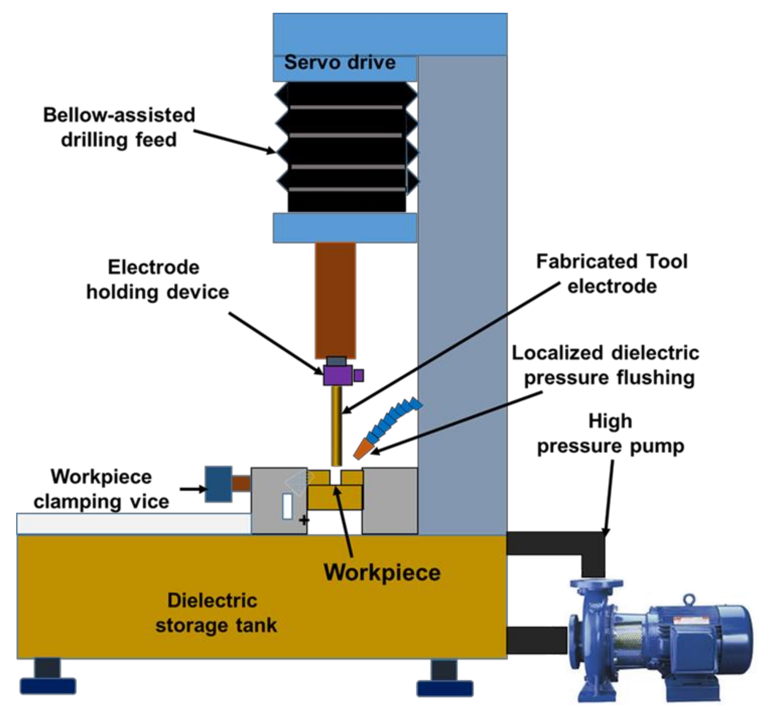 Figure 1. Schematic representation of micro-spark-erosion machining (µ-SEM) setup for drilling.
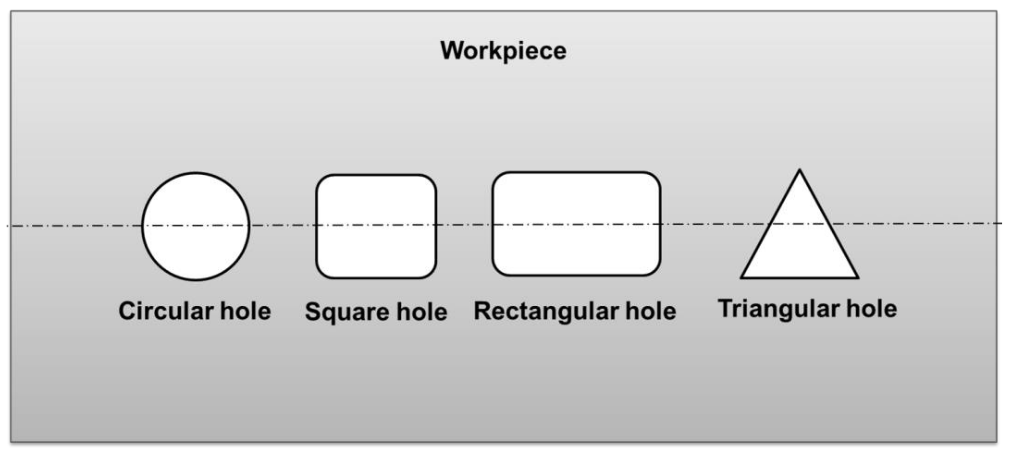 Figure 2. Types of holes that can be fabricated by the micro-spark-erosion machining (µ-SEM) process.
Micro spark erosion machining (µ-SEM) for meso and microhole drilling using hollow rotating tool electrodes is popularly known as micro spark erosion drilling (µ-SED). Figure 3 presents the schematic diagram of a µ-SED setup. Usually, µ-SED is adopted to drill fine holes (i.e., meso and micro-sized holes) in difficult-to-machine materials that are not possible to drill by traditional drilling methods. µ-SED is a non-traditional drilling method that fabricates deep and tiny holes. µ-SED can drill high aspect ratio circular and of complex geometry fine holes. µ-SED is a method of drilling fine holes on difficult-to-machine materials by recurring electric pulsed discharges or sparks, which are generated between the workpiece and rotary hollow electrode that eventually melt and vaporize the workpiece for hole making [15][16]. The basic components are (i) multi-axes worktable; (ii) rotary spindle drill chuck or collet system for holding electrodes; (iii) electrode guides made of ceramic or diamond; (iv) DC power supply; (v) capacitor box; and (vi) dielectric circulation system (flow pump). Generally, precision circular hollow bars or tubular electrodes of brass, copper, and its alloys are used as tools to remove the materials from the workpiece during drilling fine holes. These electrodes have a single hole/passage or array of passages. Hollow electrodes are used for localized flushing and cooling purposes. The array of tubes is preferred to eliminate the formation of slugs inside the passage. The tool electrode is continuously rotated during the drilling of fine holes, which enables the removal of the eroded particles from the inter-electrodes gap (IEG) and accelerates the drilling process. The ceramic or diamond guide positions the electrode tip on the exact location of the workpiece to avoid drifting during the drilling of fine holes. It also eliminates the wobbling of the rotary electrode and thus minimizes the drilling of oversized fine holes. Deionized water or hydrocarbon oil (kerosene oil) is used as dielectric to flush away the eroded particles (also referred to as debris) during the drilling process. Usually, a DC power supply is used, in which positive (anode) and negative (cathode) poles are connected to the workpiece and electrode, respectively. The process parameters are pulse-on-time, pulse-off-time, peak current, gap voltage, capacitance, the rotational speed of the tool electrode, and dielectric flow rate. These parameters can be varied during drilling fine holes. The electrode materials, dielectric fluids, workpiece thickness, and aspect ratio are other parameters, but these parameters cannot be varied during the drilling operation.
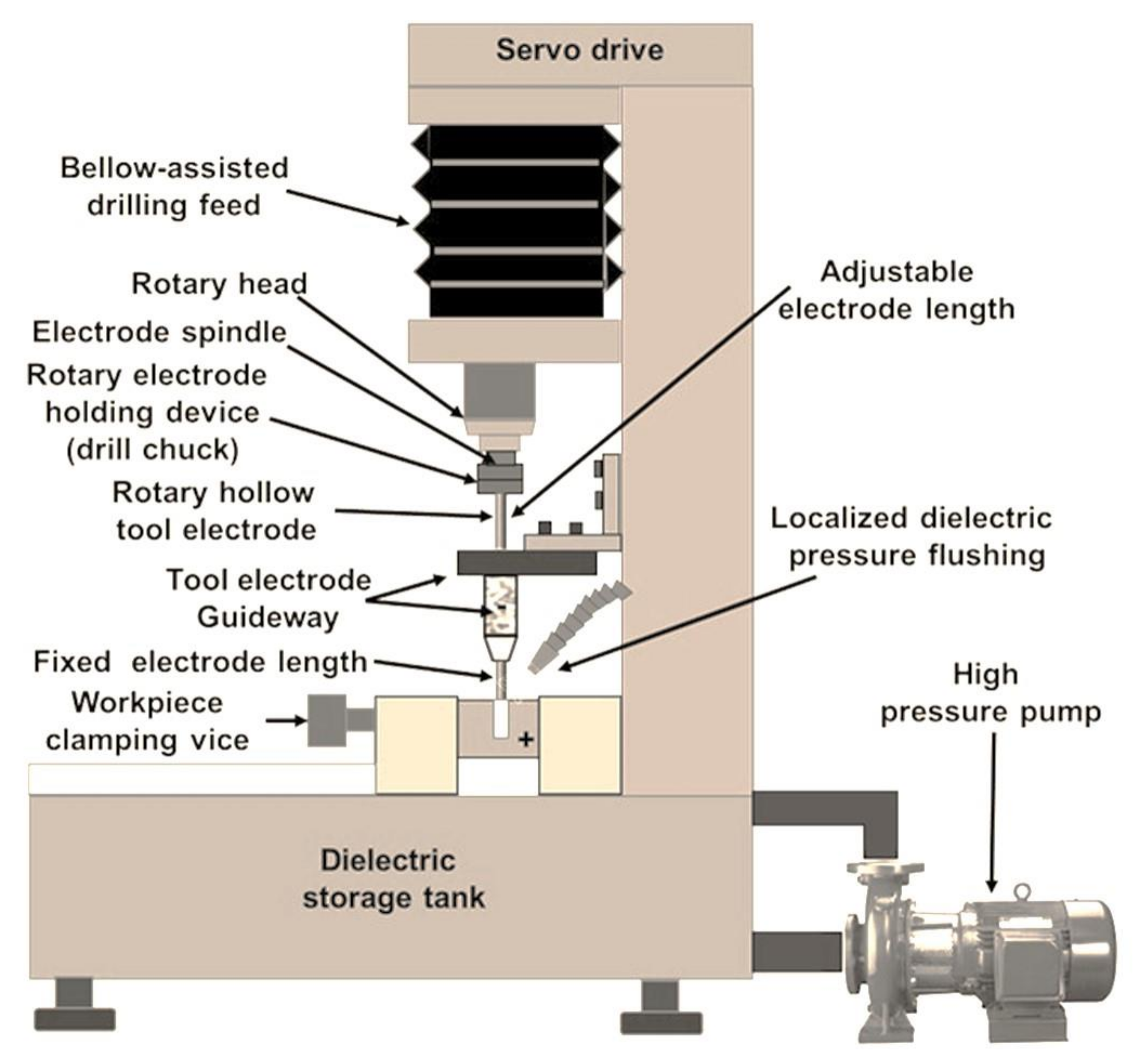 Figure 3. Schematic representation of micro-spark-erosion drilling (µ-SED) setup.
4. µ-SED Process and Working Principle
µ-SED process is similar to µ-SEM except hollow tool electrodes rotate continuously during the drilling process. In the µ-SED process, a vertical precision hollow electrode is firmly mounted into the tool chuck and attached to the spindle located along Z-axis. The spindle is attached with a direct current (DC) motor. The ceramic or diamond guide is used to position the electrode on the desired location of the workpiece for drilling the fine hole. The guide is located above the workpiece. The downward feed of the electrode is provided with the help of a servo drive that maintains a certain gap between the electrode and workpiece, in which sparks are generated and burn the materials from the workpiece to produce through or blind fine-hole. During drilling, the dielectric fluid continuously circulates through the rotary hollow electrode to flush away the eroded particle or debris from IEG and dissipates the heat produced by electric sparks. Only localized flushing is used in the µ-SED process. The drilling is completed after the desired depth of penetration on the workpiece by the rotary electrode and the electrode is retracted above the workpiece. The working principle of µ-SED is similar to the spark-erosion machining process (SEM) and its micro version (µ-SEM). The mechanism of material removal is based on thermoelectric erosion. A very strong electric field is formed at minimum IEG after supplying DC power to the workpiece and rotary electrode. The suspended microscopic particles in a dielectric fluid are accumulated around the location of the strongest electric field and form a conductive bridge across the electrodes gap. When the supply voltage is exceeded to dielectric breakdown voltage then the conductive bridge breaks due to excessive heat and temperature. Due to the collapse of the conductive bridge, sparks are generated between the interelectrode-gap. The material is removed from the workpiece due to melting and vaporization, and at the same time dielectric is flushed away from the eroded particles from the interelectrode-gap to ensure smooth drilling. The generation of sparks is continuously repeated until the drilling is up to the desired depth [17].
Figure 4, Figure 5, Figure 6, Figure 7 and Figure 8 depict some results of the completed and ongoing research work on the manufacturing of microholes on the rectangular SS 304 plate and square SS 304 specimens by µ-SED at the University of Johannesburg. Figure 4 shows the array of microholes of 800 µm diameter fabricated on a 5 mm thick stainless steel (SS 304) plate by the µ-SED process, using a rotating hollow brass electrode of 800 µm diameter. These microholes were used for wire passages to manufacture the different types of miniature gears, such as spur gears, helical gears, bevel gears, spiral gears, and ratchet wheels with center-hole by wire spark erosion machining (WSEM) process [9][10][18][19][20]. The researchers manufactured all these gears by WSEM from SS 304 plate. Figure 5 shows the WSEM manufactured miniature ratchet wheel and rectangular SS 304 plate after manufacturing. Researchers have conducted an experimental study to fabricate the microhole at the center of a 5 mm thick and 5 mm square SS 304 specimen by the µ-SED process, using a rotating hollow brass electrode of 800 µm diameter as shown in Figure 6. Figure 7 depicts an optical image of microholes fabricated on a square SS 304 specimen by the µ-SED process. A scanning electron microscopic image of a mesohole fabricated by the SED process using a rotating hollow brass electrode of 3 mm diameter is shown in Figure 8.
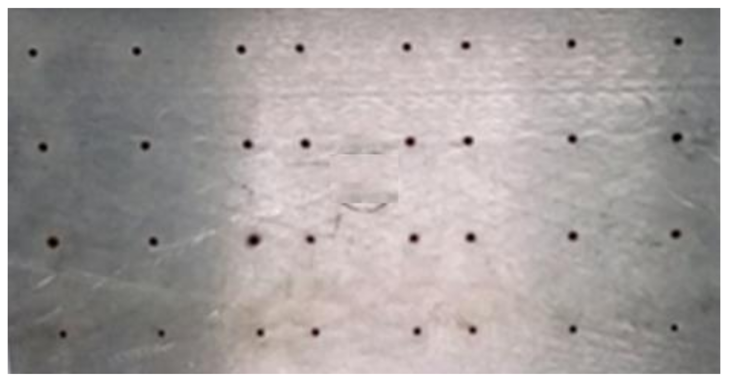 Figure 4. An array of microholes fabricated on SS 304 by micro spark-erosion drilling (µ-SED) process using a rotating brass hollow tool electrode of 800 µm diameter.
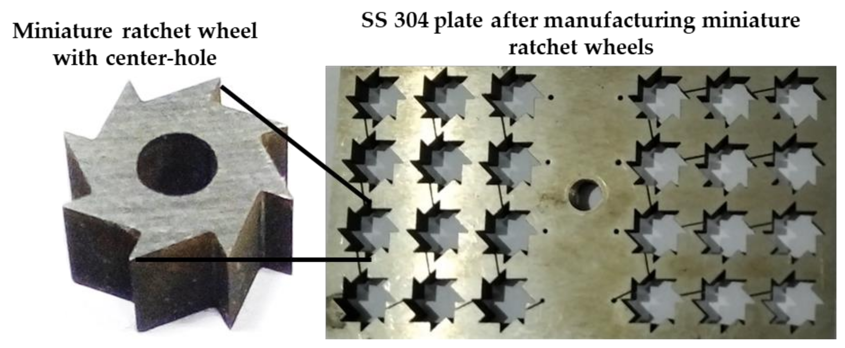 Figure 5. Miniature ratchet wheels manufactured by WSEM process from micro spark-erosion drilled SS 304 plate.
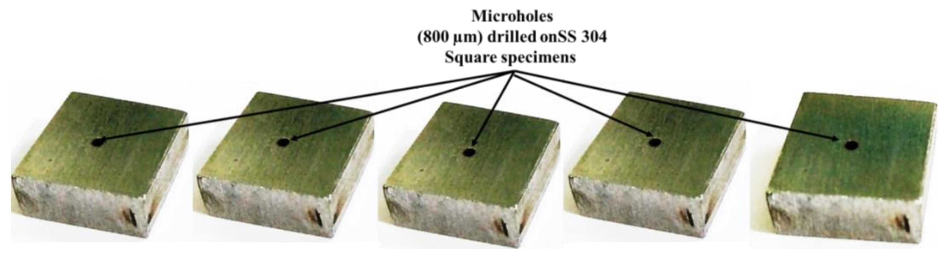 Figure 6. Microholes fabricated on square SS 304 specimens by micro spark-erosion drilling (µ-SED) process using rotating brass hollow tool electrode of 800 µm diameter.
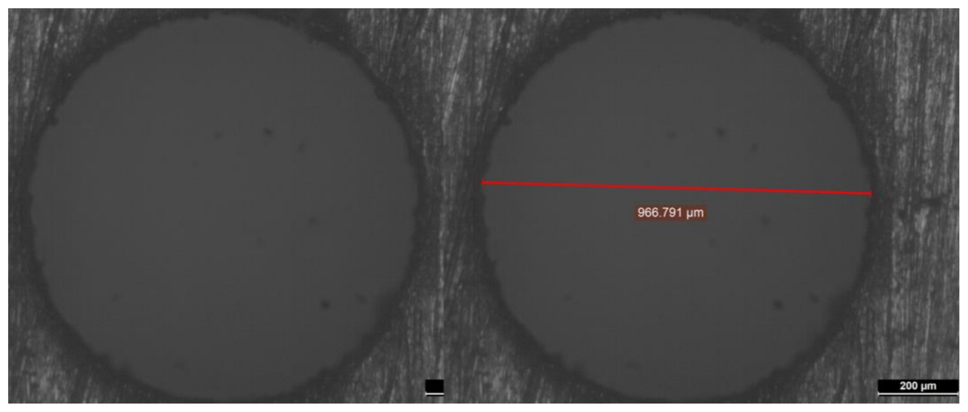 Figure 7. Optical images of microholes fabricated by micro spark-erosion drilling (µ-SED) process using rotating brass hollow tool electrode of 800 µm diameter.
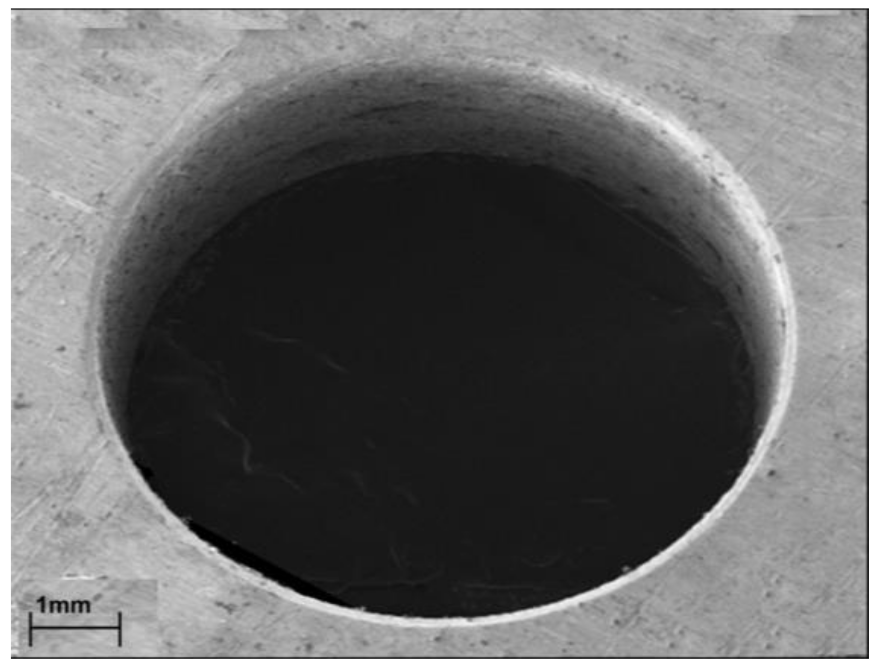 Figure 8. SEM images of mesohole fabricated by spark-erosion drilling (SED) process.
5. Process Parameters of µ-SED and Their Effect on the Responses
Figure 9 shows the process parameters and responses considered in the µ-SED process. The process parameters of µ-SED and µ-SEM are similar except the rotation of the tool electrode. The process parameters of µ-SED can be classified into two categories namely (i) electrical parameters; and (ii) non-electrical parameters. Electrical parameters are pulse-on-time, pulse-off-time, peak current, spark-gap voltage, pulse peak voltage, and capacitance; while tool rotational speed (TRS) of tool electrode, tool electrode feed, tool electrode diameter, drilling depth, workpiece material and thickness, and dielectric pressure/flow rate are non-electrical parameters. These parameters can be varied during drilling fine holes. The electrode materials, dielectric fluids, workpiece thickness, and aspect ratio are other important parameters but cannot be varied during the drilling operation. The higher values of pulse-on-time, peak current, pulse peak voltage, tool rotational speed, and tool electrode feed increase the material removal rate (MRR), electrode tool wear rate (TWR), and surface roughness (SR) of microholes. The higher values of pulse-off-time decrease the MRR, TWR, and SR of microholes. Tool electrode vibration due to loose clamping in the tool holder and loose clamping of the workpiece are responsible for the overcut and poor dimensional accuracy of microholes fabricated by µ-SED. Proper flushing is necessary for smooth drilling to achieve accurate and precise microholes. A higher dielectric flow rate is desirable to flush away the eroded particles from the drilling zone and avoid their redisposition on the drilled hole and the tool electrode surface. Redeposition of eroded particles is responsible for the formation of the recast layer and short circuiting [21][22][23]. Tool and workpiece materials also affect the MRR. Higher MRR can be achieved using workpiece and tool materials that are more electrically conductive. The high rotational speed is recommended for higher MRR and surface finish. µ-SED is more accurate and faster than µ-SEM process.
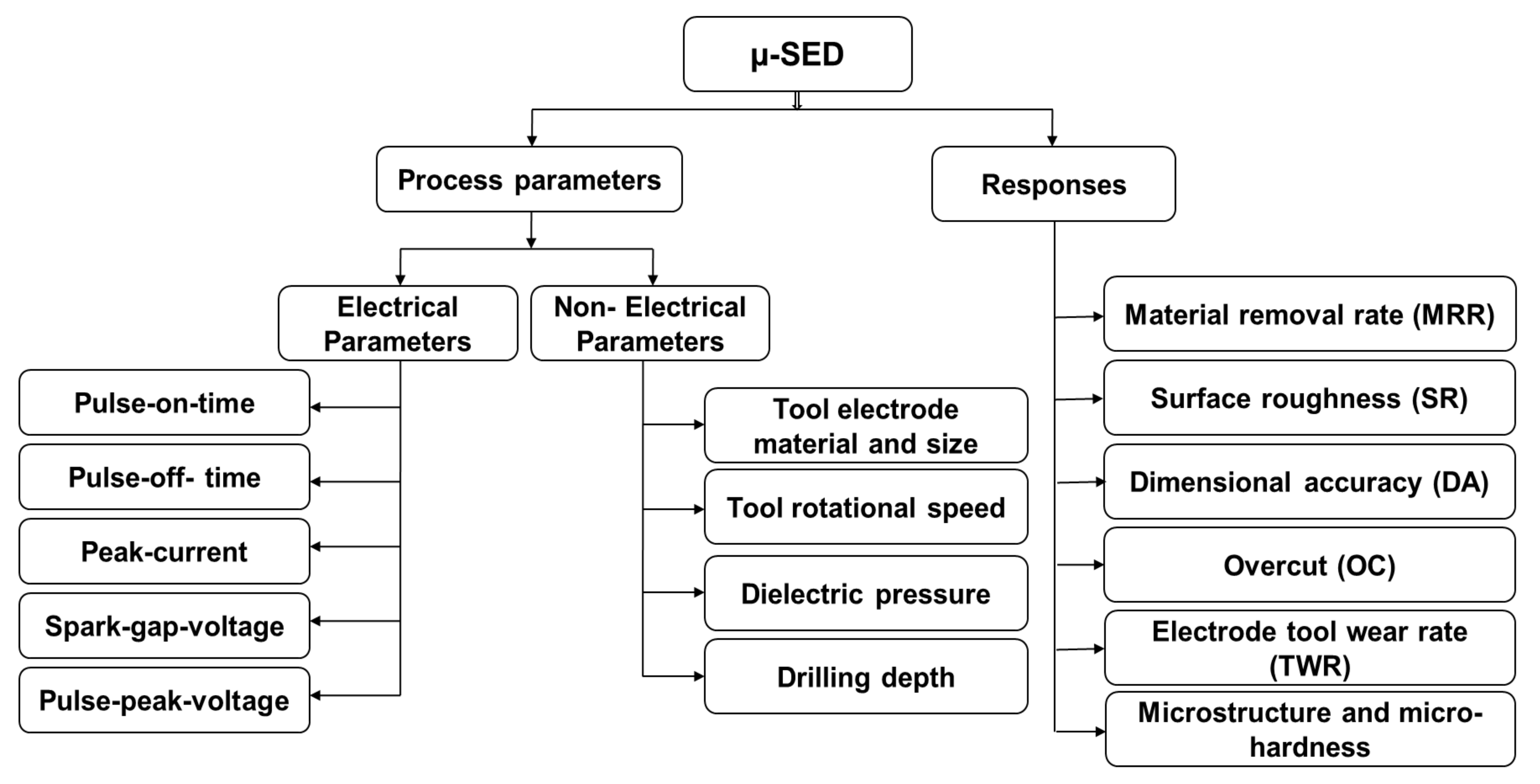 Figure 9. Micro spark-erosion drilling (µ-SED) process parameters and responses.
6. Applications and Advantages of the Micro Spark-Erosion Drilling Process
µ-SED is mostly used for quick, accurate, and fine deep-hole drilling applications. µ-SED can be found in several industrial applications, such as dental and medical, automobile, dies and moulds, electronics and telecommunication, and aerospace industries. The products and components which consist of microholes drilled by µ-SED are: (i) spray/injection nozzles; (ii) metal filters; (iii) fuel injectors; (iv) metallic filters; (v) dental tools; (vi) coolant holes; (vii) cooling manifolds; (viii) oil drain; and (ix) turbine blades.
The major advantages of µ-SED are (i) the ability to drill deep high-aspect-ratio (HAR) fine holes, (ii) the ability to produce accurate fine circular holes, (iii) no burr formation, thus eliminating the secondary finishing process, (iv) ability to drill high precision microscopic-holes, (v) the absence of mechanical stresses, (vi) the ability to produce holes on any kind of materials irrespective of their hardness, (vii) the ability to produce holes on thin and fragile materials; (viii) the ability to drill holes at a certain angle, (ix) the high material removal rate; and (x) unattended machining for a longer period.
Apart from the abovementioned advantages, µ-SED has certain limitations, such as the excessive tool electrode wear, not being suitable for non-circular holes, not being suitable for large-sized holes, the debris accumulated between IEG, and the abnormal sparks during drilling.
References
- Rajan, K.; Prabhushankar, N.; Nagarajan, N. A Review of Current Micro Drilling Processes. Int. J. Innov. Sci. Engg. Technol. 2016, 3, 60–64.
- Pathak, S.; Jain, N.K. Critical review of electrochemical honing (ECH): Sustainable and alternative gear finishing process. Part 1: Conventional processes and introduction to ECH. Trans. IMF 2017, 95, 147–157.
- Hasan, M.; Zhao, J.; Jiang, Z. A review of modern advancements in micro drilling techniques. J. Manuf. Process. 2017, 29, 343–375.
- Kanal, H.; Jain, A.; Grover, V. Micro Drilling and Drilling With Nano Materials: A Review. In Proceedings of the 4th National Conference on Advancements in Simulation & Experimental Techniques in Mechanical Engineering, Chennai, India, 3–4 May 20017; pp. 45–49.
- Singh, P.; Pramanik, A.; Basak, A.K.; Prakash, C.; Mishra, V. Developments of non-conventional drilling methods—A review. Int. J. Adv. Manuf. Technol. 2020, 106, 2133–2166.
- Wang, K.; Duan, W.; Mei, X.; Wang, W. Study on recast phenomenon in processing of micro-hole with millisecond laser. Adv. Mater. Res. 2012, 459, 315–319.
- Jain, N.K.; Chaubey, S.K. Review of Miniature Gear Manufacturing. In Comprehensive Materials Finishing; Chapter 1.17; Hashmi, M.S.J., Ed.; Elsevier: Oxford, UK, 2016; Volume 1, pp. 504–538.
- Chaubey, S.K.; Jain, N.K. State-of-art review of past research on manufacturing of meso and micro cylindrical gears. Precis. Eng. 2018, 51, 702–728.
- Chaubey, S.K.; Jain, N.K. Capabilities evaluation of WSEM, milling and hobbing for meso-gear manufacturing. Mater. Manuf. Process. 2018, 33, 1539–1548.
- Chaubey, S.K.; Jain, N.K. Analysis and multi-response optimization of gear quality and surface finish of meso-sized helical and bevel gears manufactured by WSEM process. Precis. Eng. 2019, 55, 293–309.
- Davis, J.R. Gear Materials, Properties, and Manufacture; ASM International: Geauga County, OH, USA, 2005.
- Jain, V.K. Advanced Machining Processes; Allied Publishers: New Delhi, India, 2002.
- Benedict, G.F. Nontraditional Manufacturing Processes; Marcel Dekker Inc.: New York, NY, USA, 1987; ISBN 0-8247-7352-7.
- Pandey, P.C.; Shan, H.S. Modern Machining Processes; Tata McGraw Hill Education PVT Ltd.: New Delhi, India, 2013.
- Khilji, I.A.; Saffe, S.N.B.M.; Pathak, S.; Ţălu, S.; Kulesza, S.; Bramowicz, M.; Reddy, V.J. Titanium Alloy Particles Formation in Electrical Discharge Machining and Fractal Analysis. JOM J. Miner. Met. Mater. Soc. 2022, 74, 448–455.
- Rajamanickama, S.; Prasannab, J. Taperness and Linear Wear Rate Analysis of High Aspect Ratio EDM Meso-Holes in Ti-6Al-4V. In Proceedings of the IOP Conference Series: Materials Science and Engineering, Telangana, India, 13–14 July 2018; Volume 455, pp. 1–11.
- Chaubey, S.K.; Singh, S.; Singh, A. Some investigations into machining of AISI D2 tool steel using wire electro discharge machining (WEDM) process. Mater. Today Proc. 2018, 5, 24347–24357.
- Gupta, K.; Jain, N.K.; Chaubey, S.K. Exploring wire-EDM for manufacturing the high quality meso-gears. Proc. Mat. Sci. 2014, 5, 1755–1760.
- Chaubey, S.K.; Jain, N.K.; Gupta, K. A Comprehensive Investigation on Development of Lightweight Aluminium Miniature Gears by Thermoelectric Erosion Machining Process. Micromachines 2021, 12, 1230.
- Chaubey, S.K.; Gupta, K.; Jain, N.K. Developing Spiral-Conical Gears for Microsystems by Wire-assisted Electrical Discharge Machining. Key Eng. Mat. 2022, 910, 421–435.
- Muthuramalingam, T.; Saravanakumar, D.; Babu, L.G.; Phan, N.H.; Pi, V.N. Experimental Investigation of White Layer Thickness on EDM Processed Silicon Steel Us-ing ANFIS Approach. Silicon 2020, 12, 1905–1911.
- Muthuramalingam, T.; Phan, N.H. Experimental investigation of white layer formation on machining silicon steel in PMEDM process. Silicon 2021, 13, 2257–2263.
- Muthuramalingam, T. Measuring the influence of discharge energy on white layer thickness in electrical discharge machining process. Measurement 2019, 131, 694–700.
More
Information
Subjects:
Engineering, Manufacturing
Contributors
MDPI registered users' name will be linked to their SciProfiles pages. To register with us, please refer to https://encyclopedia.pub/register
:
View Times:
2.8K
Revisions:
2 times
(View History)
Update Date:
04 Jul 2022
Table of Contents


Notice
You are not a member of the advisory board for this topic. If you want to update advisory board member profile, please contact office@encyclopedia.pub.
OK
Confirm
Only members of the Encyclopedia advisory board for this topic are allowed to note entries. Would you like to become an advisory board member of the Encyclopedia?
Yes
No
${ textCharacter }/${ maxCharacter }
Submit
Cancel
Back
Comments
${ item }
|
${ item.createdUser.fullName }
${ item.createdAt }
${ item.vote }
${ item.reply }
Delete
${ reply.createdUser.fullName }
${ reply.createdAt }
${ reply.vote }
Delete
There is no reply to this comment~
${ item.replyTextCharacter }/${ item.replyMaxCharacter }
Submit
Cancel
More
No more~
There is no comment~
${ textCharacter }/${ maxCharacter }
Submit
Cancel
${ selectedItem.replyTextCharacter }/${ selectedItem.replyMaxCharacter }
Submit
Cancel
Confirm
Are you sure to Delete?
Yes
No