Your browser does not fully support modern features. Please upgrade for a smoother experience.
Submitted Successfully!
 +1 credit
Thank you for your contribution! You can also upload a video entry or images related to this topic.
For video creation, please contact our Academic Video Service.
Video Upload Options
We provide professional Academic Video Service to translate complex research into visually appealing presentations. Would you like to try it?
Cite
If you have any further questions, please contact Encyclopedia Editorial Office.
Beake, B. Nano-, Micro- and Macro-Scale Impact Tests. Encyclopedia. Available online: https://encyclopedia.pub/entry/24226 (accessed on 25 June 2026).
Beake B. Nano-, Micro- and Macro-Scale Impact Tests. Encyclopedia. Available at: https://encyclopedia.pub/entry/24226. Accessed June 25, 2026.
Beake, Ben. "Nano-, Micro- and Macro-Scale Impact Tests" Encyclopedia, https://encyclopedia.pub/entry/24226 (accessed June 25, 2026).
Beake, B. (2022, June 20). Nano-, Micro- and Macro-Scale Impact Tests. In Encyclopedia. https://encyclopedia.pub/entry/24226
Beake, Ben. "Nano-, Micro- and Macro-Scale Impact Tests." Encyclopedia. Web. 20 June, 2022.
Copy Citation
Impact resistance is critical in many applications of coating systems involving highly loaded mechanical contact. Nano-impact testing utilises the depth-sensing capability of a multifunctional nanomechanical test system (NanoTest system, Micro Materials Ltd., Wrexham, UK) to perform impact testing at strain rates that are several orders of magnitude higher than those in quasi-static indentation tests.
nano-impact
micro-impact
fatigue
fracture
1. Introduction
Impact resistance is critical in many applications of coating systems involving highly loaded mechanical contact. These include automotive and aero-engine components and interrupted high-performance machining operations where intermittent high strain rate contact occurs [1][2][3]. In a diesel engine system, diamond-like carbon (DLC) coatings are deposited on many components in the powertrain, including fuel injectors, tappets, pistons, and piston rings, where they can be subjected to repetitive impacts in service [2]. In a gas turbine engine, high-temperature erosion of the thermal barrier coatings that protect the underlying superalloy turbine blades is a key factor lowering service life and restricting operating temperatures.
Cyclic impact tests are used as model tests for assessing coating durability under dynamic loading [4][5][6]. Bulk materials and coatings systems often undergo fatigue deformation mechanisms in the multi-cycle tests that are not observed in single-cycle tests [7][8]. In an impact test on a coated system, the test severity and positions of peak impact-induced stresses relative to the coating–substrate interface can be controlled by varying the impact energy and the geometry of the test probe. Fatigue mechanisms can vary with the ratio of coating thickness t to the indenter radius R [9][10] (t/R), so it can be very useful to perform impact tests with different contact sizes to obtain data over a range of t/R. Therefore, macro-scale, micro-scale and nano-scale impact tests have been developed. The differences between them and how these influence the observed behaviour is discussed in more detail in later sections. Deformation and failure mechanisms depend on applied load and indenter sharpness. t/R values are very low (≈0.001) in macro-scale tests of thin physical vapour deposition (PVD) coatings with cemented carbide or hardened steel spherical indenters with 1–3 mm end radius. The peak von Mises stresses that result in plastic deformation are located deep into the substrate, and hence, the fatigue behaviour can be strongly influenced by the substrate properties [1][4][5][6][7][11]. Although they can be useful, macro-scale impact tests have some limitations. An alternative approach to determining coating fatigue resistance is to perform nano-scale impact tests at higher t/R with much sharper probes. These accelerated tests are of much shorter duration than macro-scale tests and subject coatings to more severe conditions that replicate the high stresses generated in actual operating conditions. The position of peak von Mises stresses relative to the coating-substrate interface is completely different in the nano- and macro-scale tests. Nano-impact tests are very sensitive to small differences in coating properties and have shown excellent correlation to coating performance in applications. In particular, there have been many studies on Al-rich (Ti,Al)N-based PVD coatings on cemented carbide that have shown strong correlation between the wear of coated tools in high-speed machining applications and the fracture resistance found in the nano-impact test [12][13][14][15][16][17][18][19][20][21][22][23].
Nano-impact testing utilises the depth-sensing capability of a multifunctional nanomechanical test system (NanoTest system, Micro Materials Ltd., Wrexham, UK) to perform impact testing at strain rates that are several orders of magnitude higher than those in quasi-static indentation tests [24][25][26][27][28][29]. Although nano-impact is the most common terminology, the technique was originally termed micro-impact [30] and has also been described as impact indentation or impulse impact. The small scale tests provide more localised assessment of impact resistance. They have potential advantages in high throughput, automation and surface sensitivity, so they are particularly suited to thin coatings/small volumes and in investigating the influence of nano/microstructure on performance.
To bridge the gap in t/R between the nano- and macro-ranges, the micro-impact test, involving higher loads and larger probe sizes than in nano-impact, has been developed as an instrumented accelerated test sensitive to coating and substrate together where stresses can be concentrated near interface(s) in the system [31][32][33][34][35][36][37]. In the micro-impact test, coating and substrate deformation is important, and coatings can be subjected to high bending stresses. The importance of the strain rate on the fatigue failure of coatings has been highlighted by Bouzakis and co-workers, with even only a relatively modest increase in strain rate decreasing the fatigue endurance limit of Al0.6Ti0.4N-coated WC-Co [38]. The high strain rate contact in nano- and micro-impact tests can provide closer simulation of the performance of coatings systems under highly loaded intermittent contact and the evolution of wear under these conditions than tests at a lower strain rate.
2. Nano-Impact—Experimental Setup, Test Basics and Test Metrics
In the nano-impact test, a diamond indenter is withdrawn to a set distance from the sample surface and then rapidly accelerated to produce a high strain rate impact event. The depth-sensing capability of a commercial nanoindentation system (NanoTest, Micro Materials Ltd., Wrexham, UK) is used to monitor the degradation of surface from repeated localised stresses at high rates of strain, which are orders of magnitude higher than in normal (quasi-static) nanoindentation. The configuration is shown schematically in Figure 1a.
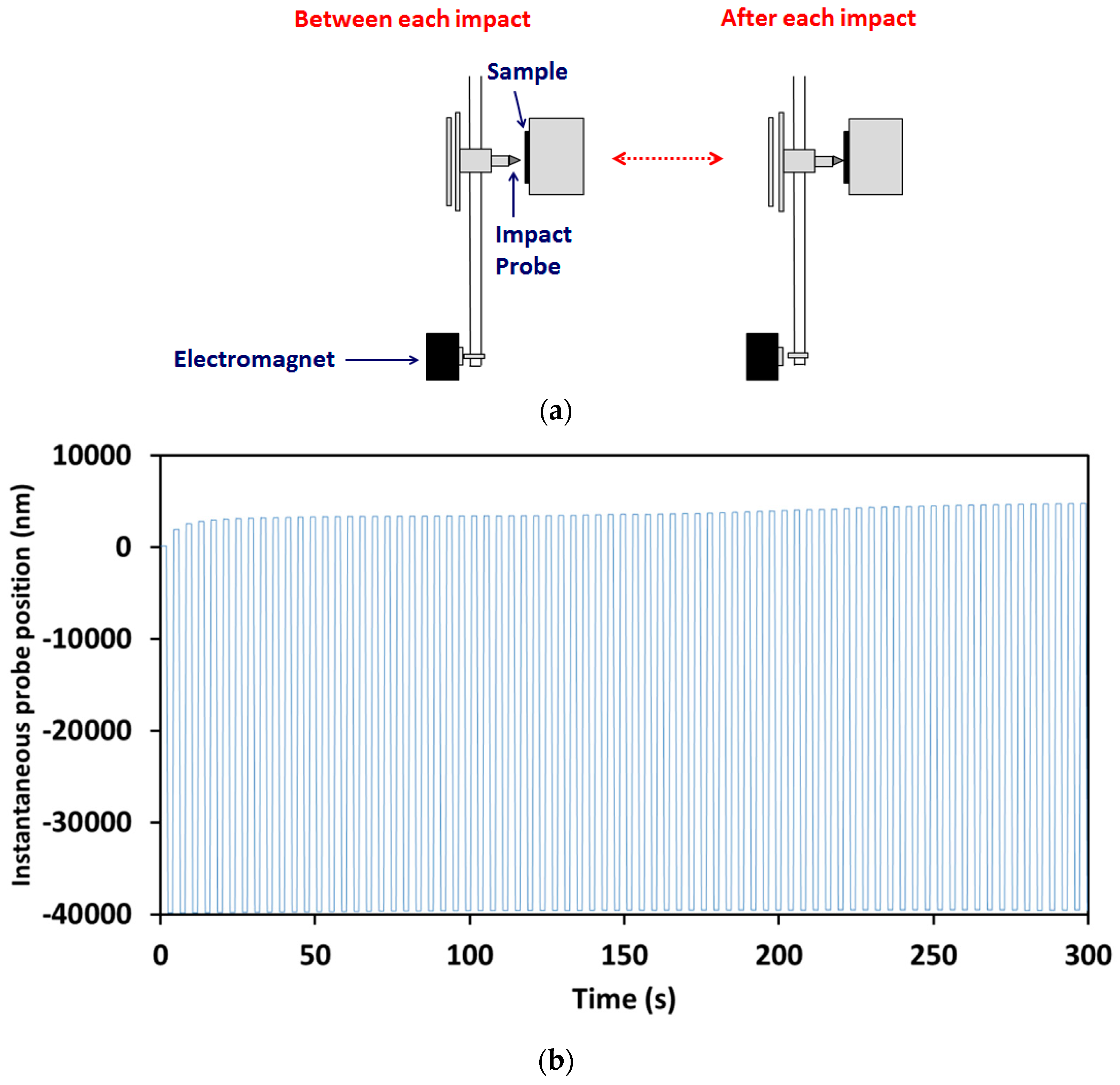 Figure 1. (a) Schematic representation of experimental configuration for repetitive nano-impact test. (b) Example of instantaneous probe position in a repetitive micro-impact test.
An initial surface contact by the impact probe under a minimum contact load determines the depth zero at the beginning of the nano-impact test experiment. The actuated (static) coil force is then applied, producing elastoplastic deformation by indentation. The corresponding initial indentation depth under load, h0, which includes elastic and plastic deformation, is used to confirm that the depth zero is measured correctly and the test did not impact in an anomalous region of the surface. Repetitive contacts are produced by electromagnetic actuation where the impact probe is rapidly withdrawn from the surface (e.g., to 10 μm above the surface, as shown schematically on the left-hand side of Figure 1b) and then accelerated over this distance to impact the surface (right-hand side of Figure 1b), producing true high strain rate impact events (see also Figure 2) where the probe leaves the surface between each subsequent impact. The under-load impact depth, h, is always larger than h0, as the dynamic impact force is significantly larger than the static impact load, due to inertia. Once the probe comes to rest, it is retracted, and with periodic actuation, the surface re-impacted at the same position at a set frequency, typically at 4 s intervals, to produce a cyclic impact test. The position of the impacting diamond probe under load is recorded throughout the test, allowing the progression of damage to be monitored cycle by cycle. An example is shown in Figure 1b.
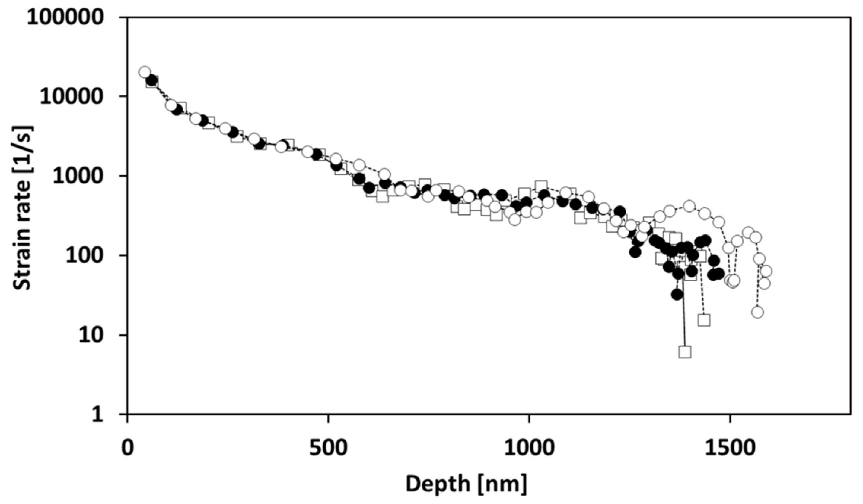 Figure 2. Strain rate in a nano-impact test on alumina with a cube corner indenter at 5 mN.
Several researchers have shown that the strain rate at contact in the nano-impact test can be extremely high, typically in the region of 104–105 s−1 [26][27][28][39][40]. To illustrate this, Figure 2 shows how the strain rate varies with time during a single impact event on a bulk alumina sample when impacted by a cube corner diamond probe (three repeats are shown). Although the strain rate reduces after contact, it remains at a high level throughout the majority of the impact event.
Experimental parameters such as the test probe geometry, applied load, acceleration distance and the total number of impact cycles and their frequency are user-controlled in the nano-impact test to alter the severity of the test and its duration. A cube corner diamond indenter (with a small end radius of ≈50 nm) has been the most popular choice of impact probe, as its geometry produces high contact strain, which is beneficial in driving impact-induced fracture within a short test time. The applied load and accelerating distance control the impact energy delivered to the sample. Typical nano-impact test parameters that have been used for testing hard coatings are: (i) cube corner diamond impact probe, (ii) 90° impact angle, (iii) 25–150 mN applied load, (iv) 15 μm accelerating distance, (v) 0.25 Hz impact frequency, (vi) 300 s test duration (i.e., 75 impacts in total), (vii) 5–10 repeat tests at each load, and (viii) normal laboratory temperature (e.g., 22 °C). The general procedure for micro-impact tests is the same.
Qin and co-workers [29] have split the impact process into three stages: (i) acceleration, (ii) indentation, and (iii) rebound. High-resolution analysis of probe depth vs. time data is used to determine a range of metrics from single impacts including (i) coefficient of restitution (Vin/Vout) and (ii) from knowledge of the effective mass of the pendulum, fractional potential energy (KEin/KEout) [41]. Analysis of single nano-impacts [29] provided an estimate of the fraction of the impact energy transferred to the sample as ≈0.7 and the fraction lost through losses to the system, i.e., transmission into the pendulum, vibration, and air damping as ≈0.3.
The response of a material to repetitive contact in the nano-impact test depends on its ductility or brittleness. On a ductile material, there is a gradual increase in probe penetration depth. The rate of depth increase slows with continued impacts, particularly for strongly work-hardening materials. In contrast, for a brittle material, there are often several abrupt increases in probe depth during the test due to cohesive and/or interfacial failures. A typical example on a coating system is shown in Figure 3. At 50 mN, there was no clear failure, but at higher loads, the abrupt increases due to fracture are clear.
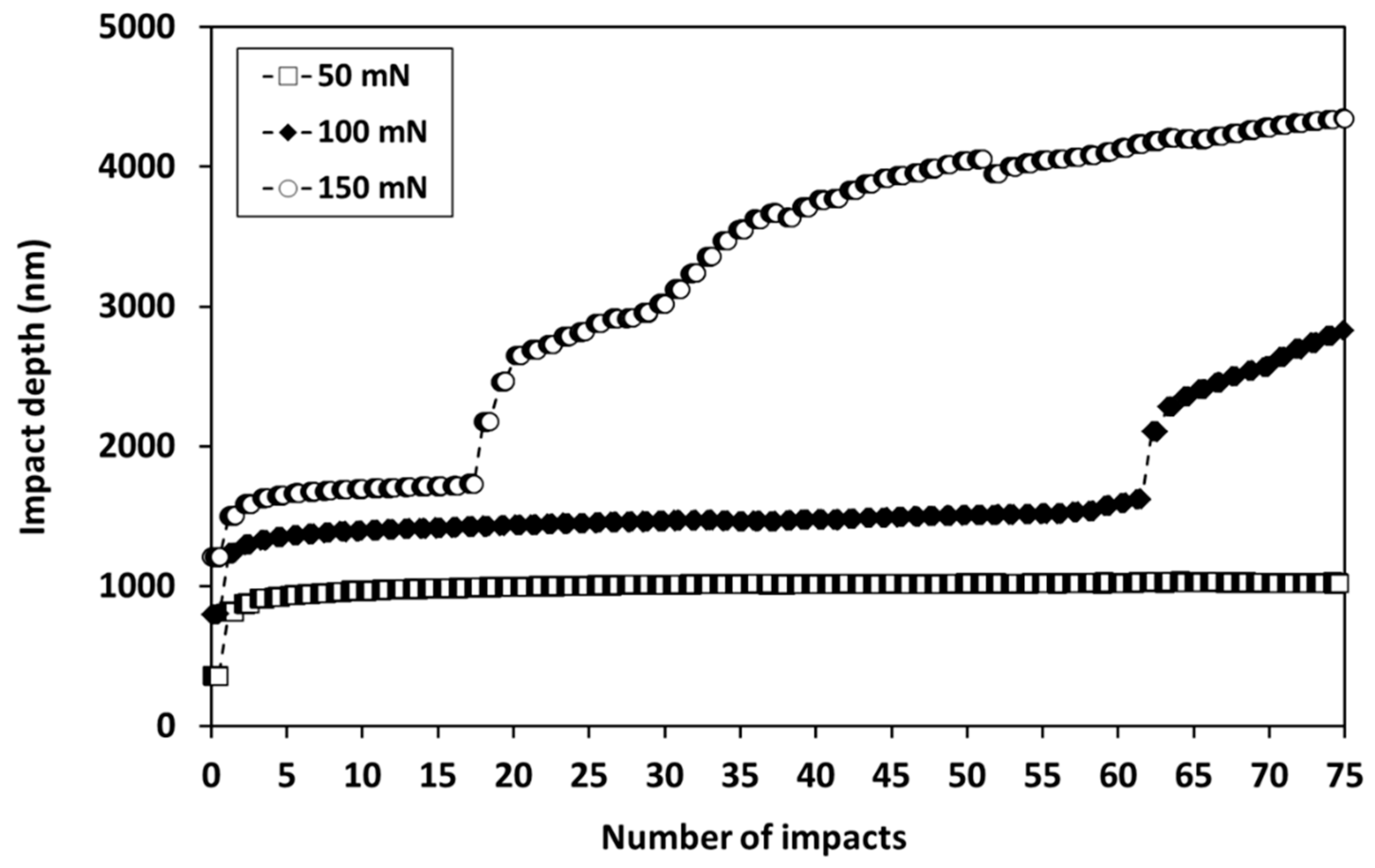 Figure 3. Variation in probe depth with number of impacts in nano-impact tests at 50–150 mN on Ti0.25Al0.65Cr0.1N PVD coating on cemented carbide with a sharp cube corner indenter.
Since it is trivial to set up multiple tests in an automated schedule, typically, multiple replicate tests are performed at different positions (e.g., in a grid array) on the sample surface to improve the statistical significance of the results. The impact resistance of different coatings can be assessed by the number of impacts required for failure to occur in 50% of the tests. Rebound impacts are essentially elastic [42] so that only the initial impact in each cycle is counted. Failure probability can be estimated by ranking the number of impacts-to-failure events in order of increasing fatigue resistance and then assigning a probability of failure to the nth ranked failure event in a total sample size of N, according to Equation (1), in an analogous approach to the treatment of distributions of failure stresses in Weibull statistics.
P(f) = n/(N + 1)
By combining failure probability data at different loads, a plot of the number of impacts required for failure to occur in 50% of tests vs. the impact force can be obtained. Failure in the nano-impact test can be strongly load-dependent. As an example, Figure 4 illustrates how the failure probability changes with load and number of impacts for an 80 nm ta-C coating on Si when impacted by a spherical indenter with a 4.6 μm end radius [43].
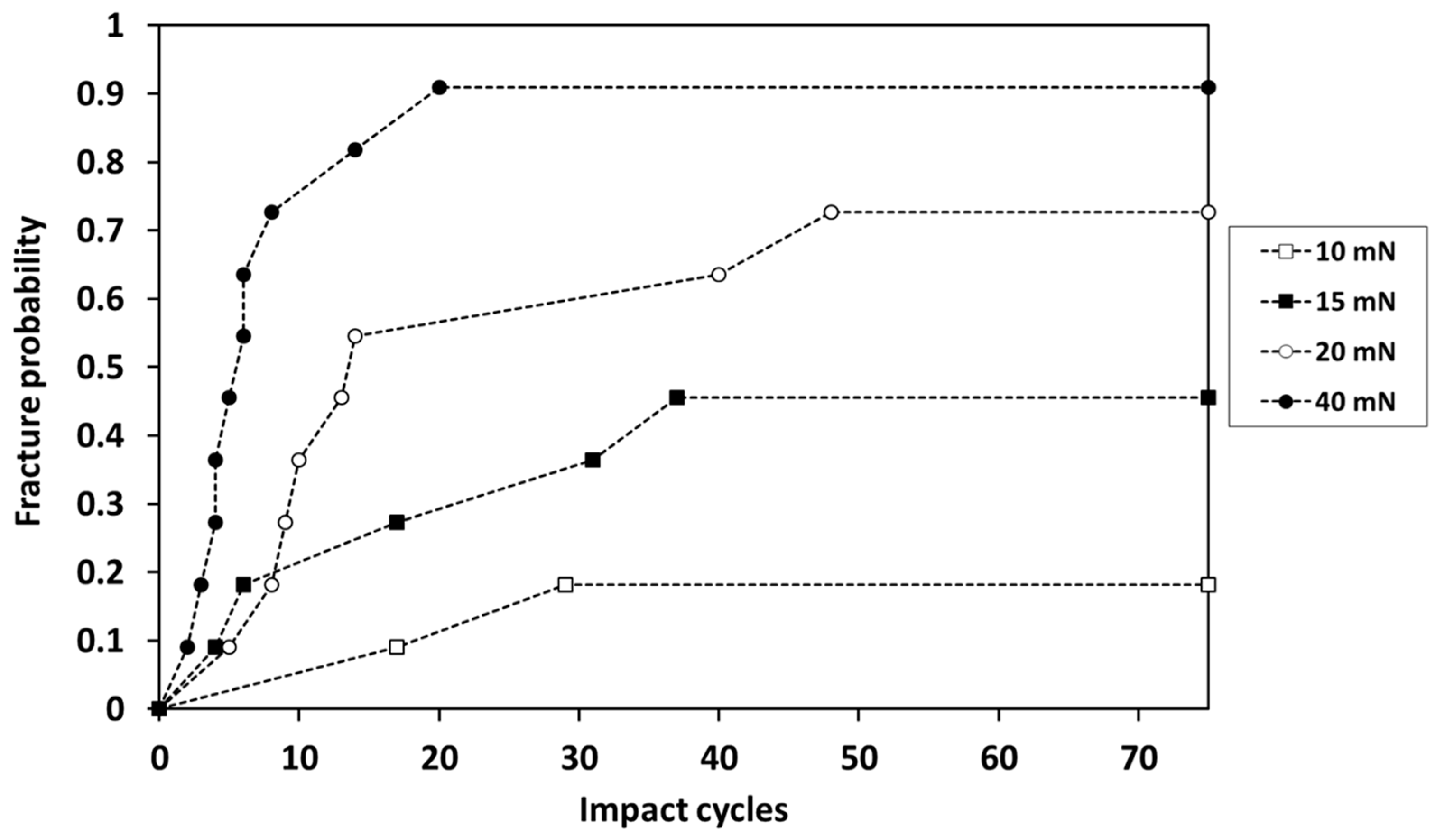 Figure 4. Failure probability vs. load for 80 nm ta-C on Si.
Several methods have been used to confirm that the abrupt changes in depth (as shown in Figure 3) are due to the onset of fracture. Jennett and Nunn [41] have used high-resolution analysis to monitor the change in fractional potential energy absorbed with continued impacting, showing a marked increase in energy absorbed for the impacts that resulted in abrupt increases in probe depth. In nano-impact tests on the bulk ceramic materials, alumina and partially stabilised zirconia, simultaneous acoustic emission (AE) detection has been used to reveal which impacts cause cracking [44][45]. Although there was a correlation between impacts that caused a large increase in depth being accompanied by bursts of AE, the in situ monitoring of AE revealed a more complex behaviour with crack systems developing over several impacts before a larger burst of AE for the impact resulting in material removal under the impact probe. Shi and co-workers [46] used high-resolution data acquisition of single nano-impacts on CrN to reveal changes in depth–time data when fracture occurred. In cyclic impact, more stochastic behaviour is observed from the onset of cracking. An indirect but practically useful indication of fracture is the onset of variability in depth vs. number of impacts in repeat tests [43]. When there was no fracture in any of the tests, the reproducibility in probe depth was typically very good. Higher variability begins once fracture occurs after a certain number of impacts in some tests but not others.
3. Comparison between Nano-, Micro- and Macro-Scale Impact Tests
The general procedure for nano- and micro-impact tests is the same. In micro-impact tests on hard coatings, the experimental parameters are typically the same except for accelerating distance, applied load and probe geometry. The accelerating distance is typically set at 40 µm so that differences in impact energy are obtained by altering the applied load (0.5–5 N). Sphero-conical diamond test probes with end radii of 8–100 μm have been most commonly used [36][47][48]. The impact energy is given by the product of the impulse force and accelerating distance. Since the accelerating distance is typically kept constant, it is common to report data in terms of the actuated impact force. Due to higher forces and accelerating distances, the energy supplied in micro-impact is typically from ×100 to ×1000 greater than in the nano-impact test, which enables spherical probes to be used effectively, causing fracture rapidly.
Typical experimental parameters in each type of test are summarised in Table 1. Although the principles behind nano-/micro- and macro-scale impact tests are common, there is a fundamental difference of approach in the nano-/micro- tests, which are depth-sensing, as the change in depth under load is monitored throughout the test with a capacitive sensor, and the macro-impact tests, which are not depth-sensing. Instead, coating durability in macro-scale impact tests has been assessed by post-test evaluations of damage such as crater volume [49] or failed-area ratio (defined as area of substrate exposure divided by the total contact area) [4][50]. Nano- and micro-impact tests are accelerated tests that are typically much shorter and probe coating system behaviour under more severe conditions where there is greater coating strain. Detailed information on the fatigue failure mechanisms in nano/micro-impact tests is obtained through setting up automated arrays of rapid repeat tests at different loads (e.g., 5–10 repeats per load) with cycle-by-cycle monitoring of the damage providing a precise measure of the number of impact cycles to coating failure in each test.
Table 1. Comparison between nano-, micro- and macro-scale impact test techniques (1).
| - | Nano-Impact | Micro-Impact | Macro-Impact |
|---|---|---|---|
| Depth sensing | Y | Y | N |
| Accurate time-to-failure recorded | Y | Y | N |
| Test duration | 1–60 min (2) | 1–60 min (2) | Extended duration |
| Number of impact cycles | 15–900 | 15–900 | 102–106 |
| Test probe material | Diamond | Diamond | WC-Co, hardened steel, Si3N4 |
| Test probe radius, R | ≈50 nm | 5–100 µm | 1–3 mm |
| t/R | ≈10 | ≈0.1 | ≈0.001 |
| Sensitivity to coating mechanical properties | High | High | may be low |
| Sensitivity to adhesion | Medium | High | may be low |
| Automatic scheduling of multiple tests/tests on multiple samples | Y | Y | N |
| Applied load (N) | 0.001–0.2 | 0.1–5 | >>100 |
| Accelerating distance (μm) | 10–15 | 10–60 | can remain in contact |
The micro-impact test at higher t/R than macro-impact can be more sensitive to coating and substrate together, since stresses can be concentrated near interfaces in the coating system [31]. Beake, Liskiewicz and co-workers [31][32][33][34][35][36][37] have used this technique to investigate (i) impact resistance of hard carbon coatings on hardened tool steel [33][34][35][37] and (ii) PVD nitrides on WC-Co [31][32][36][37]. The impact energy in nano- and micro-impact tests is much lower than in the macro-scale tests, but critically, it is acting over a very small volume so that the resultant impact energy density is high. The size of the affected volume can be estimated by 2.4a × πa2, where a is the contact radius and 2.4a is the depth of the primary indentation zone [62][63]. In a study of micro-impact of TiAlCrN/NbN coatings, the calculated energy densities when using R = 8 or 20 μm probes were ≈2–4 GJ/m3, resulting in rapid fracture [36].
The potential advantages of studying coating fatigue resistance by nano- or micro-scale tests are the much shorter duration of the experiments compared to conventional, high-cycle macro-scale tests and impact-by-impact monitoring of the impact-induced deformation process that provides a precise record of the exact number of cycles to failure with detailed information on the fatigue failure mechanism. It is possible to use nano- or micro-impact testing to automatically build up complete S-N fatigue curves from single samples, enabling rapid screening to evaluate the performance of novel coating compositions and load-dependent deformation mechanisms to be evaluated.
References
- Knotek, O.; Bosserhoff, B.; Schrey, A.; Leyendecker, T.; Lemmer, O.; Esser, S. A new technique for testing the impact load of thin films: The coating impact test. Surf. Coat. Technol. 1992, 54–55, 102–107.
- Lawes, S.; Hainsworth, S.; Fitzpatrick, M. Impact wear testing of diamond-like carbon films for engine valve-tappet surfaces. Wear 2010, 268, 1303–1308.
- Bouzakis, K.-D.; Flocke, F.; Skordaris, G.; Bouzakis, E.; Geradis, S.; Katirtzoglou, G.; Makrimallakis, S. Influence of dry micro-blasting grain quality on wear behavior of TiAlN coated tools. Wear 2011, 271, 783–791.
- Bouzakis, K.-D.; Siganos, A.; Leyendecker, T.; Erkens, G. Thin hard coatings fracture propagation during the impact test. Thin Solid Films 2004, 460, 181–189.
- Bantle, R.; Matthews, A. Investigation into the impact wear behavior of ceramic coatings. Surf. Coat. Technol. 1995, 74–75, 857–868.
- Yoon, S.Y.; Yoon, S.-Y.; Chung, W.-S.; Kim, K.H. Impact-wear behaviors of TiN and Ti-Al-N coatings on AISI D2 steel and WC-Co substrates. Surf. Coat. Technol. 2004, 177–178, 645–650.
- Ramírez, G.; Mestra, A.; Casas, B.; Valls, I.; Martínez, R.; Bueno, R.; Góez, A.; Mateo, A.; Llanes, L. Influence of substrate microstructure on the contact fatigue strength of coated cold-work tool steels. Surf. Coat. Technol. 2012, 206, 3069–3081.
- Kim, D.K.; Jung, Y.-G.; Peterson, I.; Lawn, B. Cyclic fatigue of intrinsically brittle ceramics in contact with spheres. Acta Mater. 1999, 47, 4711–4725.
- Michler, J.; Blank, E. Analysis of coating fracture and substrate plasticity induced by spherical indentors: Diamond and diamond-like carbon layers on steel substrates. Thin Solid Films 2001, 381, 119–134.
- Bernoulli, D.; Wyss, A.; Raghavan, R.; Thorwarth, K.; Hauert, R.; Spolenak, R. Contact damage of hard and brittle thin films on ductile metallic substrates: An analysis of diamond-like carbon on titanium substrates. J. Mater. Sci. 2015, 50, 2779–2787.
- Bromark, M.; Hedenqvist, P.; Hogmark, S. The influence of substrate material on the erosion resistance of TiN coated steels. Wear 1995, 186–187, 189–194.
- Fox-Rabinovich, G.S.; Beake, B.D.; Veldhuis, S.C.; Endrino, J.L.; Parkinson, R.; Shuster, L.S.; Migranov, M.S. Impact of mechanical properties measured at room and elevated temperatures on wear resistance of cutting tools with TiAlN and AlCrN coatings. Surf. Coat. Technol. 2006, 200, 5738–5742.
- Beake, B.D.; Smith, J.F.; Gray, A.; Fox-Rabinovich, G.S.; Veldhuis, S.C.; Endrino, J.L. Investigating the correlation between nano-impact fracture resistance and hardness/modulus ratio from nanoindentation at 25–500 °C and the fracture resistance and lifetime of cutting tools with Ti1−xAlxN (x = 0.5 and 0.67) PVD coatings in milling operations. Surf. Coat. Technol. 2007, 201, 4585.
- Fox-Rabinovich, G.S.; Kovalev, A.I.; Aguirre, M.H.; Beake, B.D.; Yamamoto, K.; Veldhuis, S.C.; Endrino, J.L.; Wainstein, D.L.; Rashkovskiy, A.Y. Design and performance of AlTiN and TiAlCrN PVD coatings for machining of hard to cut materials. Surf. Coat. Technol. 2009, 204, 489–496.
- Beake, B.; Fox-Rabinovich, G.; Veldhuis, S.; Goodes, S. Coating optimisation for high-speed machining with advanced nanomechanical test methods. Surf. Coat. Technol. 2009, 203, 1919–1925.
- Fox-Rabinovich, G.S.; Beake, B.D.; Yamamoto, K.; Aguirre, M.H.; Veldhuis, S.C.; Dosbaeva, G.; Elfizy, A.; Biksa, A.; Shuster, L.S.; Rashkovskiy, A.Y. Structure, properties and wear performance of nano-multilayered TiAlCrSiYN/TiAlCrN coatings during machining of Ni-based aerospace superalloys. Surf. Coat. Technol. 2010, 204, 3698–3706.
- Fox-Rabinovich, G.; Yamamoto, K.; Beake, B.; Kovalev, A.; Aguirre, M.H.; Veldhuis, S.; Dosbaeva, G.; Wainstein, D.; Biksa, A.; Rashkovskiy, A. Emergent behavior of nano-multilayered coatings during dry high speed machining of hardened tool steels. Surf. Coat. Technol. 2010, 204, 3425–3435.
- Bouzakis, K.-D.; Michailidis, N.; Skordaris, G.; Bouzakis, E.; Biermann, D.; M’Saoubi, R. Cutting with coated tools: Coating technologies, characterization methods and performance optimization. CRIP Ann. Manuf. Technol. 2012, 61, 703–723.
- Skordaris, G.; Bouzakis, K.; Charalampous, P.; Bouzakis, E.; Paraskevopoulou, R.; Lemmer, O.; Bolz, S. Brittleness and fatigue effect of mono- and multi-layer PVD films on the cutting performance of coated cemented carbide inserts. CIRP Ann. Manuf. Technol. 2014, 63, 93.
- Beake, B.; Fox-Rabinovich, G. Progress in high temperature nanomechanical testing of coatings for optimising their performance in high speed machining. Surf. Coat. Technol. 2014, 255, 1021115.
- Skordaris, G.; Bouzakis, K.D.; Kotsanis, T.; Charalampous, P.; Bouzakis, E.; Breidenstein, B.; Bergmann, B.; Denkena, B. Effect of PVD film’s residual stress on their mechanical properties, brittleness, adhesion and cutting performance of coated tools. CIRP J. Manuf. Sci. Technol. 2017, 18, 145–151.
- Bouzakis, K.D.; Skordaris, G.; Bouzakis, E.; Kotsanis, T.; Charalampous, P. A critical review of characteristic techniques for improving the cutting performance of coated tools. J. Mach. Eng. 2017, 17, 25–44.
- Chowdhury, S.; Bose, B.; Yamamoto, K.; Veldhuis, S.C. Effect of interlayer thickness on nano-multilayer coating performance during high speed dry milling of H13 tool steel. Coatings 2019, 9, 737.
- Trelewicz, J.R.; Schuh, C.A. The Hall–Petch breakdown at high strain rates: Optimizing nanocrystalline grain size for impact applications. Appl. Phys. Lett. 2008, 93, 171916.
- Somekawa, H.; Schuh, C.A. High-strain-rate nanoindentation behavior of fine-grained magnesium alloys. J. Mater. Res. 2012, 27, 1295–1302.
- Wheeler, J.M. Nanoindentation under Dynamic Conditions. Ph.D. Thesis, University of Cambridge, Cambridge, UK, 2009.
- Rueda-Ruiz, M.; Beake, B.D.; Molina-Aldareguia, J.M. New instrumentation and analysis methodology for nano-impact testing. Mater. Des. 2020, 192, 108715.
- Rueda-Ruiz, M.; Beake, B.D.; Molina-Aldareguia, J.M. Determination of rate dependent properties in cohesive frictional materials by instrumented indentation. JOM 2022, 74, 2206–2219.
- Qin, L.; Li, H.; Shi, X.; Beake, B.D.; Xiao, L.; Smith, J.F.; Sun, Z.; Chen, J. Investigation on dynamic hardness and high strain rate indentation size effects in aluminium (110) using nano-impact. Mech. Mater. 2019, 133, 55–62.
- Beake, B.D.; Goodes, S.R.; Smith, J.F. Micro-impact testing: A new technique for evaluating fracture toughness, adhesion, erosive wear resistance and dynamic hardness. Surf. Eng. 2001, 17, 187.
- Beake, B.D.; Isern, L.; Endrino, J.L.; Fox-Rabinovich, G.S. Micro-impact testing of AlTiN and TiAlCrN coatings. Wear 2019, 418–419, 102–110.
- Beake, B.D.; Bird, A.; Isern, L.; Endrino, J.; Jiang, F. Elevated temperature micro-impact testing of TiAlSiN coatings produced by physical vapour deposition. Thin Solid Films 2019, 688, 137358.
- Beake, B.D.; Liskiewicz, T.W.; Bird, A.; Shi, X. Micro-scale impact testing—A new approach to studying fatigue resistance in hard carbon coatings. Tribol. Int. 2020, 149, 105732.
- McMaster, S.J.; Liskiewicz, T.W.; Neville, A.; Beake, B.D. Probing fatigue resistance in multi-layer DLC coatings by micro- and nano-impact: Correlation to erosion tests. Surf. Coat. Technol. 2020, 402, 126319.
- Beake, B.D.; McMaster, S.J.; Liskiewicz, T.W.; Neville, A. Influence of Si- and W- doping on micro-scale reciprocating wear and impact performance of DLC coatings on hardened steel. Tribol. Int. 2021, 160, 107063.
- Beake, B.; Bergdoll, L.; Isern, L.; Endrino, J.; Fox-Rabinovich, G.; Veldhuis, S. Influence of probe geometry in micro-scale impact testing of nano-multilayered TiAlCrN/NbN coatings deposited on WC-Co. Int. J. Refract. Met. Hard Mater. 2021, 95, 105441.
- Beake, B.; Isern, L.; Endrino, J.; Liskiewicz, T.; Shi, X. Micro-scale impact resistance of coatings on hardened tool steel and cemented carbide. Mater. Lett. 2021, 284, 129009.
- Bouzakis, K.; Maliaris, G.; Makrimallakis, S. Strain rate effect on the fatigue failure of thin PVD coatings: An investigation by novel impact tester with adjustable repetitive force. Int. J. Fatigue 2012, 44, 89–97.
- Faisal, N.; Ahmed, R.; Goel, S.; Fu, Y. Influence of test methodology and probe geometry on nanoscale fatigue failure of diamond-like carbon film. Surf. Coat. Technol. 2014, 242, 42–53.
- Zhang, H.; Li, Z.; He, W.; Ma, C.; Chen, J.; Liao, B.; Li, Y. Damage mechanisms evolution of TiN/Ti multilayer films with different modulation periods in cyclic impact conditions. Appl. Surf. Sci. 2021, 540, 148366.
- Jennett, N.M.; Nunn, J. High resolution measurement of dynamic (nano) indentation impact energy: A step towards the determination of indentation fracture resistance. Philos. Mag. 2011, 91, 1200–1220.
- Wheeler, J.; Dean, J.; Clyne, T. Nano-impact indentation for high strain rate testing: The influence of rebound impacts. Extrem. Mech. Lett. 2019, 26, 35–39.
- Shi, X.; Beake, B.D.; Liskiewicz, T.W.; Chen, J.; Sun, Z. Failure mechanism and protective role of ultrathin ta-C films on Si (100) during cyclic nano-impact. Surf. Coat. Technol. 2019, 364, 32–42.
- Ctvrtlik, R.; Tomastik, J.; Vaclavek, L.; Beake, B.D.; Harris, A.J.; Martin, A.S.; Hanak, M.; Abrham, P. High-resolution acoustic emission monitoring in nanomechanics. JOM 2019, 71, 3358–3367.
- Beake, B.D.; Ctvrtlik, R.; Harris, A.J.; Martin, A.S.; Vaclavek, L.; Manak, J.; Ranc, V. High frequency acoustic emission monitoring in nano-impact of alumina and partially stabilised zirconia. Mater. Sci. Eng. A 2020, 780, 139159.
- Shi, X.; Li, H.; Beake, B.D.; Bao, M.; Liskiewicz, T.W.; Sun, Z.; Chen, J. Dynamic fracture of CrN coating by highly-resolved nano-impact. Surf. Coat. Technol. 2020, 383, 125288.
- Beake, B.; Isern, L.; Harris, A.; Endrino, J. Probe geometry and surface roughness effects in microscale impact testing of WC-Co. Mater. Manuf. Proc. 2020, 35, 836–844.
- Beake, B.D.; Isern, L.; Bhattacharyya, D.; Endrino, J.L.; Lawson, K.; Walker, T. Nano- and micro-scale impact testing of zirconia, alumina and zirconia-alumina duplex optical coatings on glass. Wear 2020, 462–463, 203499.
- Cassar, G.; Banfield, S.; Wilson, J.A.-B.; Housden, J.; Matthews, A.; Leyland, A. Impact wear resistance of plasma diffusion treated and duplex treated/PVD-coated Ti–6Al–4V alloy. Surf. Coat. Technol. 2012, 206, 2645–2654.
- Zha, X.; Jiang, F.; Xu, X. Investigating the high frequency fatigue failure mechanisms of mono and multilayer PVD coatings by the cyclic impact tests. Surf. Coat. Technol. 2018, 344, 689–701.
- Antonov, M.; Hussainova, I.; Sergejev, F.; Kulu, P.; Gregor, A. Assessment of gradient and nanogradient PVD coatings under erosive, abrasive and impact wear conditions. Wear 2009, 267, 898–906.
- Lamri, S.; Langlade, C.; Kermouche, G. Damage phenomena of thin hard coatings submitted to repeated impacts: Influence of the substrate and film properties. Mater. Sci. Eng. A 2013, 560, 296–305.
- Batista, J.C.A.; Godoy, C.; Matthews, A. Impact testing of duplex and non-duplex (Ti,Al)N and Cr–N PVD coatings. Surf. Coat. Technol. 2003, 163–164, 353–361.
- Mo, J.L.; Zhu, M.H.; Leyland, A.; Matthews, A. Impact wear and abrasion resistance of CrN, AlCrN and AlTiN PVD coatings. Surf. Coat. Technol. 2013, 215, 170–177.
- Treutler, C.P.O. Industrial use of plasma-deposited coatings for components of automotive fuel injection systems. Surf. Coat. Technol. 2005, 200, 1969–1975.
- Bao, M.D.; Zhu, X.D.; He, J.W. Evaluation of the toughness of hard coatings. Surf. Eng. 2006, 22, 11–14.
- Zhu, X.; Dou, H.; Ban, Z.; Liu, Y.; He, J. Repeated impact test for characterisation of hard coatings. Surf. Coat. Technol. 2007, 201, 5493–5497.
- Ledrappier, F.; Langlade, C.; Vannes, A.-B.; Gachon, Y. Damage phenomena observed on PVD coatings subjected to repeated impact tests. Plasma Process. Polym. 2007, 4, 5835–5839.
- Ledrappier, F.; Langlade, C.; Gachon, Y.; Vannes, A.-B. Blistering and spalling of thin hard coatings submitted to repeated impacts. Surf. Coat. Technol. 2008, 202, 1789–1796.
- Qiu, L.; Zhu, X.; Lu, S.; He, G.; Xu, K. Quantitative evaluation of bonding strength for hard coatings by interfacial fatigue strength under cyclic indentation. Surf. Coat. Technol. 2017, 315, 303–313.
- Qiu, L.; Zhu, X.; He, G.; Xu, K. The repeated spherical indentation test: An efficient way to evaluate the adhesion of hard coatings. Surf. Eng. 2016, 32, 578–584.
- Kalidindi, S.; Pathak, S. Determination of the effective zero-point and the extraction of spherical nanoindentation stress–strain curves. Acta Mater. 2008, 56, 3523–3532.
- Pathak, S.; Kalidindi, S.R. Spherical nanoindentation stress–strain curves. Mater. Sci. Eng. R 2015, 91, 1–36.
More
Information
Contributor
MDPI registered users' name will be linked to their SciProfiles pages. To register with us, please refer to https://encyclopedia.pub/register
:
View Times:
1.2K
Revisions:
2 times
(View History)
Update Date:
21 Jun 2022
Table of Contents


Notice
You are not a member of the advisory board for this topic. If you want to update advisory board member profile, please contact office@encyclopedia.pub.
OK
Confirm
Only members of the Encyclopedia advisory board for this topic are allowed to note entries. Would you like to become an advisory board member of the Encyclopedia?
Yes
No
${ textCharacter }/${ maxCharacter }
Submit
Cancel
Back
Comments
${ item }
|
${ item.createdUser.fullName }
${ item.createdAt }
${ item.vote }
${ item.reply }
Delete
${ reply.createdUser.fullName }
${ reply.createdAt }
${ reply.vote }
Delete
There is no reply to this comment~
${ item.replyTextCharacter }/${ item.replyMaxCharacter }
Submit
Cancel
More
No more~
There is no comment~
${ textCharacter }/${ maxCharacter }
Submit
Cancel
${ selectedItem.replyTextCharacter }/${ selectedItem.replyMaxCharacter }
Submit
Cancel
Confirm
Are you sure to Delete?
Yes
No