Submitted Successfully!
To reward your contribution, here is a gift for you: A free trial for our video production service.
Thank you for your contribution! You can also upload a video entry or images related to this topic.
Version Summary Created by Modification Content Size Created at Operation
1 -- 6196 2022-06-09 18:04:36 |
2 format correct -11 word(s) 6185 2022-06-10 05:10:04 | |
3 format correct -19 word(s) 6166 2022-06-10 05:15:02 | |
4 format correct Meta information modification 6166 2022-06-13 08:48:54 |

Video Upload Options

Do you have a full video?

Confirm

Are you sure to Delete?
Cite
If you have any further questions, please contact Encyclopedia Editorial Office.
Schober, A.; , .; Hampl, J.; Brauer, D.; Singh, S.; Weise, F.; Schmidt, A.; Schroeder, I.; Markert, U. MatriGrid® Based Biological Morphologies. Encyclopedia. Available online: https://encyclopedia.pub/entry/23895 (accessed on 27 July 2024).
Schober A,  , Hampl J, Brauer D, Singh S, Weise F, et al. MatriGrid® Based Biological Morphologies. Encyclopedia. Available at: https://encyclopedia.pub/entry/23895. Accessed July 27, 2024.
Schober, Andreas, , Jörg Hampl, Dana Brauer, Sukhdeep Singh, Frank Weise, André Schmidt, Insa Schroeder, Udo Markert. "MatriGrid® Based Biological Morphologies" Encyclopedia, https://encyclopedia.pub/entry/23895 (accessed July 27, 2024).
Schober, A., , ., Hampl, J., Brauer, D., Singh, S., Weise, F., Schmidt, A., Schroeder, I., & Markert, U. (2022, June 09). MatriGrid® Based Biological Morphologies. In Encyclopedia. https://encyclopedia.pub/entry/23895
Schober, Andreas, et al. "MatriGrid® Based Biological Morphologies." Encyclopedia. Web. 09 June, 2022.
MatriGrid® Based Biological Morphologies
Edit

A continuously rising number of literature sources claiming the similarities of 3D cell culturing to in vivo data shows the self-depicting importance of mimicking the three-dimensional microenvironment for cell culture. The MatriGrid®s, tools and techniques for the construction of a family of polycarbonate substrate scaffolds. These scaffolds are suitable not only for cell culturing but also for the manipulation and evolution of embroid bodies, for mimicking stem cell niches, or for control of the behavior of tissue slices. Some of these scaffold-based approaches use polymeric scaffolds for shaping the evolving oligocellular agglomerates. Scaffold-based approaches allow us not only to define the shape of the agglomerates but also to control biophysical and mechanical properties such as stiffness, shear stress, and nutritious flow if integrated into lab-on-a-chip devices or bioreactors.

scaffolds for 3D cell culture hepatocyte culture scaffold manufacturing MEA A549 culture EAhy.926 culture Lung scaffold neurosphere placenta explants

1. The MatriGrid®-Family—Overview

Three-dimensional (3D) cell cultures are becoming increasingly important as this method of cell culturing better mimics tissue physiology in multicellular organisms [1]. The 3D cell cultures can be classified according to scaffold-free and scaffold-based systems [1]. In scaffold-free 3D cell cultures, single cells are seeded in suspension culture. By preventing the cells from adhering to the walls of the cell culture vessel, the cells combine to form multicellular aggregates. These cell aggregates, formed by self-assembly, are commonly referred to as spheroids [2]. Spheroids have a variety of properties, such as ideal physiological cell–cell interactions, the formation of their own extracellular matrix (ECM) components, and better cell–ECM interactions [3]. On the other hand, organoids can be distinguished if 3D cell cultures from embryonic or primary stem cells, as well as primary tissue, show organ functions after self-assembly [4].
On the other hand, in scaffold-based 3D cell cultures, the cells are embedded in a matrix, and the properties of the cells growing there are determined by the chemical and physical properties of the scaffold itself. The scaffolds are designed to promote cell adhesion and cell–cell and cell–matrix interactions. Furthermore, adequate transport of nutrients and gases should be enabled to support cell growth and avoid toxicity [5]. In addition, 3D structures facilitate tissue-specific differentiation [6]. Technically, scaffold-based 3D cell cultures can be based on soft hydrogel or solid polymer structures. A variety of natural (fibrin, collagen, hyaluronic acid, silk, and gelatin) and synthetic (synthetic polymers, titanium, bioactive glasses, and peptides) materials are used as soft scaffolds, which are manufactured using nearly equal large numbers of manufacturing processes. On the other hand, polymer-based solid scaffolds have proven to be particularly suitable due to their properties, such as high porosity, small pore sizes, biodegradability, and mechanical properties [1]. Solid-scaffold-based 3D cell culturing systems provide mechanical support to the cells growing in a 3D environment, due to which the cellular outcome of such cultures is closer to the in vivo situation. Research group on MatriGrid ® has focused on polymer-based 3D scaffolds, tuned through the mentioned micro thermoforming technique that is described in detail in the following chapter. The tools and materials that the micro thermoforming technique depends on provide nearly unlimited possibilities to construct geometries of various designs, ranging from simple micro containers to complex bio-mimicking topographies.
The first ideas of scaffold-based containers for cell culturing were guided by the philosophy of forcing the cells to grow in a 3D manner or forming intercellular 3D contacts defined by the geometric shape in such a way that the cells inside the cell agglomerates would not become necrotic [7][8][9]. This was achieved by selecting proper scaffold geometry with dimensions that allowed nutritious supply to the cells by diffusion or perfusion through porous scaffold structures. In both cases, this may be implemented either by active fluidics or passive means, such as the diffusion or convection of the media. One has to consider not only the biophysical constraints but also the given technical limits of the physical properties of the material, micromachining, and tooling. In principle, with micro thermoforming technology, microstructures with dimensions down to 10 µm are feasible. However, it depends upon the specific structure and thickness of the source material. For example, in the case of MatriGrid®, 50 µm thick foil was stretched into a micro mold up to 300 µm depth. Beyond these dimensions, the cavities will rupture due to the lack of material strength. Therefore, the first MatriGrid® design was constructed as a scaffold with defined porous and non-porous regions, which allowed a controlled flow of the media through a 3D culture of pure hepatic cells [10][11][12][13]. Further development and applications are also possible by applying oligocellular cell mixtures in such a cavity; for instance, applications to cancer research have become possible [14].
Another idea is to mimic the real fluidic structure of an organ and then guide the different cell species to the right place on the scaffold for adhesion. The structures of MatriGrid®s are modeled according to the functional units of respective organs and their specific geometrical characteristics (biotechnical multiscale engineering) [15]. Using this idea, the first MatriGrid® design was created for directed oligocellular cultures, which was inspired by the morphology of the lung [16][17]. Following the idea of constructing real geometric environments for cell culturing, A scaffold for mimicking the blood stem niche in bone marrow, which is called BMGrid® [18][19][20]. Similarly, to develop MatriGrid® for growing neurons, the micro-container-based scaffold was developed into specialized linear structures for the growth and handling of neurons and spheroids. In another study, a line- and space-based 3D scaffold was developed to roughly mimic capillary structures as a base to approach the morphology of a liver lobule [21].

2. Micro Thermoforming and Functionalization of MatriGrid®s

2.1. Micro Thermoforming

Most polymeric scaffolds are accessible through microscopical assessment, which makes them advantageous to inorganic/organic scaffolds or scaffolds derived from hydrogels. In addition, they are compatible with a wide range of processing technologies that provide access to low-cost production. Polymeric foils are also suitable for thermoforming; therefore, they are an attractive raw material for manufacturing polymeric 3D cell culturing scaffolds. For biological applications in cell culture, the scaffolds need to have accurate and reproducible properties; otherwise, experimental results are hardly comparable or even meaningless. Porous membranes offer advanced functionalities as they allow for the continuous perfusion of the cells through the scaffold’s micro pores, leading to an enhanced supply of nutrients and oxygen. In the following chapters, various selected scaffolds and their applications are presented, which were basically produced by the technology described below.
The micro thermoforming technology presented here produces reproducible scaffolds with precisely defined properties. Due to the single-stage manufacturing process, efficient production of scaffolds is possible through parallelization. To ensure the high homogeneity of the scaffolds, aspects of permanent quality control have been integrated. However, a major disadvantage of the ordinary thermoforming process is the inability to form porous materials due to pressure equalization through the pores during the processing of the material. This disadvantage can be overcome by adding an additional, non-porous support film that transfers the forming pressure to the porous film under isostatic conditions. In this process, a so-called polymer sandwich is formed. This one-step process results in the effective and parallel production of scaffolds with precisely defined and reproducible properties [22]. The carrier film can then be easily removed from the structured porous membrane. Boundary conditions for the production of the sandwich are the result of the forming temperature of the porous membrane, the material composition of the sandwich, and the thickness of the two films to ensure an optimal working process. A thermoforming machine (Wickert presstech, 76829 Landau i.d.Pf., Germany) specially designed for this application provides both vacuum and high pressure by means of integrated pumps and compressors. All these modules are integrated into the compact housing of the machine.
Separation of the heating and cooling plates by a two-stage mold design enables fast process sequences. Until the film stack is pressure-loaded, the heating plates are separated from the cooling block by insulated springs and guide rails. The cooling block is made of aluminum, which has a large heat capacity compared to the heating plate. The thin but rigid heating plate is made of special tool steel with a high elongation at break. Before the gas pressure is applied, the press closes the remaining 1 mm gap between the cooling block and the heating plate. Now, a counterforce to the gas pressure can be built up. This counterforce can be adjusted by varying the gas pressure. Guide blocks were mounted to align the heating plate and cooling block and to allow for different thermal expansions of the materials used. This setup provides good mold guidance and short cycle times. Figure 1 shows a scheme with a description of the manufacturing steps, used tools, and fabricated scaffold.
Figure 1. (A) Preparation of the semi-porous foil and protection layer made of FEP foil; (B) closing of the tool and pressure impulse to stretch foils into the mold, beginning of cool down; (C) micro structured mold for 24 scaffolds on MTP footprint; (D) wet etching of the microstructures to receive porous cavities only, (E) resulting semi-porous scaffold with a spatial distribution of pores only inside the cavities.
Isostatic molding technology has many advantages, such as uniform force distribution, easy force generation, and independence from the wedge error of the two sides of the tool. Tools can be made not only from a variety of established materials (e.g., metal, ceramics, semiconductors, or plastics), but it is also possible to use soft materials as tool dies [23]. Tools can thus be manufactured by a variety of manufacturing processes. Examples are conventional processes such as milling and EDM, but etching techniques used in microstructuring and rapid prototyping technologies can also be used.
A disadvantage is that the technique is mainly used to form thin materials. The isostatic principle is also disadvantageous in the forming of porous materials due to the use of a fluid as a force transmitter. The applied fluid pressure would immediately penetrate the membrane, depending on the pore geometry and the parameters of the fluid. Thus, the mapping of the mold geometry would no longer be possible.
In principle, there are two basic ways to process yet-porous substrates by thermoforming. One established method, as described above, is to use a transfer membrane. It allows the direct use of the porous film. A novel method was demonstrated by Giselbrecht et al., who processed films prepared before ion irradiation by thermoforming [9]. Later, the formed structures were etched to obtain porous microstructures. The advantage of this method is the ease of process adjustment.
One problem with this method is the annealing of the pre-irradiated ion tracks due to the thermal effects during the heating and cooling cycle. A detailed description of the annealing process can be found in Skehon et al. [24]. This leads to an uneven pore geometry. Recent research shows the appearance of membrane-like structures in the center of the holes, so-called apertures, as a result of the annealing of the ion tracks. These act like bottlenecks and increase the flow resistance of the entire pore enormously. Figure 2A,B show a comparison of healed and native porous PC film. Healing occurred after processing the film, according to the time scale that is standard for modified embossing machines.
Figure 2. (A) Formation of bottlenecks due to annealing in the center of the pores, (B) etched pores in PC without prior heat treatment of the foil; (C) microstructured scaffold produced to the method described above, with bottleneck-free pores on the structured cavities only.
Afterward, the film can be made porous by etching under alkaline conditions. Compared to the native and untreated film, the membrane with previous heat treatment shows a centered constriction in the etched pore. The heat treatment is a part of the thermoforming process in which the film is heated from room temperature to forming temperature (about 160 °C for polycarbonate), formed, and then cooled down to room temperature in a few minutes. This cycle time is caused by the large thermal mass of the heating plates in a conventional embossing machine. Additionally, the installed heating power is small compared to the mass of the heating plate. Due to these process-related limitations, the flow resistance of the foil increases enormously. Unfortunately, such defects are not visible during optical microscopy inspection of the transparent foil and can only be investigated using SEM images and cross-sections. To overcome this disadvantage, design and technological efforts must be taken to shorten the cycle times. Figure 2C shows an etched film with a short heat treatment before etching, according to the method described earlier and seen in Figure 2. Here, no annealing of the ion tracks can be seen due to the short cycle times. It illustrates the need for fully integrated and adapted processing of these special films with tailored thermoforming technology. Depending on the compact and robust machine design, mold design, and geometry, the heat treatment during the process significantly influences the manufacturing results. The polymers provide a good opportunity for additional treatment. Shaped polymers can be coated by ECM material or functionalized by chemical methods.

2.2. Microcontact Printing and Chemical Functionalization

Microcontact printing has proved to be a facile technique for patterned cell growth [25]. However, with the present microcontact printing techniques, there is no provision to create microscopic geometrical barriers along with chemical patterning. In other words, technical means of transferring biochemical molecules to the pre-structured micro geometries in a precise, reproducible, and high-throughput manner are limited [26][27][28]. Therefore, the applicability of conventional microcontact printing remains restricted when complex 3D surfaces, e.g., channels or tubular structures with defined chemical and topographical micropatterns, are desirable [26].
A 3-dimensional microcontact printing (3D µCP) technique within the context of thermoforming that is capable of structuring microtopographies on the surface and the precise transfer of the extracellular matrix (ECM) proteins into the obtained geometries simultaneously [29]. By combining the advantages of microcontact printing with microthermoforming to synchronize the chemical and topological patterning in one step, the extension of the scope of 2D surface patterning to the 3D surface is possible. Conventional stamps made from polydimethylsiloxane (PDMS) [30] can be used. In brief, a stamp with a target pattern was selectively inked with biomolecules and subsequently used as a mold for microthermoforming. Therefore, microstructuring and chemical patterning could be performed at the same time. During thermoforming, a polymer film is heated up to the thermoplastic state and formed under gas pressure onto a mold to replicate its topography [31]. Microthermoforming is highly reproducible, efficient for mass production, and works for most thermoplastics polymers, including biodegradable polymers used in tissue engineering as well as porous and permeable polymer films [32]. polycarbonate wwas chosen as a substrate as they are commonly used for cell culture applications are highly transparent, and are available in different thicknesses and pore sizes [33]. This process has been validated by microscopic measurements and fluorescence staining.
Among the various polymeric materials explored for solid 3D scaffold formation, polycarbonate is prominently suitable for thermoforming applications. Even in the case of 3D microcontact printing, it has a good chemical affinity to biopolymers such as collagen. The most probable reason for the chemical binding of the amine-containing biopolymers with polycarbonate is carbamate formation (Figure 3). Inspired by the tendency of covalent bond formation between amine and carbonate, various terminal diamines and polyamines were explored [34] to chemically functionalize the polycarbonate surface. Even the post thermoforming functionalization of polycarbonate surface was stable under cell culture conditions. Such aminized polycarbonate surfaces were explored to attach biologically interesting molecules and dyes [34]. Even photochromic dyes such as donor-acceptor Stenhouse adducts were explored as visible-light-assisted photoswitches on polycarbonate surfaces [35][36].
Figure 3. Scheme of channel fabrication using the 3D μCP method and chemical functionalization on the bottom of the channel.

3. The MatriGrid®-Family

3.1. 3D Hepato MatriGrid®

Complimentary to various liver-on-a-chip models [37][38][39], MatriGrid®s with typical cavity/container-like morphology were used for culturing human primary Upcyte® hepatocytes and HepaRG hepatocarcinoma cells to mimic organotypic liver growth. Generally, biopsy-derived primary human hepatocytes (PHHs) are the gold standard for in vitro experiments on liver biology and for studying the hepatoxicity of a wide variety of drugs [40]. They can be cultured as monolayers only for a limited period of time due to rapid dedifferentiation and loss of the expression of CYP450 enzymes. Using Upcyte® technology that releases primary hepatocytes from cell cycle arrest by overexpressing the HPV oncogenes E6 and E7 without immortalization, long-proliferating hepatocytes from various donors with stable function were created recently [41]. Many studies have demonstrated that Upcyte® hepatocytes are suitable for preclinical drug metabolism and hepatotoxicity investigations [42][43][44]. Another hepatocarcinoma cell line, the HepaRG cell line, is also convincing due to long-lasting hepatofunctionality, but it has a significant disadvantage, namely, a long differentiation time of over 4 weeks with dimethylsulfoxide [45][46]. Both cell types were established in MatriGrid® scaffolds and compared in terms of albumin production. Upcyte® hepatocytes were seeded with different starting cell numbers in MatriGrid®s, and albumin production was monitored over a time period of 28 days (Figure 4). The highest seed cell number resulted in a sharp increase in albumin secretion after 7 days of culturing in MatriGrid®s. Continuous culturing of the cells for up to 28 days resulted in an almost similar and stable albumin secretion that was independent of the seeding cell number. In contrast, differentiated HepaRG cells produced more than 20× less albumin than the Upcyte® hepatocytes grown for 28 days in MatriGrid®s.
Figure 4. (A) Albumin secretion of Upcyte® hepatocytes (donor 422) and differentiated HepaRG cells cultured in MatriGrids® for up to 28 days. Albumin secretion is linked to the cell seeding number. Shown are the mean values ± SD; n = 2 experiments. (B) Upcyte® hepatocytes (donor 10_03) were cultured for 7 days in 2D or in MatriGrid®s, and albumin secretion was measured. Shown are the mean values ± SD; n = 3 experiments. (C) DAPI/F-Aktin/ZO-1 staining detects Bile canaliculi in Upcyte® hepatocytes cultured for 7 days in 2D or in MatriGrid®s (MG). Arrows label ring-like Bile canaliculi in 2D-cultured cells and tube-like Bile canaliculi in MatriGrid®s by detection of the tight junctional marker ZO-1. Bars represent 30 µm.
Additional monitoring of cell numbers and viability revealed gradually increasing cell counts over time and stable viability up to 28 days for Upcyte® hepatocytes (data not shown). MatriGrid® versus monolayer (2D) culturing of Upcyte® hepatocytes for 7 days showed 2-fold increased albumin production due to the 3D environment in MatriGrid® cavities (Figure 4). This impressively demonstrates that the 3D environment provided by the cavity morphology leads to an improvement in the hepatofunctionality of Upcyte® hepatocytes. This result was further supported by labeling Bile canaliculi through ZO-1-F-actin staining in monolayer- and MatriGrid®-grown Upcyte® hepatocytes. Organotypic hepatocyte culture clearly promotes tubular versus ring-like Bile canaliculi labeled by zona occludens protein-1. With these data, it has demonstrate that the organotypic 3D culturing of hepatocytes in MatriGrid®s significantly improves hepatofunctionality and, thus, is more suitable for studies on liver biology and hepatotoxicity than monolayer culture.

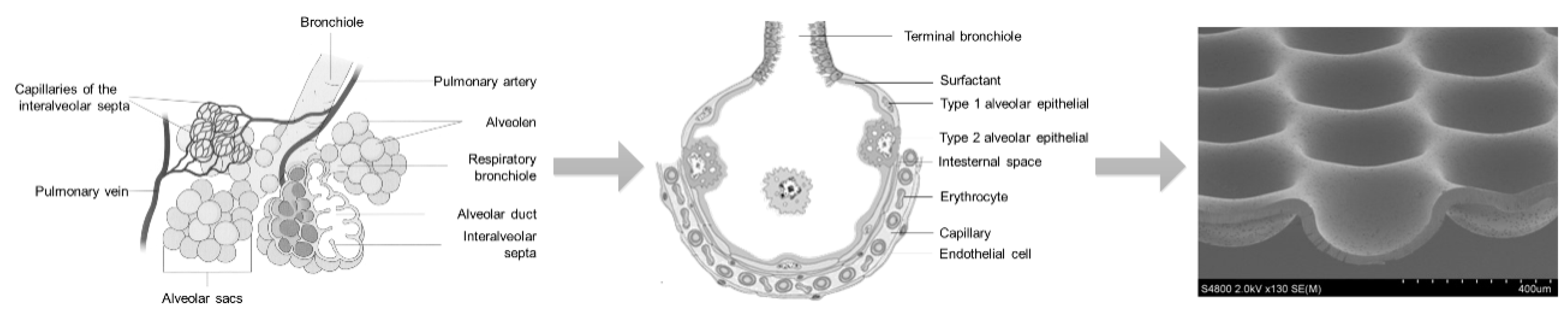
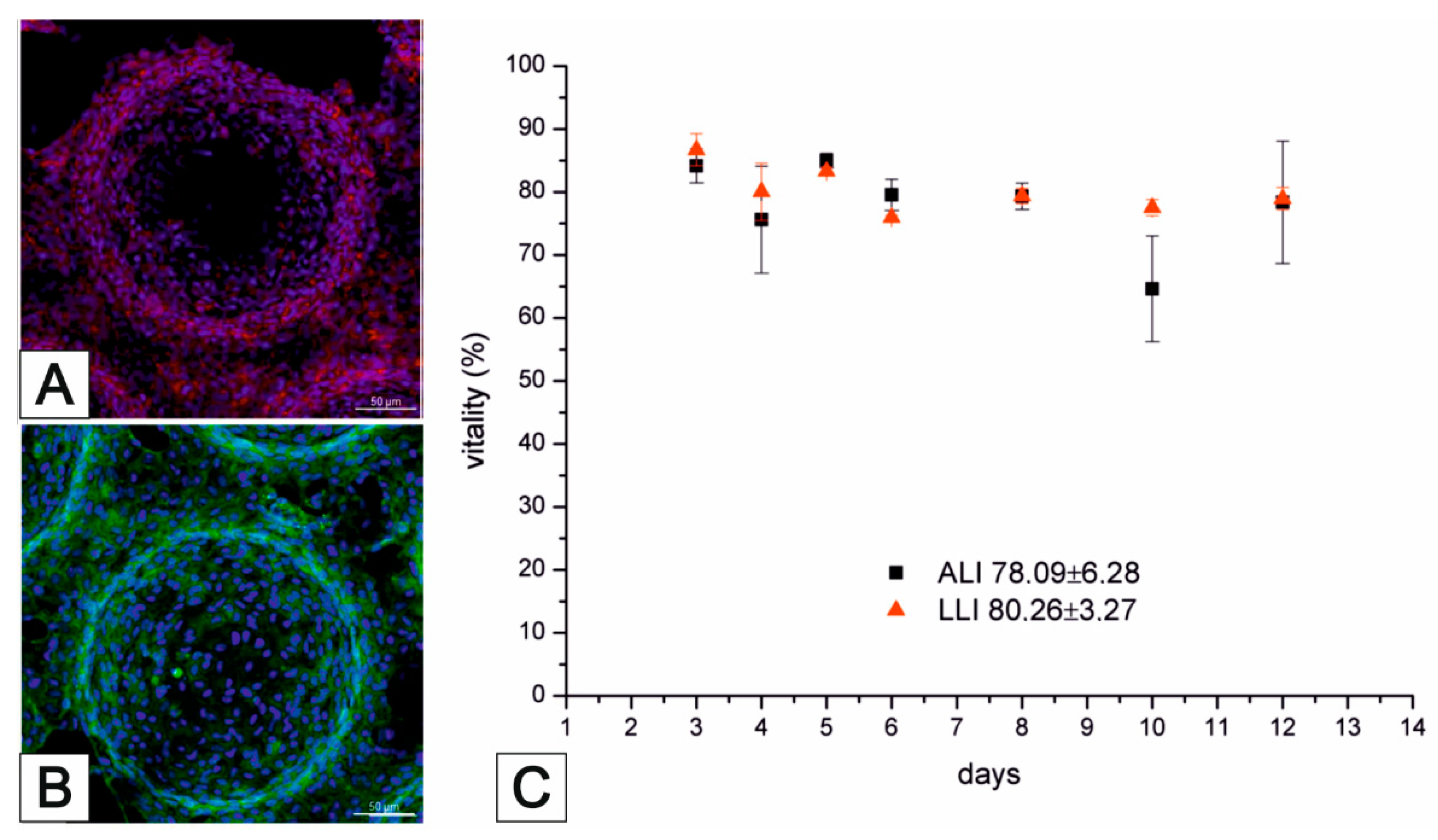
3.2. Lung MatriGrid®—An Example of Directed Oligocellular Coculture

Early cell culture models of the lung were mostly based on flat and porous membranes made of, e.g., polycarbonate (PC) or polyethylene terephthalate (PET), on which different combinations of alveolar cells, epithelial cells, and blood cells were cultured [47][48][49][50]. Khalid et al. have developed a lung-cancer-on-chip platform as a promising tool for the cytotoxicity evaluation of novel drug compounds [51].
While using well plate inserts in an air–liquid-interface could be applied to these models to mimic specific lung physiology, Huh et al. [52] were the first to report a lung-on-chip model with a uniaxially stretched membrane to mimic the breathing motion of the lung. In a similar approach, Huang et al. reported a hydrogel-based physiologically relevant model of human pulmonary alveoli [53]. That concept was later improved with a 3D-stained PDMS membrane [54] and the integration of impedance sensors to monitor cell behavior and membrane movement [55]. Furthermore, with respect to the alveoli dimensions, a biodegradable and stretchable biological membrane from collagen and elastin was reported to mimic the central aspects of the air–blood barrier [56]. Comparative to that approach within the MatriGrid®-family, a Lung-MatriGrid® based on the shape and size of human lung alveoli was developed using the previously described biotechnical microscale engineering and micro thermoforming technology (Figure 5).
Figure 5. Biotechnical multiscale engineering of the lung.
The Lung-MatriGrid® permits the possibility of a 3D oligocellular coculture model of the blood–air barrier with respect to physiological characteristics. The blood–air barrier is characterized by an extremely thin and highly connected layer of epithelial cells that is spread over pulmonary capillaries [57]. Only a 1–2 µm thin structure supports the passive diffusion of respiratory gases [58]. To enable such organotypic exposure of the alveolar epithelia cells against ambient air, the oligocellular coculture model is cultured under an air–liquid interface (ALI) condition. This more physiological ALI culturing is realized by attaching the Lung-MatriGrid® onto the previously described semi-active system (Figure 5). The barrier itself is realized by the seeding of capillary endothelia cells to the basal side of the scaffold, while alveolar epithelia cells are brought into the alveolar-like cavities on the apical side (Figure 6)
Figure 6. (A) Scheme of generation of 3D co-culture. Seeding of endothelial cells on the basal side of the MatriGrid®s in a petri dish, transfer to an MTP, and seeding of the apical side with epithelial cells, 24 h incubation as LLI Culture, creation of the ALI culture; (B) MatriGrid®, (C) REM-picture of a sliced MatriGrid®, dimensions of the cavities (red arrows), (D) semi-active system with MatriGrid® on the bottom, (E) 24-well MTP assembled with semi-active systems.
The medium in ALI culturing is only present underneath the basal side of the scaffold supply of the apical cells, which is ensured by the porosity of the scaffold (pore diameter = 2–4 µm, pore density = 106 pores/cm2, thickness = 10–40 µm). Viability and metabolic activity of alveolar epithelial cells (A549) and capillary endothelia cells (EAhy.926) cultured in a lung MatriGrid® are shown to be not compromised in comparison to the culturing in a liquid–liquid interface (LLI) culture over 12 days (Figure 7). Additionally, A549 forms a thick monolayer, with the expression of cell-adhesion molecules (ZO-1, E-cadherin) in the cavities of the Lung-MatriGrid® (Figure 6A). Since the Lung-MatriGrid® can be reversibly separated from the insert system, the cell layer on the scaffold, as well as the cell culture medium, can be evaluated with established methods such as (immuno)-histochemical staining or ELISA to identify changes in cytokine levels or the expression of cell-adhesion molecules due to exposure to, e.g., nanoparticles. Further research is ongoing in the DFG project (DFG 397981139) in cooperation with the Institute of Environmental Toxicology at Martin-Luther-University Halle-Wittenberg to examine the toxicity of BaSO4 nanoparticles on primary cells and cell lines in Lung-MatriGrid®s.
Figure 7. Immunohistochemical stainings of cell-adhesion molecules. (A) Zonula occludens-1 and (B) E-cadherin; (C) comparison of the viability of air–liquid interface (ALI) and liquid–liquid interface (LLI) cultures of A549 on the apical side of the MatriGrid®. Bar represents 50 µm.

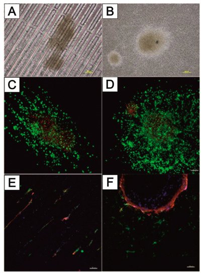
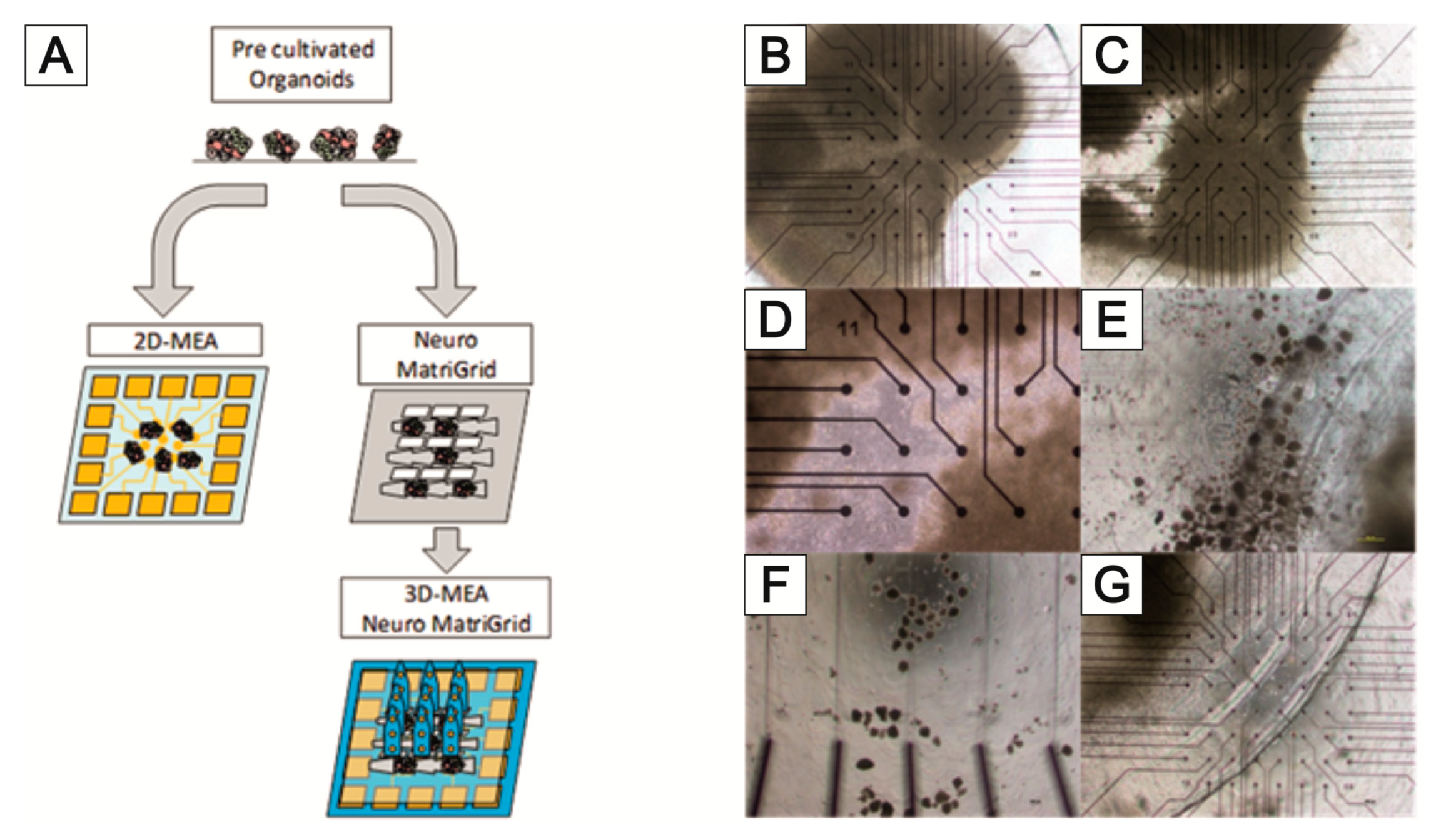
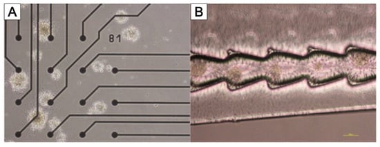
3.3. NeuroGrid®—Scaffolds for the Manipulation and Directed Growth of Neurons and Cerebral Organoids

It is well known that different cellular processes, such as attachment, proliferation, directional migration, and differentiation of neurons, are dependent on morphological and biochemical cues in the surrounding surface [59][60][61]. In this way, the direction and outgrowth of axons and dendrites have been studied by symmetric or asymmetric shapes of trenches [62][63] or specific microplates [64] to guide the connectivity between 3D neuronal cell clusters [65] or to record muscle activity after stimulation of axons in different microfluidic chambers [66]. In addition, there are indications found that the migration capacity of neural cells depends on the stage of neuronal differentiation [67]. Additionally, circular 3D PDMS scaffolds have been used for defining spheroid-like neuronal cell agglomerates [68]. The design of polymeric scaffolds in PC was described in here, which should be used as a proof-of-concept study for the handling and shaping of neurons and neuronal organoids.
For this reason, it is being investigated whether appropriate modifications of the MatriGrid® scaffold can enable the directed growth of neurons to reproduce desired morphologies, with the vision of developing flexible tools to mimic the complex hierarchies of neuronal tissue. Various designs of MatriGrid®s were used to induce the guided growth of embryonic and adult neurons. The set of MatriGrid®s with function-dependent embossed structures is given in Figure 8. Besides the fact that neurons are guided easily by microchannels, the geometries of structures were inspired by the size of neuronal fiber bundles, which are in the range of approximately 500 µm in the case of a cortical column [69][70].
Figure 8. Scaffold designs for guided cell growth; (A) vertical and horizontal trenches; (B,C) different scaled tree structures to mimic the cortical column; (D) NeuroGrid® tool with openings for the 3D MEA.
Primary rat cortical neurons were used to allow directed growth through the structures. In the same way, the culturing of neurospheres from induced pluripotent stem cells (iPSC) was investigated. MatriGrid® cultures are also used to bring the guided neurons into close contact with microelectrodes of 2D and 3D MEAs so that it is easier to capture the neuronal signals. That targeted application of MatriGrid® scaffolds can easily be extended by stacking those scaffolds to create complex 3D models to evaluate real 3D network signals from neuronal cells.
Figure 9 shows the directional growth of neuronal cells that have grown out of neurospheres. The typical radial outgrowth of neuronal cells from a neurosphere can be seen on the unstructured PC foil (Figure 9B), although it is not possible to evaluate the growth of neurons within the trench structure using bright field microscopy (Figure 9A). Cell staining is needed to estimate any guided neuronal cell growth inside the narrow NeuroGrid®-structures. Live–dead staining as well as immunofluorescence staining against neuronal markers microtubulin-associated protein 2 (MAP2) and βIII-tubulin (TUBB3) were performed. In addition, the cell nuclei were stained with DAPI (blue). The trench structure forces a directional growth compared to the unstructured PC foil (Figure 9C,D). Mainly viable (green-stained) cells outside the neurospheres can be seen. Viable cells, on the other hand, are present in the neurospheres. While TUBB3-stained neurons grow along the trenches, MAP2-stained cells do not undergo this directed growth and are also found in the areas between the trenches (Figure 9E). In contrast, on the unstructured PC foil, mainly MAP2-stained cells grow out of the aggregates of the rat cortex neurons, and only a small number of TUBB3-stained cells can be seen (Figure 9F).
Figure 9. Directional growth of neuronal cells within tranches and radial growth on unstructured PC foil. Brightfield microscopy of the (A) channel structure and (B) unstructured PC foil. Live–dead staining of neurospheres on the (C) channel structure and (D) unstructured PC foil (green—viable cells, red—dead cells). Immunofluorescence staining of rat cortex neurons within (E) a trench structure and (F) on unstructured PC foil (blue—cell nuclei (DAPI), red—βIII-tubulin (TUBB3, Alexa Fluor 594), green—microtubulin-associated protein 2 (MAP2, Alexa Fluor 488)). Bar represents 100 µm.
A major problem in deriving neuronal signals is the growth of neuronal cells outside the sensor area of the MEA. This circumstance makes planning more difficult and prevents the standardization of the experiments. For this reason, the targeted application of neuronal cells to the electrodes of the 2D and 3D MEAs was tested using MatriGrid® foils (Figure 10A). Normal PC foils and MatriGrid® with a towering tree structure were used for the experiments with 2D MEAs. Special 3D MEA foils with cutouts for the 3D needle electrodes were used for targeted positioning on 3D MEAs. In both variants, neurospheres were pre-cultured on the foils for 7 days and then transferred to the 2D or 3D MEA and cultured further for at least 7 days. The signals were recorded daily after the transfer to the MEA. The neurospheres for the 2D MEA were pipetted as centrally as possible onto the foil or into the tree structures of the MatriGrid®. For the 3D MEA, neurospheres were placed in the structures on the ridges between the cutouts for the needle electrodes. All foils were coated with Geltrex in order to cover the entire foil with cells. Figure 10 shows the behavior of the neuronal cells after application over a culturing period of 9 days. While the neurospheres are intact on the first day after the transfer (Figure 10B), they show gaps during longer culturing, which become larger the longer the foils are cultured on the MEAs (Figure 10C,D). Individual outgrown neuronal cells can be seen within these gaps. However, it cannot be seen whether these have grown on the foil or the MEA (Figure 10D). After a few days, detached cells are present in the medium, both at the edge of the foils placed (Figure 10E) and over the remaining MEA surface (Figure 10F). These do not adhere to the surface of the MEA but form cell aggregates. It could also be observed that the PC film slips on the 2D MEA when changing the medium (Figure 10F).
Figure 10. (A) Principles of targeted application of neuronal cells by MatriGrid®; (B) neurospheres transferred from MatriGrid® to 2D MEA after 1 day; (C) 6 days and (D) 9 days of culturing; detached neuronal cells (E) at the edge of the applied foil and (F) on the outer MEA surface; (G) PC film slipped after medium change.
Figure 11 shows the 3D MEA foil before it was transferred to the 3D MEA (Figure 11A). When the foil was applied, it was transferred to the 3D MEA with the cells facing down. When neurospheres are cultured in the tree structures of the 3D MEA foil, they can be placed directly on the needle electrodes (Figure 11B); when cultured on the ridges between the cutouts, it is also possible to position the neurospheres specifically on the bottom electrodes of the 3D MEA (Figure 11C). It should be noted that individual neurospheres can become detached from the 3D MEA film during transfer (comparison of Figure 11A,B).
Figure 11. The 3D MEA foil for the targeted application of neurospheres on MEA electrodes. (A) Bright-field image of the 3D MEA foil before transfer to the 3D MEA; (B) 3D MEA without 3D MEA foil; (C) 3D MEA with 3D MEA foil and spheroid with contact with the needle electrodes; (D) sketch of a 3D MEA with bioreactor housing and 3D-stacked NeuroGrids; bar represents 500 µm.
Figure 12 shows an example of a 3D MEA measurement of neuronal signals after the targeted application of a 3D MEA foil. Neural signals were measured at the opposing electrodes B-014 and B-020 (comparison of Figure 12A,B). Here, electrode B-020 is a bottom electrode that is opposite the middle needle electrode B-014. The signals from the two electrodes show a high degree of synchronicity (Figure 12C). The background noise of the electrodes is between 5 and 10 µV; mainly negative spikes with a maximum of 20 µV were measured. Both signals contained bursts.
Figure 12. Neuronal signals measured after transferring the 3D MEA film to a 3D MEA (7 days of pre-culturing in a 6-well MTP and 7 days of culturing on the MEA) (A) Electrode array with numbering of the electrodes (B) Measurement from middle of the needle electrode (B-014) (C) Measurement on bottom electrode (B-020).
Besides the use for the directed growth of neurons and a targeted application to 2D or 3D MEAs, the MatriGrid®s can also be used as a handling tool to create more uniform spheroids of neuronal cells. For this purpose, dissociated rat cortex neurons were pipetted into the cavities of the MatriGrid®s. The cavities were previously coated with anti-adherence rinsing solutions. The spheroids precultured and shaped in the MatriGrid® were transferred directly onto 2D MEAs or into structures of other MatriGrid®s (Figure 13). For both approaches, the attachment of the spheroids and the outgrowth of neurons were verifiable. A big advantage of that approach in forming spheroids is the possibility of defining the diameter of the spheroid through the size of the cavities. Because of that, the spheroids are highly adaptable to the purpose they will be used for.
Figure 13. (A) Spheroids generated from cortex neurons in MatriGrid® adhered to 2D MEAs and (B) in the fir-tree structures of the 3D MEA foil. Bar represents 100 µm.

3.4. TissGrid®

The need for adapted scaffold structures is not only important in cell cultures based on cell lines or primary cell cultures; the culturing of explants or tissue slices can also benefit from the advantages of a scaffold approach. The scaffold creates an adapted microenvironment for the specific explant and, thus, optimal survival conditions. This is particularly important for longer culturing periods. Flow-induced shear stress has a big influence on cells and tissues [71][72][73][74][75], either in a positive way, mimicking the effects of vascularization, or in a negative way on sensitive cells and tissue slices, where the stress damages the cells. In a case study, this effect on placenta tissues has been examined, called placenta explants, because drug and particle transport across the human placenta is a deciding factor for fetus development [76][77]. It is generally known that fluidics also have a major influence on the cellular phenotypes of the placenta [78]. Therefore, it is desirable not only to culture the explants statically but also to culture them inside microfluidic systems. Placenta explants are sensitive tissue structures that lose their integrity under fluid shear stress; they cannot maintain their viability for an indefinite period. The fluid stress effects on explants under different fluidic regimes was examined. Following the observation that placenta explants are very sensitive, a new scaffold structure was designed, which combined the potential shelter function of a porous cavity with the advantage of better fluidic supply with respect to nutritious flow. The TissGrid® structure is designed in the following way. A central cylindrical cavity standing on a porous base surface is used to accommodate the explant. This can be easily inserted into the scaffold from above without damage. The cavity is made of microporous transparent polycarbonate film by thermoforming. Microscopic observation of the explant is possible during culturing. Due to the porosity, a very good diffusive supply of cells is possible. In order to achieve an effective flow around the explant cylinder and, thus, high diffusion gradients, bypass openings were inserted at the corners of the base surface. The base surface was also made of porous polycarbonate film, which also allows the microscopic inspection of the samples. To integrate the system into the microreactors described above, the scaffolds were fixed onto a carrier chip. In order to avoid an undesired influence on cell culture, no adhesives should be used to bind the scaffolds. Especially in long-term cultures, substances may leach out of the adhesive. In the application described here, the scaffold parts were, therefore, bonded with solvent. This could be completely removed by appropriate heat treatment in a vacuum. This way, easy storage and handling and good sealing of the scaffold in the bioreactor are possible. A schematic representation of the TissGrid® is shown in Figure 14.
Figure 14. (A) Schematic of TissGrid® with the flow path of the fluid; (B) the manufactured TissGrid®.
It was able to show that with the specially designed TissGrid®s, a flow-through protective structure could be set up, which enables the explants to be supplied with medium/serum flowing past while maintaining viability [79].
Under conventional culture conditions, without the influence of test substances, it was able to observe relatively stable glucose consumption and stable lactate production in placenta explants in a conventional microtiter plate (MTP) for up to 10 days, which indicates good placental functionality and metabolism. By changing the culture conditions with the help of specially developed fluidic systems (TissGrid®s in bioreactors [79]Figure 15), a placental-active metabolism could even be stimulated, which shows an increased production of estradiol by the syncytiotrophoblast at flow rates of 100 µL/min of the culture medium (unpublished data). The substrate structures were thoroughly tested and led to the specially developed TissGrid®. In addition, different flow rates were varied in these experiments.
Figure 15. Live–dead assays to determine the viability of placental explants after 14 days of culture under fluidic conditions are shown to the left of the TissGrid® (B) and the MatriGrid® (D). Viable tissue is green; dead tissue is red. The villous structures of the placenta react very sensitively to shearing forces, which leads to a significant reduction in the viability of the placental tissue in the MatriGrid® (C). The protected environment in the TissGrid®, on the other hand, enables excellent regeneration of the placenta explant (A). In the live–dead assay, the original degenerated syncytiotrophoblast (red) can be seen, which has been replaced by a newly formed one (green) on the surface of the explant (A).
In contrast, the relative decrease in estradiol production under static (not perfused) conditions (2D, static plate) and the low flow rates of 10 µL/min indicate the degeneration and decreased function of the explants. Preliminary tests also showed that it was not possible to carry out tests at high flow rates in the structures developed for 3D cell culture (called MatriGrid®s (Figure 15)). The tissue lost its intact structure (Figure 15C). With the help of the TissGrid®s in special MTPs or microbioreactors designed for this purpose (Figure 15A), which are to be standardized, a further time window can be opened up due to the supply of the placenta explants with culture medium.
Besides the culturing of primary cells and even explants in fluidic setups, as described before, long-term experiments bear a high potential for the application of MatriGrid® scaffolds.

References

  1. Joseph, J.; Sundar, R.; John, A.; Abraham, A. Phytochemical Incorporated Drug Delivery Scaffolds for Tissue Regeneration. Regen. Eng. Transl. Med. 2018, 4, 167–176.
  2. Bialkowska, K.; Komorowski, P.; Bryszewska, M.; Milowska, K. Spheroids as a Type of Three-Dimensional Cell Cultures-Examples of Methods of Preparation and the Most Important Application. Int. J. Mol. Sci. 2020, 21, 6225.
  3. Breslin, S.; O’Driscoll, L. Three-dimensional cell culture: The missing link in drug discovery. Drug Discov. Today 2013, 18, 240–249.
  4. Lancaster, M.A.; Knoblich, J.A. Generation of cerebral organoids from human pluripotent stem cells. Nat. Protoc. 2014, 9, 2329–2340.
  5. Langer, R.; Tirrell, D.A. Designing materials for biology and medicine. Nature 2004, 428, 487–492.
  6. Chitcholtan, K.; Asselin, E.; Parent, S.; Sykes, P.H.; Evans, J.J. Differences in growth properties of endometrial cancer in three dimensional (3D) culture and 2D cell monolayer. Exp. Cell Res. 2013, 319, 75–87.
  7. Bier, W.; Dertinger, H.; Knedlitschek, G.; Schaller, T.; Schubert, K.; Weibezahn, K.F. Substrat Für Zellkulturen und Kultur Von Zellen Oder Zellaggregaten. Patent DE000004132379A1, 8 April 1993.
  8. Doering, M.; Eigen, M.; Guenther, R.; Henco, K.; Koehler, M.; Schober, A.; Schweinhorst, A.; Thuerk, M. Probentraeger und Seine Verwendung. Patent WO001995001559A3, 1995.
  9. Giselbrecht, S.; Gietzelt, T.; Gottwald, E.; Trautmann, C.; Truckenmuller, R.; Weibezahn, K.F.; Welle, A. 3D tissue culture substrates produced by microthermoforming of pre-processed polymer films. Biomed. Microdevices 2006, 8, 191–199.
  10. Schober, A.; Fernekorn, U.; Singh, S.; Schlingloff, G.; Gebinoga, M.; Hampl, J.; Williamson, A. Mimicking the biological world: Methods for the 3D structuring of artificial cellular environments. Eng. Life Sci. 2013, 13, 352–367.
  11. Schober, A.; Hampl, J. Mikrostrukturierter Formkörper Mit Perforierten Teilen und Verfahren Zu Dessen Herstellung. Patent EP 2,403,630, 27 September 2009.
  12. Borowiec, J.; Hampl, J.; Gebinoga, M.; Elsarnagawy, T.; Elnakady, Y.A.; Fouad, H.; Almajhadi, F.; Fernekorn, U.; Weise, F.; Singh, S.; et al. Thermoforming techniques for manufacturing porous scaffolds for application in 3D cell cultivation. Mater. Sci. Eng. C Mater. Biol. Appl. 2015, 49, 509–516.
  13. Fernekorn, U.; Hampl, J.; Augspurger, C.; Hildmann, C.; Weise, F.; Klett, M.; Laffert, A.; Gebinoga, M.; Williamson, A.; Schober, A. In vitro cultivation of biopsy derived primary hepatocytes leads to a more metabolic genotype in perfused 3D scaffolds than static 3D cell culture. RSC Adv. 2013, 3, 16558–16568.
  14. Bingel, C.; Koeneke, E.; Ridinger, J.; Bittmann, A.; Sill, M.; Peterziel, H.; Wrobel, J.; Rettig, I.; Milde, T.; Fernekorn, U.; et al. Three-dimensional tumor cell growth stimulates autophagic flux and recapitulates chemotherapy resistance. Cell Death Dis. 2017, 8, e3013.
  15. Zeussel, L.; Hampl, J.; Weise, F.; Singh, S.; Schober, A. Bio-inspired 3D micro structuring of a liver lobule via direct laser writing: A comparative study with SU-8 and SUEX. J. Laser Appl. 2022, 34, 012007.
  16. Mai, P.; Fernekorn, U.; Hampl, J.; Schober, A.; Foth, H. Deutsche Gesellschaft für Experimentelle und Klinische Pharmakologie und Toxikologie e.V. Naunyn-Schmiedeberg’s Arch. Pharmacol. 2014, 387, 1–113.
  17. Schneider, D.; Schumann, B.; Glahn, F.; Krings, O.; Tomisch, L.; Thomas, S.; Bacanli, M.; Mai, P.; Schober, A.; Foth, H. Establishment of a lung cell Co-culture model for nanoparticle aerosol exposition. Naunyn-Schmiedeberg’s Arch. Pharmacol. 2020, 393, 56.
  18. Marx-Blümel, L.; Marx, C.; Weise, F.; Frey, J.; Perner, B.; Schlingloff, G.; Lindig, N.; Hampl, J.; Sonnemann, J.; Brauer, D.; et al. Biomimetic reconstruction of the hematopoietic stem cell niche for in vitro amplification of human hematopoietic stem cells. PLoS ONE 2020, 15, e0234638.
  19. Marx-Blümel, L.; Marx, C.; Sonnemann, J.; Weise, F.; Hampl, J.; Frey, J.; Rothenburger, L.; Cirri, E.; Rahnis, N.; Koch, P.; et al. Molecular characterization of hematopoietic stem cells after in vitro amplification on biomimetic 3D PDMS cell culture scaffolds. Sci. Rep. 2021, 11, 21163.
  20. Schober, A.; Hampl, J.; Weise, F.; Borowiec, J.; Fernekorn, U.; Gebinoga, M.; Singh, S.; Schlingloff, G.; Häfner, S.; Beck, J.; et al. Reproduction of a Stem Cell Niche of an Organism and Method for the Generation Thereof. U.S. Patent 10,780,613, 22 September 2020.
  21. Borowiec, J.W. Fabrication and characterization of microstructured scaffolds for complex 3D cell cultures. Ilmenau 2022.
  22. Schober, A.; Hampl, J.; Weise, F. Mikrostrukturierter Formkoerper mit perforierten Teilen und Verfahren zu dessen Herstellung. Patent WO2011035938A1, 31 March 2011.
  23. Worgull, M. Hot Embossing. In Micromanufacturing Engineering and Technology; William Andrew Publishing: Boston, MA, USA, 2009; pp. 68–89.
  24. Sekhon, G.S.; Kumar, S.; Kaur, C.; Verma, N.K.; Chakarvarti, S.K. Effect of thermal annealing on pore density, pore size and pore homogeneity of polycarbonate NTFs. Radiat. Meas. 2008, 43, 1357–1359.
  25. Martinez-Rivas, A.; González-Quijano, G.K.; Proa-Coronado, S.; Séverac, C.; Dague, E. Methods of Micropatterning and Manipulation of Cells for Biomedical Applications. Micromachines 2017, 8, 347.
  26. Waterkotte, B.; Bally, F.; Nikolov, P.; Waldbaur, A.; Rapp, B.; Truckenmüller, R.; Lahann, J.; Schmitz, K.; Giselbrecht, S. Biofunctional Micropatterning of Thermoformed 3D Substrates. Adv. Funct. Mater. 2014, 24, 442–450.
  27. Sun, Y.; Jallerat, Q.; Szymanski, J.M.; Feinberg, A.W. Conformal nanopatterning of extracellular matrix proteins onto topographically complex surfaces. Nat. Methods 2015, 12, 134–136.
  28. Moraes, C.; Kim, B.C.; Zhu, X.; Mills, K.L.; Dixon, A.R.; Thouless, M.D.; Takayama, S. Defined topologically-complex protein matrices to manipulate cell shape via three-dimensional fiber-like patterns. Lab Chip 2014, 14, 2191–2201.
  29. Borowiec, J.; Hampl, J.; Singh, S.; Haefner, S.; Friedel, K.; Mai, P.; Brauer, D.; Ruther, F.; Liverani, L.; Boccaccini, A.; et al. 3D Microcontact Printing for Combined Chemical and Topographical Patterning on Porous Cell Culture Membrane. ACS Appl. Mater. Interfaces 2018, 10, 22857–22865.
  30. Kaufmann, T.; Ravoo, B.J. Stamps, inks and substrates: Polymers in microcontact printing. Polym. Chem. 2010, 1, 371–387.
  31. Truckenmüller, R.; Giselbrecht, S.; Rivron, N.; Gottwald, E.; Saile, V.; Van den Berg, A.; Wessling, M.; Van Blitterswijk, C. Thermoforming of film-based biomedical microdevices. Adv. Mater. 2011, 23, 1311–1329.
  32. Tobola, J.; Gebinoga, M.; Hampl, J.; Elsarnagawy, T.; Elnakady, Y.A.; Fouad, H.; Almajhadi, F.; Fernekorn, U.; Weise, F.; Klett, M.; et al. 3D polylactide scaffolds and polylactic -polycarbonate composite scaffolds manufactured through thermoforming for application in advanced cell culture. BioNanoMaterials 2012, 13, 27–35.
  33. Lee, S.J.; San Choi, J.; Park, K.S.; Khang, G.; Lee, Y.M.; Lee, H.B. Response of MG63 osteoblast-like cells onto polycarbonate membrane surfaces with different micropore sizes. Biomaterials 2004, 25, 4699–4707.
  34. Singh, S.; Lei, Y.; Schober, A. Direct extraction of carbonyl from waste polycarbonate with amines under environmentally friendly conditions: Scope of waste polycarbonate as a carbonylating agent in organic synthesis. RSC Adv. 2015, 5, 3454–3460.
  35. Singh, S.; Friedel, K.; Himmerlich, M.; Lei, Y.; Schlingloff, G.; Schober, A. Spatiotemporal Photopatterning on Polycarbonate Surface through Visible Light Responsive Polymer Bound DASA Compounds. ACS Macro Lett. 2015, 4, 1273–1277.
  36. Singh, S.; Mai, P.; Borowiec, J.; Zhang, Y.; Lei, Y.; Schober, A. Donor-acceptor Stenhouse adduct-grafted polycarbonate surfaces: Selectivity of the reaction for secondary amine on surface. R. Soc. Open Sci. 2018, 5, 180207.
  37. Lee, H.; Chae, S.; Kim, J.Y.; Han, W.; Kim, J.; Choi, Y.; Cho, D.-W. Cell-printed 3D liver-on-a-chip possessing a liver microenvironment and biliary system. Biofabrication 2019, 11, 025001.
  38. Wang, Y.; Wang, H.; Deng, P.; Chen, W.; Guo, Y.; Tao, T.; Qin, J. In situ differentiation and generation of functional liver organoids from human iPSCs in a 3D perfusable chip system. Lab Chip 2018, 18, 3606–3616.
  39. Shah, U.-K.; Mallia, J.d.O.; Singh, N.; Chapman, K.E.; Doak, S.H.; Jenkins, G.J.S. A three-dimensional in vitro HepG2 cells liver spheroid model for genotoxicity studies. Mutat. Res. Genet. Toxicol. Environ. Mutagenesis 2018, 825, 51–58.
  40. Gomez-Lechon, M.J.; Tolosa, L.; Conde, I.; Donato, M.T. Competency of different cell models to predict human hepatotoxic drugs. Expert Opin. Drug Metab. Toxicol. 2014, 10, 1553–1568.
  41. Levy, G.; Bomze, D.; Heinz, S.; Ramachandran, S.D.; Noerenberg, A.; Cohen, M.; Shibolet, O.; Sklan, E.; Braspenning, J.; Nahmias, Y. Long-term culture and expansion of primary human hepatocytes. Nat. Biotechnol. 2015, 33, 1264–1271.
  42. Noerenberg, A.; Heinz, S.; Scheller, K.; Hewitt, N.; Braspenning, J.; Ott, M. Optimization of upcyte (R) human hepatocytes for the in vitro micronucleus assay. Mutat. Res. 2013, 758, 69–79.
  43. Tolosa, L.; Gomez-Lechon, M.J.; Lopez, S.; Guzman, C.; Castell, J.V.; Donato, M.T.; Jover, R. Human Upcyte Hepatocytes: Characterization of the Hepatic Phenotype and Evaluation for Acute and Long-Term Hepatotoxicity Routine Testing. Toxicol. Sci. 2016, 152, 214–229.
  44. Burkard, A.; Dähn, C.; Heinz, S.; Zutavern, A.; Sonntag-Buck, V.; Maltman, D.; Przyborski, S.; Hewitt, N.J.; Braspenning, J. Generation of proliferating human hepatocytes using Upcyte® technology: Characterisation and applications in induction and cytotoxicity assays. Xenobiotica 2012, 42, 939–956.
  45. Broeders, J.J.; Parmentier, C.; Truisi, G.L.; Josse, R.; Alexandre, E.; Savary, C.C.; Hewitt, P.G.; Mueller, S.O.; Guillouzo, A.; Richert, L.; et al. Biokinetics of chlorpromazine in primary rat and human hepatocytes and human HepaRG cells after repeated exposure. Toxicol. Vitr. 2015, 30, 52–61.
  46. Mueller, D.; Kramer, L.; Hoffmann, E.; Klein, S.; Noor, F. 3D organotypic HepaRG cultures as in vitro model for acute and repeated dose toxicity studies. Toxicol. Vitr. 2014, 28, 104–112.
  47. Alfaro-Moreno, E.; Nawrot, T.S.; Vanaudenaerde, B.M.; Hoylaerts, M.F.; Vanoirbeek, J.A.; Nemery, B.; Hoet, P.H. Co-cultures of multiple cell types mimic pulmonary cell communication in response to urban PM10. Eur. Respir. J. 2008, 32, 1184–1194.
  48. Hermanns, M.I.; Fuchs, S.; Bock, M.; Wenzel, K.; Mayer, E.; Kehe, K.; Bittinger, F.; Kirkpatrick, C.J. Primary human coculture model of alveolo-capillary unit to study mechanisms of injury to peripheral lung. Cell Tissue Res. 2009, 336, 91–105.
  49. Klein, S.G.; Serchi, T.; Hoffmann, L.; Blomeke, B.; Gutleb, A.C. An improved 3D tetraculture system mimicking the cellular organisation at the alveolar barrier to study the potential toxic effects of particles on the lung. Part. Fibre Toxicol. 2013, 10, 31.
  50. Rothen-Rutishauser, B.M.; Kiama, S.G.; Gehr, P. A three-dimensional cellular model of the human respiratory tract to study the interaction with particles. Am. J. Respir. Cell Mol. Biol. 2005, 32, 281–289.
  51. Khalid, M.A.U.; Kim, Y.S.; Ali, M.; Lee, B.G.; Cho, Y.-J.; Choi, K.H. A lung cancer-on-chip platform with integrated biosensors for physiological monitoring and toxicity assessment. Biochem. Eng. J. 2020, 155, 107469.
  52. Huh, D.; Matthews, B.D.; Mammoto, A.; Montoya-Zavala, M.; Hsin, H.Y.; Ingber, D.E. Reconstituting Organ-Level Lung Functions on a Chip. Science 2010, 328, 1662–1668.
  53. Huang, D.; Liu, T.; Liao, J.; Maharjan, S.; Xie, X.; Pérez, M.; Anaya, I.; Wang, S.; Tirado Mayer, A.; Kang, Z.; et al. Reversed-engineered human alveolar lung-on-a-chip model. Proc. Natl. Acad. Sci. USA 2021, 118, e2016146118.
  54. Stucki, A.O.; Stucki, J.D.; Hall, S.R.; Felder, M.; Mermoud, Y.; Schmid, R.A.; Geiser, T.; Guenat, O.T. A lung-on-a-chip array with an integrated bio-inspired respiration mechanism. Lab Chip 2015, 15, 1302–1310.
  55. Mermoud, Y.; Felder, M.; Stucki, J.D.; Stucki, A.O.; Guenat, O.T. Microimpedance tomography system to monitor cell activity and membrane movements in a breathing lung-on-chip. Sens. Actuators B Chem. 2018, 255, 3647–3653.
  56. Zamprogno, P.; Wuthrich, S.; Achenbach, S.; Thoma, G.; Stucki, J.D.; Hobi, N.; Schneider-Daum, N.; Lehr, C.M.; Huwer, H.; Geiser, T.; et al. Second-generation lung-on-a-chip with an array of stretchable alveoli made with a biological membrane. Commun. Biol. 2021, 4, 168.
  57. Hoppin, J.A.; Umbach, D.M.; London, S.J.; Lynch, C.F.; Alavanja, M.C.R.; Sandler, D.P. Pesticides and adult respiratory outcomes in the agricultural health study. Ann. N. Y. Acad. Sci. 2006, 1076, 343–354.
  58. Gehr, P.; Bachofen, M.; Weibel, E.R. Normal Human Lung-Ultrastructure and Morphometric Estimation of Diffusion Capacity. Resp. Physiol. 1978, 32, 121–140.
  59. Farrukh, A.; Zhao, S.F.; del Campo, A. Microenvironments Designed to Support Growth and Function of Neuronal Cells. Front. Mater. 2018, 5, 62.
  60. Li, N.; Folch, A. Integration of topographical and biochemical cues by axons during growth on microfabricated 3-D substrates. Exp. Cell Res. 2005, 311, 307–316.
  61. Simitzi, C.; Ranella, A.; Stratakis, E. Controlling the morphology and outgrowth of nerve and neuroglial cells: The effect of surface topography. Acta Biomater. 2017, 51, 21–52.
  62. Ristola, M.; Fedele, C.; Hagman, S.; Sukki, L.; Kapucu, F.E.; Mzezewa, R.; Hyvarinen, T.; Kallio, P.; Priimagi, A.; Narkilahti, S. Directional Growth of Human Neuronal Axons in a Microfluidic Device with Nanotopography on Azobenzene-Based Material. Adv. Mater. Interfaces 2021, 8, 2100048.
  63. Gladkov, A.; Pigareva, Y.; Kutyina, D.; Kolpakov, V.; Bukatin, A.; Mukhina, I.; Kazantsev, V.; Pimashkin, A. Design of Cultured Neuron Networks in vitro with Predefined Connectivity Using Asymmetric Microfluidic Channels. Sci. Rep. 2017, 7, 15625.
  64. Yoshida, S.; Kato-Negishi, M.; Takeuchi, S. Assembly and Connection of Micropatterned Single Neurons for Neuronal Network Formation. Micromachines 2018, 9, 235.
  65. Ming, Y.; Abedin, M.J.; Tatic-Lucic, S.; Berdichevsky, Y. Microdevice for directional axodendritic connectivity between micro 3D neuronal cultures. Microsyst. Nanoeng. 2021, 7, 67.
  66. Duc, P.; Vignes, M.; Hugon, G.; Sebban, A.; Carnac, G.; Malyshev, E.; Charlot, B.; Rage, F. Human neuromuscular junction on micro-structured microfluidic devices implemented with a custom micro electrode array (MEA). Lab Chip 2021, 21, 4223–4236.
  67. Lee, N.; Park, J.W.; Kim, H.J.; Yeon, J.H.; Kwon, J.; Ko, J.J.; Oh, S.H.; Kim, H.S.; Kim, A.; Han, B.S.; et al. Monitoring the differentiation and migration patterns of neural cells derived from human embryonic stem cells using a microfluidic culture system. Mol. Cells 2014, 37, 497–502.
  68. Hasan, M.F.; Ghiasvand, S.; Wang, H.; Miwa, J.M.; Berdichevsky, Y. Neural layer self-assembly in geometrically confined rat and human 3D cultures. Biofabrication 2019, 11, 045011.
  69. Roe, A.W. Columnar connectome: Toward a mathematics of brain function. Netw. Neurosci. 2019, 3, 779–791.
  70. Chavoshnejad, P.; Li, X.; Zhang, S.; Dai, W.; Vasung, L.; Liu, T.; Zhang, T.; Wang, X.; Razavi, M.J. Role of axonal fibers in the cortical folding patterns: A tale of variability and regularity. Brain Multiphysics 2021, 2, 100029.
  71. Tanaka, Y.; Yamato, M.; Okano, T.; Kitamori, T.; Sato, K. Evaluation of effects of shear stress on hepatocytes by a microchip-based system. Meas. Sci. Technol. 2006, 17, 3167–3170.
  72. Horikawa, A.; Okada, K.; Sato, K.; Sato, M. Morphological Changes in Osteoblastic Cells (MC3T3-E1) due to Fluid Shear Stress: Cellular Damage by Prolonged Application of Fluid Shear Stress. Tohoku J. Exp. Med. 2000, 191, 127–137.
  73. Kim, L.; Toh, Y.C.; Voldman, J.; Yu, H. A practical guide to microfluidic perfusion culture of adherent mammalian cells. Lab Chip 2007, 7, 681–694.
  74. Van Midwoud, P.M. An Alternative Approach Based on Microfluidics to Study Drug Metabolism and Toxicity Using Liver and Intestinal Tissue. Ph. D. Thesis, University of Groningen, Groningen, The Netherlands, 2010.
  75. van Midwoud, P.M.; Merema, M.T.; Verpoorte, E.; Groothuis, G.M.M. Microfluidics Enables Small-Scale Tissue-Based Drug Metabolism Studies with Scarce Human Tissue. J. Assoc. Lab. Autom. 2011, 16, 468–476.
  76. Pemathilaka, R.L.; Reynolds, D.E.; Hashemi, N.N. Drug transport across the human placenta: Review of placenta-on-a-chip and previous approaches. Interface Focus 2019, 9, 20190031.
  77. Yin, F.; Zhu, Y.; Zhang, M.; Yu, H.; Chen, W.; Qin, J. A 3D human placenta-on-a-chip model to probe nanoparticle exposure at the placental barrier. Toxicol. Vitr. 2019, 54, 105–113.
  78. Morley, L.C.; Beech, D.J.; Walker, J.J.; Simpson, N.A.B. Emerging concepts of shear stress in placental development and function. Mol. Hum. Reprod. 2019, 25, 329–339.
  79. Schober, A.; Weise, F.; Hampl, J. Cell Culture Carrier. Patent WO2019114997A1, 2019.
More
Information
Contributors MDPI registered users' name will be linked to their SciProfiles pages. To register with us, please refer to https://encyclopedia.pub/register : , , , , , , , ,
View Times: 610
Revisions: 4 times (View History)
Update Date: 13 Jun 2022
1000/1000
Video Production Service