Your browser does not fully support modern features. Please upgrade for a smoother experience.
Submitted Successfully!
 +1 credit
Thank you for your contribution! You can also upload a video entry or images related to this topic.
For video creation, please contact our Academic Video Service.
| Version | Summary | Created by | Modification | Content Size | Created at | Operation |
|---|---|---|---|---|---|---|
| 1 | Linlin Wang | -- | 4931 | 2022-06-02 09:52:07 | | | |
| 2 | Conner Chen | + 41 word(s) | 4972 | 2022-06-06 08:26:51 | | | | |
| 3 | Conner Chen | + 15 word(s) | 4987 | 2022-06-06 08:30:36 | | | | |
| 4 | Conner Chen | Meta information modification | 4987 | 2022-06-06 08:31:48 | | |
Video Upload Options
We provide professional Academic Video Service to translate complex research into visually appealing presentations. Would you like to try it?
Cite
If you have any further questions, please contact Encyclopedia Editorial Office.
Wang, L.; Wang, C.; Wang, Y.; , .; Keshavarz, M.; Zhang, H.; Kraft, M. Fundamentals of Coupled Bulk Acoustic Wave MEMS Resonators. Encyclopedia. Available online: https://encyclopedia.pub/entry/23690 (accessed on 24 July 2026).
Wang L, Wang C, Wang Y, , Keshavarz M, Zhang H, et al. Fundamentals of Coupled Bulk Acoustic Wave MEMS Resonators. Encyclopedia. Available at: https://encyclopedia.pub/entry/23690. Accessed July 24, 2026.
Wang, Linlin, Chen Wang, Yuan Wang, , Masoumeh Keshavarz, Hemin Zhang, Michael Kraft. "Fundamentals of Coupled Bulk Acoustic Wave MEMS Resonators" Encyclopedia, https://encyclopedia.pub/entry/23690 (accessed July 24, 2026).
Wang, L., Wang, C., Wang, Y., , ., Keshavarz, M., Zhang, H., & Kraft, M. (2022, June 02). Fundamentals of Coupled Bulk Acoustic Wave MEMS Resonators. In Encyclopedia. https://encyclopedia.pub/entry/23690
Wang, Linlin, et al. "Fundamentals of Coupled Bulk Acoustic Wave MEMS Resonators." Encyclopedia. Web. 02 June, 2022.
Copy Citation
Bulk acoustic wave (BAW) resonators are a type of Micro-Electro-Mechanical System (MEMS) device experiencing acoustic wave propagation through the bulk of the medium. Combining the approach of coupled resonators with BAW resonators has recently led to achieving better performance and new functionalities. In particular, coupled BAW resonators based on lateral vibration modes are studied due to its advantages.
Micro-Electro-Mechanical System (MEMS)
Bulk acoustic wave (BAW)
Coupled resonators
Sensors
Transduction mechanism
1. BAW Resonators
1.1. BAW Propagation
There are two basic types of acoustic waves: SAW and BAW [1]. When the acoustic wave is confined and travels at the interface between the substrate and the air, it is called a surface acoustic wave (SAW), like the ripples observed on the water surface hit by a stone. In contrast, a wave that propagates in the bulk of the material of the medium and exists in most of the volume of the media, is called a bulk acoustic wave (BAW), like a sound wave that travels through the air.
BAWs mainly refer to elastic waves that propagate in the solid medium and are mainly categorized into the following types: longitudinal waves [1], transverse (shear) waves [1], Rayleigh waves [1], and lamb waves [1][2]. The Rayleigh wave is a combination of longitudinal and shear waves. In Rayleigh waves, surface particles of the isotropic solid move in ellipses in the plane normal to the surface and parallel to the wave direction [1]. Table 1 shows a description of the other three BAW wave types.
Table 1. Description of several classic BAWs.
| Type of Waves | Characteristics | Schematic of Wave Propagation |
|---|---|---|
| Longitudinal wave | Propagation through the medium in the same or opposite direction of particle vibration or oscillation. It is also called pressure waves. | 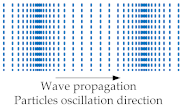 Adapted with permission from Ref. [2]. |
| Transverse wave | Propagation through the medium in the direction perpendicular to particle oscillation direction. It is also called shear-mode waves. | 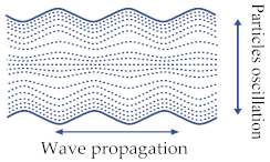 Adapted with permission from Ref. [1]. |
| Lamb wave | It exists in thin plates, also called the plate wave, and the particle motion lies in the plane that is perpendicular to the plate and the propagation direction of the wave [2]. It is divided into symmetric waves and antisymmetric waves [3]. | 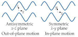 Adapted with permission from Ref. [3]. |
BAW resonators are a type of MEMS device experiencing acoustic wave propagation through the bulk of the medium. Currently, there are two main types of BAW resonators applied in the industry: thin-film BAW resonators (FBARs) [4][5][6] and solidly mounted resonators (SMRs) [6][7][8]. These two types of resonators have the same working principles but different fabrication technologies.
1.2. Bulk Vibration Modes
Based on the different acoustic wave propagation, BAW resonators vibrate with two types of motion: the in-plane motion and the out-of-plane motion. The in-plane vibrational modes mainly include the longitudinal mode and the anti-symmetric lamb mode, also called the flexural or bending mode [1], while the out-of-plane vibrational mode includes the transverse mode and the symmetric lamb mode, also known as the lateral bulk mode [9].
Note that the resonance frequency in BAW devices operating at the flexural (out-of-plane) mode is related and limited to the thickness of the device similar to the FBARs operating in the longitudinal mode [1]. Compared to flexural-mode devices, bulk-mode devices utilizing lateral in-plane vibration modes have a higher stiffness because of their higher bulk moduli [10]. Therefore, they vibrate at higher operational frequencies and are consequently less prone to internal mechanical losses, such as thermoelastic damping (TED), thereby achieving larger Q factors.
Over the past decades, two types of lateral bulk vibration modes have been mainly investigated for BAW resonators, with applications as oscillators, sensors, and filters: (i) the extensional (breathing) mode and the (ii) the WG mode of square-plate or disk structures [9][11][12][13][14][15][16][17][18]. Figure 1 and Figure 2 show a square plate and a disk BAW resonator, respectively, both exhibiting these two modes. Taking a square-plate BAW resonator as an example, the plate compresses and extends asymmetrically on the opposite sides in the WG mode, while it compresses and extends symmetrically on all four sides in the extensional mode [9].
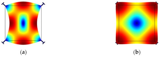
Figure 1. Finite element model (FEM) simulation of a BAW resonator with square plate structure in COMSOL. (a) WG mode; (b) Extensional mode.
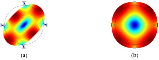
Figure 2. FEM simulation of a BAW resonator with disk structure in COMSOL. (a) WG mode; (b) Extensional mode.
It has been shown that the fundamental WG mode (WG1) can achieve a higher Q factor than the extensional mode [9]. A BAW resonator in air and even in liquid operating in higher-order WG modes (e.g., 2nd order WG mode [19] or the 3rd order WG mode [20]) usually has a higher Q factor than those working in the WG1 mode. Besides, for a disk resonator working in higher-order radial modes [21], the anchor loss is no longer the dominant source of energy dissipation. Other modes are also possible; Figure 3 shows some other bulk modes, such as the button-like (BL) [19], face-shear [22], and butterfly modes [23].
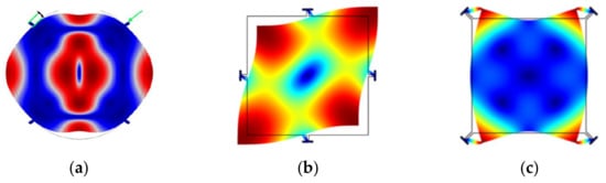
Figure 3. Other FEM simulated bulk modes in COMSOL. (a) BL mode (Adapted with permission from Ref. [17]); (b) Face-shear mode; (c) Butterfly mode.
1.3. BAW Resonators with Different Suspension Structures
The Q factor of a resonator is a dimensionless parameter to describe the loss of the vibration energy, defined by the ratio of the total energy stored with respect to the energy dissipated per cycle [9]. The energy losses can originate from different sources of energy dissipation. The clamping loss at anchors, also known simply as anchor loss, is a significant source of the energy loss mechanism, in particular when the anchors are stressed at the clamping points due to the displacement of the resonator during vibration. A fraction of the vibration energy stored is transferred to the substrate through the suspension stems and anchors [24][25].
The suspension structure also has a strong influence on the Q factor and also on the choice of the fabrication process. Two commonly used side-clamped suspensions, the simple straight-beam [9] and T-shaped suspensions [9][26] have already been widely employed in BAW resonators, as illustrated in Figure 4. The strain energy stored in the straight-beam suspension is related to the whole stem part. The strain energy stored in the T-shaped suspension is mostly associated with the cap because the stem part is decoupled from the anchor via the cap [9]. The ratio of the strain energy stored in the vibrating structure over the strain energy stored in the suspension part can be regarded as an indicator of anchor loss. The higher this ratio, the lower Q deduction induced by the anchor loss, especially when the anchor loss is the dominant energy dissipation mechanism in the system [9]. A method of calculating the strain distribution in the suspension part and resonator body using ANSYS FEA is proposed in [9][26], which could be helpful to design proper suspension structures.
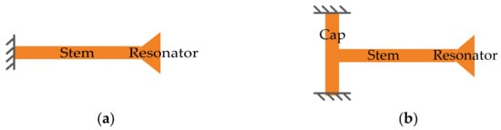
Figure 4. Schematic diagrams of suspensions. (a) Straight-beam suspension; (b) T-shaped suspension. Adapted with permission from Ref. [9].
Besides, the structure of the device can be clamped at different positions, such as the center (for surface micromachined structures) [27], the sides [22], and the corners [9][28] of the structure, as illustrated in Figure 5). How to choose the proper positions of the suspensions mainly depends on the minimum motion of working modes (to reduce the clamping loss as much as possible) and the fabrication possibility. Due to the manufacturing constraints, the sides and corners of the vibrating structure are commonly used locations for suspensions connected to the anchor, especially for designs with the backside substrate etched off for the releasing purpose. As for the devices with suspensions at the center, it is difficult to manage to fabricate devices with perfect suspension alignment. Perfect suspension alignment cannot guarantee high Q factors, for the suspension with finite dimensions will also restrict the motion outside the center part, which results in further energy losses [27]. Besides, Q factors are deduced with the mode number increasing since the device center is closer to the high-velocity points at higher modes. The misaligned suspension will couple the resonator vibration to the substrate, then the energy is lost to the substrate, thus the overall Q factor is degraded [27].
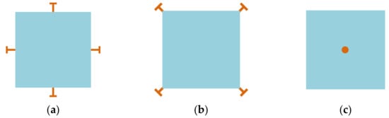
Figure 5. Suspensions at different positions: (a) On sides; (b) At corners; (c) At the center.
A study on the resonators with a different number of suspensions [29], indicates that a BAW resonator can vibrate in the expected modes even with a minimum of two suspensions. The anchor losses generally are lower with a low number of suspensions. However, the resonance frequency also decreases with a small number of suspensions, as fewer suspensions result in a decrease in the effective stiffness.
2. Multi Degrees-of-Freedom (Multi-DoF) Coupled BAW Resonators
2.1. Mass-Spring-Damper System for a Single Degree of Freedom (1-DoF) BAW Resonator
A single MEMS resonator can be modeled as a mechanical mass-spring-damper system with 1-DoF. As shown in Figure 6. M, K, and c represent the mass, the supporting spring stiffness, and the damping coefficient of the resonator, respectively.
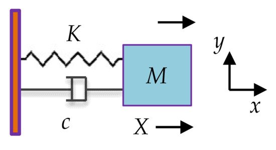
Figure 6. Mass-spring-damper model of a single resonator.
For a BAW resonator with a square plate structure using lateral vibration mode, the effective mass can be expressed as:
The effective stiffness is given by:
Therefore, the resonant frequency of the lateral modes like SE and WG modes can be approximately obtained by:
where L is the length of the square plate, h is the thickness, ρ denotes the density of the material of the plate, and E represents Young’s modulus.
2.2. Coupling Mechanisms
For multi-DoF BAW resonators, mechanical coupling in form of a mechanical spring or electrostatic coupling in form of an electrostatic spring can be used as a coupling mechanism [30][31], and this is illustrated in Figure 7. Both approaches can be regarded as equivalent in theoretical calculations and achieve the same level of effective coupling spring stiffness. When the coupling stiffness is much smaller than the stiffness of the suspension of the resonators, a weakly coupled system is formed. As for the strongly coupled system, if the coupling beam is set to be an integer number of half-wavelengths and the coupled system is operated at high frequencies, a very strong coupling element is achieved between the two resonators [32].
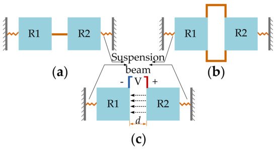
Figure 7. 2-DoF coupled BAW resonators with different coupling methods. (a) Fixed-fixed straight coupling beam; (b) Folded coupling beam; (c) Electrostatic coupling. Note: d is the lateral transduction gap between the resonator R1 and resonator R2, and the dotted arrow lines indicate the electric field direction.
However, the strong coupling does not apply to the VLF-MF flexural mode resonators, for at those high frequencies, the length of the coupling beam should reach hundreds of microns to be equal to the half-wavelengths, which is impractical for the real dimension design [32]. So far, there is less relevant work on the strongly coupled BAW resonators, and there is still no systematic theoretical model built. Therefore, the theory of the weakly coupled system will be mainly discussed. For the weakly coupled resonators, due to the fabrication tolerance, the structure likely becomes asymmetric, thus a pre-mode localization will occur. This caused a non-uniform energy distribution, but the structure symmetry still can be adjusted [32]. Moreover, a weakly coupled system will lead to a significant increase in sensitivity when coupled BAW resonators are used as sensors.
Two conventional designs of a mechanical coupling spring are the fixed-fixed guided beam and the folded coupling beam [31], as shown in Figure 7a and b respectively. The geometric parameters of the mechanical beams can be chosen to achieve different coupling strengths. The higher the ratio between length and width of a mechanical coupling spring, the weaker the coupling strength. Besides, the position of the coupling spring also has an obvious impact on the coupling strength, as shown in Figure 8.
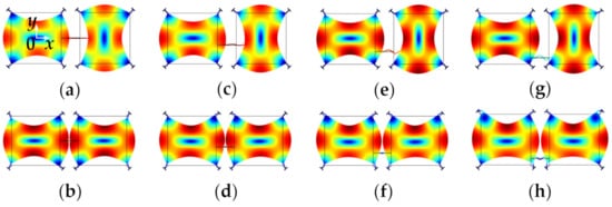
Figure 8. WG modes of a 2-DoF coupled BAW square plate resonator system with the same mechanical coupling beam located at different positions (represented by y) simulated in COMSOL. (a) Out-of-phase WG mode, y = 0 μm; (b) In-phase WG mode, y = 0 μm; (c) Out-of-phase WG mode, y = −100 μm; (d) In-phase WG mode, y = −100 μm; (e) Out-of-phase WG mode, y = −200 μm; (f) In-phase WG mode, y = −200 μm; (g) Out-of-phase WG mode, y = −300 μm; (h) In-phase WG mode, y = −300 μm. Note: y represents the y-axis value of the center location of the coupling beam, and the origin is at the center of the first square-plate proof mass. Note: There is a coordinate system in (a) with the original point set at the center of the left resonator. The y-axis value shows the position of the coupling beam. When the coupling beam is in the center position of both two resonators, y = 0. Then the beam moves down to the edge part, the y axis value is −100 μm, −200 μm, and −300 μm, respectively.
Figure 8 shows FEM simulated WG modes of a 2-DoF coupled BAW resonator system with a mechanical coupling beam of the same dimensions but located at different positions. The dimensions and material selection are listed in Table 2. The devices have different resonant frequencies of the in-phase and out-of-phase WG modes [33]. The coupling strength has an important influence on the frequency difference between the in-phase and out-of-phase modes of the 2-DoF resonator. A small coupling strength results in a small frequency difference between in-phase and out-of-phase modes as summarized in Table 1. As shown in Table 3, if the coupling beam is closer to the top or bottom sides of the proof mass, i.e., the square plate shown in Figure 8, the former in-phase mode frequency increases while the latter out-of-mode frequency decreases, and this means the frequency difference between these two modes decreases, and so does the coupling strength. The relationship between the frequency difference and the coupling strength for the 2-DoF coupled resonators can be calculated by Equations (4) and (5). Therefore, weak coupling can be achieved by adjusting the position of coupling beams without the need for changing the dimensions of the beams.
Table 2. Dimensions and materials of a 2-DoF coupled BAW square plate resonator system modeled in COMSOL (Adapted with permission from Ref. [9]).
| Parameters | Value |
|---|---|
| Length of the square plate (μm) | 800 |
| Thickness of the device (μm) | 25 |
| Length and width of the stem (μm) | 67.2 and 14.1 |
| Length and width of the cap (μm) | 70.7 and 10.6 |
| Length and width of the coupling beam (μm) | 400 and 14 |
| Materials selection for FEM simulation | Single crystal silicon (SCS) |
Table 3. The in-phase and out-of-phase mode resonant frequencies of a 2-DoF coupled BAW square plate resonator system with the same mechanical coupling beam located at different positions obtained by FEM simulation in COMSOL.
Location of Coupling BeamIn-Phase Mode (Hz)Out-of-Phase Mode (Hz)Frequency Differencey = 0 μm4,702,3894,769,160.741.42%y = −100 μm4,704,931.734,762,0911.21%y = −200 μm4,711,448.664,746,444.540.74%y = −300 μm4,717,826.994,730,406.990.27%
The electrostatic coupling (shown in Figure 7c) is achieved by applying a direct current (DC) voltage across a capacitive gap located between the two resonators [31]. The displacement-dependent component of the generated electrostatic force between the two resonators results in a spring-like behavior. The extension or compression direction of the electrostatic spring is aligned to the movement direction of the resonators, resulting in an elastic spring with negative effective spring stiffness. Note that the coupling strength can be easily tuned and controlled by changing the applied DC voltage. A very weak coupling can be achieved by applying a small DC voltage, which is much more convenient compared to mechanical coupling. However, the electrostatic coupling can be well applied to those coupled resonators with a low suspension spring, such as with the coupled double-ended tuning fork (DETF) resonators [34][35][36], where the mode aliasing effect can be avoided within a realistic range of DC voltages. Compared to DETF resonators [34][35][36], coupled BAW resonators using the lateral bulk mode (e.g., WG mode) have much higher effective stiffness, and thus a higher resonant frequency can be achieved. The electrostatic coupling strength (even the coupling voltage difference is under 300 V) is too small compared with the suspension spring stiffness of BAW resonators. That makes the electrostatically coupled BAW resonators prone to have the mode aliasing effect even with a high Q factor, as the generated frequency difference between in-phase and out-of-phase modes is too small to be told apart, within the working DC voltages.
Compared with the electrostatic coupling, the mechanical coupling has a higher stiffness (still smaller but not negligible compared with the suspension stiffness) and can be designed to avoid the mode aliasing and fulfill the requirement of the weak coupling at the same time. That is the reason why there is still no relevant research about the electrostatically coupled BAW resonators using the lateral vibration modes (the WG mode and extensional mode).
Figure 9 shows different vibration modes of a 2-DoF electrostatically coupled disk BAW resonator system. The dimensions and material selection are listed in Table 4. Each resonator has a short convex plate parallel to that of the other resonator to achieve electrostatic coupling, and a small potential difference of 100 V is applied to these two resonators. Two vibration modes are studied: Mode 1 with lower resonant frequencies and mode 2 (WG mode) with higher resonant frequencies. Table 5 summarizes their frequencies and shows that the frequency difference of WG mode 2 is about three orders of magnitude lower than that of mode 1. In conclusion, the mode with higher frequencies is more prone to mode aliasing than that operated at lower frequencies.
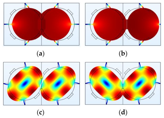
Figure 9. A 2-DoF electrostatically coupled BAW disk resonator system operating in different modes simulated in COMSOL. (a) Out-of-phase mode 1; (b) In-phase mode 1; (c) Out-of-phase mode 2 (WG mode); (d) In-phase mode 2 (WG mode). The deformation of resonators is magnified. In reality, the frequencies of the two modes are prone to be aliased due to the limited Q factor.
Table 4. Dimensions and materials of a 2-DoF electrostatically coupled BAW square resonator system modeled in COMSOL.
| Parameters | Value |
|---|---|
| Diameter of the disk plate (μm) | 1500 |
| Thickness of the device (μm) | 30 |
| Lateral transduction gap (μm) | 2 |
| Length and width of the stem (μm) | 225 and 37.5 |
| Length and width of the convex plate (μm) | 5.5 and 450 |
| Materials selection for FEM simulation | Single crystal silicon (SCS) |
Table 5. Differences in resonant frequencies of a 2-DoF electrostatically coupled BAW disk resonator system operated at different vibrational modes obtained by FEM simulation in COMSOL.
| Vibration Modes | Out-of-Phase Mode (Hz) | In-Phase Mode (Hz) | Frequency Difference |
|---|---|---|---|
| Mode 1 | 365,455.475 | 365,537.439 | 0.02% |
| Mode 2 (WG mode) | 2,654,149.09 | 2,654,150.75 | 0.00006% |
2.3. Mass-Spring-Damper System for 2-DoF Weakly Coupled BAW Resonators
As shown in Figure 10, a 2-DoF weakly coupled BAW resonator system is modeled as a mass-spring-damper system [30], where M1 and M2 are the mass of two resonators, K1 and K2 are the suspension spring stiffness, Kc is the stiffness of the coupling spring, c1 and c2 are the damping coefficient. Similarly, the displacements of the two resonators are X1 and X2, and the external forces applied to the two resonators are F1 and F2.
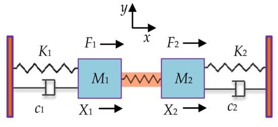
Figure 10. The lumped parameter model of a 2-DoF resonator.
Assuming F1 = F2 = 0 and c = 0, the resonant frequency of this system can be obtained, expressed as [30]:
2.4. Mass-Spring-Damper System for 3-DoF Weakly Coupled BAW Resonators
Figure 11 shows a 3-DoF weakly coupled BAW resonator system [30], M3 is the mass of resonator 3, K3 is the supporting spring stiffness, Kc1 and Kc2 are the stiffness of the coupling spring, and c3 is the damping. Similarly, the displacement of resonator 3 is X3, and the force applied to the three resonators is F1, F2, and F3, respectively.
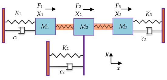
Figure 11. The lumped parameter model of a 3-DoF resonator.
Assuming F1 = F2 = F3 = 0 and c = 0, the resonant frequency of this system can be obtained, expressed as [37]:
2.5. Mode Aliasing
Unlike 1-DoF resonators, coupled resonators can exhibit multiple modes: 2-DoF coupled resonators normally exhibit two modes: in-phase and out-of-phase modes, and 3-DoF coupled resonators can exhibit three different in-phase and out-of-phase modes [30][34][35][36]. Different modes have different resonant frequencies as well as different working performances, such as the sensitivity performance when resonators serve as sensors.
However, due to the finite bandwidth of each mode, if the frequency difference between the adjacent two modes is too small, the two modes will interfere and merge, which results in only one observable resonant peak, and is called mode aliasing [35]. Therefore, once mode aliasing happens, the multiple modes of coupled resonators cannot be told apart and let along to use the characteristic of two modes for the sensing purpose. To reduce and avoid mode aliasing, the structure of resonators (especially the coupling strength) should be designed to achieve a large enough frequency difference between two adjacent modes, satisfying [35]:
where f3dB is the 3 dB bandwidth of each mode, f1 and f2 are the resonant frequency of two adjacent modes.
Additionally, different pairs of in-phase and out-of-phase vibration modes have different frequency differences. The WG mode with a relatively high frequency described above is more prone to the effect of mode aliasing than the mode with a lower frequency [30][34][35][36], as mentioned in Section 2.2.2, and the frequency differences of the mechanically coupled resonators operated in two modes (the same as the modes shown in Figure 9) are listed in Table 6. The data show that the frequency difference of mode 1 is much larger (more than 100 times larger) than that of WG mode, and this should be taken into consideration when you choose the proper working mode for your design of coupled BAW resonators, but currently, there is still no relevant study about this.
Table 6. Differences in resonant frequencies of a 2-DoF mechanically coupled BAW square resonator system operated at different vibrational modes obtained by FEM simulation in COMSOL.
| Vibrational Modes | In-Phase Mode (Hz) | Out-of-Phase Mode (Hz) | Frequency Difference |
|---|---|---|---|
| Mode 1 | 381,093.019 | 411,584.939 | 8% |
| Mode 2 (WG mode) | 4,711,448.66 | 4,746,444.54 | 0.74% |
3. Weakly Coupled BAW Resonators
3.1. Mode Localization
Weakly coupled BAW resonators normally indicate a situation where the coupling strength is far less than the supporting spring stiffness [30][38]. For the weakly coupled BAW resonators where two resonators are the same and there is no perturbation present, then the system is in balance, and the two resonators normally exhibit the same displacement. However, when a small external perturbation is introduced, the system will be imbalanced, and the vibrational energy will be mainly confined to only one resonator, the so-called mode localization phenomenon [39]. It has been proven that the sensitivity of weakly coupled resonators using the amplitude ratio |X1/X2| of two resonators as an output metric is several orders of magnitude higher than that using the conventional frequency shift as an output metric, which provides a new sensing mechanism with high sensitivity. As a result of the increase of the parametric sensitivity, the resolution limit of the mode-localized sensors can also be improved by orders of magnitude especially when more than 2-DoF resonators are coupled together, which has first been theoretically validated in [40].
Figure 12 shows two disk resonators that are weakly coupled together by a mechanical beam. The dimensions and material selection are listed in Table 7. For such a system, there are two types of vibration modes: the out-of-phase mode and the in-phase mode. Once a small mass perturbation is introduced into one of the resonators, the vibration amplitude [30] of the two resonators changes at the same time. The ratio |X1/X2| of the resonator amplitude at the same resonant frequency is then utilized for sensing applications. In Figure 13, the relationship between the relative mass change on resonator 2 and the amplitude ratio |X1/X2| is presented. When there is no mass perturbation in this system, the amplitude ratio is equal to 1, indicating both resonators have the same deformation. in the presence of a mass perturbation, the amplitude ratio is no longer equal to 1. Besides, the in-phase and out-of-phase modes have different mode shape changes with the same mass perturbation, which could be used to detect the position of the perturbation (for details see Section 2.3.4).
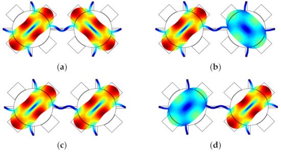
Figure 12. A 2-DoF weakly coupled BAW disk resonator system with mode localization simulated in COMSOL. (a) Out-of-phase mode without perturbation; (b) Out-of-phase mode with a small mass perturbation on the right resonator; (c) In-phase mode without perturbation; (d) In-phase mode with a small mass perturbation on the right resonator.
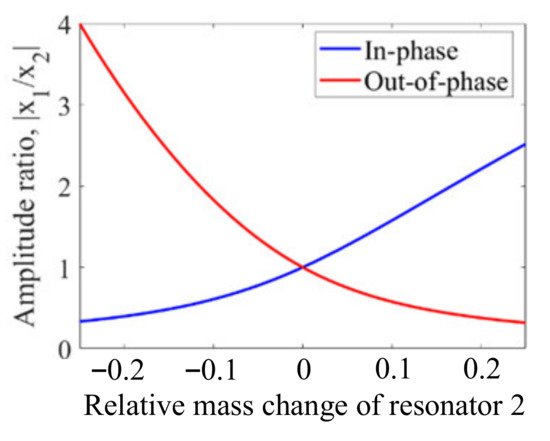
Figure 13. Relationship between the amplitude ratio change and the relative mass change on resonator 2.
Table 7. Dimensions and materials of a 2-DoF weakly coupled BAW disk resonator system modeled in COMSOL.
| Parameters | Value |
|---|---|
| Diameter of the disk plate (μm) | 200 |
| Thickness of the device (μm) | 30 |
| Lateral transduction gap (μm) | 2 |
| Length and width of the stem (μm) | 50 and 10 |
| Length and width of coupling beams (μm) | 125 and 10 |
| Materials selection for FEM simulation | Single crystal silicon (SCS) |
3.2. Sensitivity Characterization
When there is a change in mass or stiffness in the resonator system, i.e., ∆M or ∆K, the resonant frequency will change. Conventionally, the resonant frequency shift with respect to the stiffness and mass perturbation of the system is utilized to indicate the sensitivity of a resonator.
For the 1-DoF BAW resonators, when ∆M is far less than M, i.e., ∆M ≪ M, which is the same as ∆K ≪ K, the normalized sensitivity [41] based on the frequency shift with respect to a small ΔM or ΔK (M = M + ΔM or K = K + ΔK) is obtained as [30]:
Above all, when a 1-DoF system is exposed to a small perturbation, i.e., the stiffness or mass perturbation, there will be a 50% variation in the output frequency.
For the 2-DoF BAW resonator, the frequency shift with respect to a small ΔM or ΔK on resonator 2 (M2 = M + ΔM or K2 = K + ΔK) is used to characterize the normalized sensitivity which is obtained as:
For the 2-DoF BAW resonator based on the mode localization effect, the normalized sensitivity with respect to a small ΔM or ΔK on resonator 2 (M2 = M + ΔM or K2 = K + ΔK) represented by the amplitude change (X) is obtained as [30]:
Therefore, in terms of the amplitude change, the normalized sensitivity of the 2-DoF resonator is K/(2Kc) times larger than that of the 1-DoF resonator. However, when the amplitude ratio (AR) of the two resonators is adopted as an index to characterize the normalized sensitivity, the normalized sensitivity represented by the AR is obtained as:
where AR = |X1/X2|.
Compared to the normalized sensitivity obtained by the amplitude change, the normalized sensitivity is improved by 2 times with the usage of AR as the output metric. Thus, AR is widely taken as the output metric when the weakly coupled resonators based on mode localization are used as sensors, i.e., the mode-localized sensors.
For the 3-DoF mode localized BAW resonator as sensors, the normalized sensitivity with respect to a small ΔM or ΔK on resonator 3 (M3 = M + ΔM or K3 = K + ΔK) is obtained as [30][34][35][36]:
where AR = |X1/X3|.
The normalized sensitivity of the mode localized 3-DoF sensor is about two times higher than that of the 2-DoF resonator mode localized sensor, but if the stiffness K2 is designed to be two times or larger than K (Kc < K/10 < K2/20, K1 = K3 = K) [30][34][35][36], the normalized sensitivity can be expressed as:
The 3-DoF mode localized sensor has a sensitivity with the AR output which is at least 48 times higher than that of the 2-DoF resonator based on mode localization. Thus, there is plenty of room for adjusting the parameters of the coupled resonators to improve their sensitivity.
3.3. Common Mode Rejection
As for coupled BAW resonators with two identical resonators, any change in the ambient condition like a temperature fluctuation or a pressure fluctuation, causes a change in both resonators simultaneously, which is called the common-mode change [42][43]. The theoretical model of the temperature characteristics of the amplitude ratio and frequency of the mode-localized sensors under the influence of Young’s modulus has been established to reveal the common more-rejection property of the mode-localized sensors [44].
For example, in a 2-DoF weakly coupled resonator system with two identical resonators, the temperature (T) introduced stiffness change is ΔKT, which is applied to both resonators as a common-mode signal. Now let’s consider a situation in which a small external stiffness perturbation (ΔK) is applied to only one of the two resonators (e.g., resonator 2 here) in the presence of ΔKT:
Therefore, the sensitivity based on the frequency shift or the AR of the coupled resonators with two identical resonators is only related to the added stiffness perturbation (ΔK) and the influence of ΔKT on the sensitivity is canceled out as a common-mode signal. However, in reality, the two resonators are not fully identical due to fabrication errors, and the influence of ΔKT on the sensitivity (the frequency shift or the AR) can be reduced dramatically but not completely [42], as shown in Figure 14.
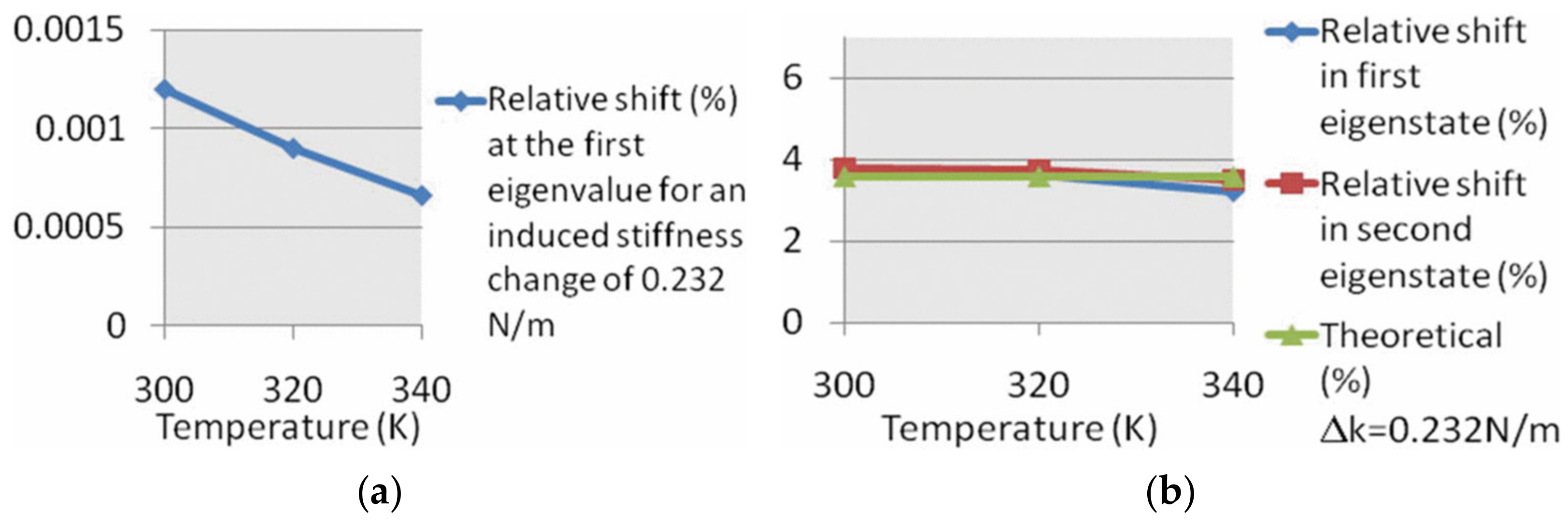
Figure 14. Effect of temperature change on the normalized sensitivity of resonators(Reprinted with permission from Ref. [42]). (a) 1-DoF resonators; (b) 2-DoF resonators.
Note that in the system of the 1-DoF resonator, there is only one resonator. Thus, when ΔKT and ΔK are both introduced to the resonator at the same time, the system stiffness Ks is:
The frequency shift is:
In this case, it is hardly clear whether the frequency shift is caused by the ΔKT or caused by the ΔK, making the sensors based on the 1-DoF resonator vulnerable to temperature fluctuation if no extra temperature compensation method is used.
3.4. Detection of the Position of Perturbations
For the coupled resonator, as mentioned above, the 2-DoF resonators normally have two different modes: in-phase and out-of-phase modes, and the 3-DoF coupled resonators can exhibit three different modes. Taking a 2-DoF weakly coupled BAW resonator system as an example, the relationship between the AR and mass perturbations on the resonator 2 is different when the resonator works in the in-phase or out-of-phase mode, as shown in Figure 12 and Figure 13. That is the case for the 3-DoF weakly coupled resonators as well. To conclude, to verify the position of the perturbation, the weakly coupled resonators can be driven selectively at their in-phase or out-of-phase mode, and then the corresponding ARs can be measured to locate the position of the perturbation accurately. Alternatively, researchers can employ the anti-resonances in the amplitude-frequency responses to identify which resonator is applied with a mass perturbation [45].
References
- Campanella, H. Acoustic Wave and Electromechanical Resonators: Concept to Key Applications; Artech House: Norwood, MA, USA, 2010.
- Su, Z.; Ye, L. Identification of Damage Using Lamb Waves: From Fundamentals to Applications; Springer: Berlin/Heidelberg, Germany, 2009; Volume 48.
- Li, S.-S.; Lin, Y.-W.; Ren, Z.; Nguyen, C.T.-C. An MSI Micromechanical Differential Disk-Array Filter. In Proceedings of the TRANSDUCERS 2007–2007 International Solid-State Sensors, Actuators and Microsystems Conference, Lyon, France, 10–14 June 2007; pp. 307–311.
- Ruby, R.C.; Bradley, P.; Oshmyansky, Y.; Chien, A.; Larson, J.D. Thin Film Bulk Wave Acoustic Resonators (FBAR) for Wireless Applications. In Proceedings of the 2001 IEEE Ultrasonics Symposium. Proceedings. An International Symposium (Cat. No.01CH37263), Atlanta, GA, USA, 7–10 October 2001; Volume 1, pp. 813–821.
- Mueller, W. A Brief Overview of FBAR Technology; Agilent Technologies Inc.: Santa Clara, CA, USA, 2001.
- Ruby, R.C. 11E-2 Review and Comparison of Bulk Acoustic Wave FBAR, SMR Technology. In Proceedings of the 2007 IEEE Ultrasonics Symposium Proceedings, New York, NY, USA, 28–31 October 2007; pp. 1029–1040.
- Lakin, K.M.; McCarron, K.T.; Rose, R.E. Solidly Mounted Resonators and Filters. In Proceedings of the 1995 IEEE Ultrasonics Symposium Proceedings. An International Symposium, Seattle, WA, USA, 7–10 November 1995; Volume 2, pp. 905–908.
- Lanz, R.; Muralt, P. Solidly Mounted BAW Filters for 8 GHz Based on AlN Thin Films. In Proceedings of the IEEE Symposium on Ultrasonics, Honolulu, HI, USA, 5–8 October 2003; Volume 1, pp. 178–181.
- Lee, J.E.Y.; Yan, J.; Seshia, A.A. Study of Lateral Mode SOI-MEMS Resonators for Reduced Anchor Loss. J. Micromechan. Microeng. 2011, 21, 045010.
- Chandrasekar, S.; Santhanam, S. A Calculation of the Bulk Modulus of Polycrystalline Materials. J. Mater. Sci. 1989, 24, 4265–4267.
- Kaajakari, V.; Mattila, T.; Oja, A.; Kiihamaki, J.; Kattelus, H.; Koskenvuori, M.; Rantakari, P.; Tittonen, I.; Seppa, H. Square-Extensional Mode Single-Crystal Silicon Micromechanical RF-Resonator. In Proceedings of the TRANSDUCERS ’03. 12th International Conference on Solid-State Sensors, Actuators and Microsystems. Digest of Technical Papers (Cat. No.03TH8664), Boston, MA, USA, 8–12 June 2003; Volume 2, pp. 951–954.
- Clark, J.R.; Hsu, W.-T.; Abdelmoneum, M.A.; Nguyen, C.T.-C. High-Q UHF Micromechanical Radial-Contour Mode Disk Resonators. J. Microelectromech. Syst. 2005, 14, 1298–1310.
- Basu, J.; Chakraborty, S.; Bhattacharyya, T.K. Micromechanical Radial-Contour Mode Disk Resonator for a CMOS-MEMS Oscillator. In Proceedings of the 2010 Annual IEEE India Conference (INDICON), Kolkata, India, 17–19 December 2010; pp. 1–4.
- Wang, J.; Ren, Z.; Nguyen, C.T.-C. 1.156-GHz Self-Aligned Vibrating Micromechanical Disk Resonator. IEEE Trans. Ultrason. Ferroelectr. Freq. Control 2004, 51, 1607–1628.
- Khine, L.; Palaniapan, M.; Wong, W.-K. 12.9 MHz Lame-Mode Differential SOI Bulk Resonators. In Proceedings of the TRANSDUCERS 2007–2007 International Solid-State Sensors, Actuators and Microsystems Conference, Lyon, France, 10–14 June 2007; pp. 1753–1756.
- Zarifi, M.H.; Daneshmand, M. Bulk Disc Resonators Radial and Wineglass Mode Resonance Characterization for Mass Sensing Applications. Microsyst. Technol. 2015, 22, 1013–1020.
- Hao, Z.; Pourkamali, S.; Ayazi, F. VHF Single-Crystal Silicon Elliptic Bulk-Mode Capacitive Disk Resonators-Part I: Design and Modeling. J. Microelectromech. Syst. 2004, 13, 1043–1053.
- Pourkamali, S.; Hao, Z.; Ayazi, F. VHF Single Crystal Silicon Capacitive Elliptic Bulk-Mode Disk Resonators-Part II: Implementation and Characterization. J. Microelectromech. Syst. 2004, 13, 1054–1062.
- Ali, A.; Lee, J.E.-Y. Piezoelectric Transduction of a Button-like Mode Disk Resonator for Enhanced Quality Factor in Water. In Proceedings of the 2017 Joint Conference of the European Frequency and Time Forum and IEEE International Frequency Control Symposium (EFTF/IFCS), Besancon, France, 9–13 July 2017; pp. 26–29.
- Ali, A.; Lee, J.E.-Y. Higher-Order Wine Glass Mode Piezoelectric Square Resonator with Improved Quality Factor in Water. In Proceedings of the 2017 IEEE SENSORS, Glasgow, UK, 29 October–1 November 2017; pp. 1–3.
- Shahraini, S.; Shahmohammadi, M.; Fatemi, H.; Abdolvand, R. Side-Supported Radial-Mode Thin-Film Piezoelectric-on-Silicon Disk Resonators. IEEE Trans. Ultrason. Ferroelectr. Freq. Control 2019, 66, 727–736.
- Lin, A.T.-H.; Yan, J.; Seshia, A.A. Electrostatically Transduced Face-Shear Mode Silicon MEMS Microresonator. In Proceedings of the 2010 IEEE International Frequency Control Symposium, Newport Beach, CA, USA, 1–4 June 2010; pp. 534–538.
- Prasad, A.; Charmet, J.; Seshia, A.A. Simultaneous Interrogation of High-Q Modes in a Piezoelectric-on-Silicon Micromechanical Resonator. Sens. Actuators A Phys. 2016, 238, 207–214.
- Yang, J.; Ono, T.; Esashi, M. Energy Dissipation in Submicrometer Thick Single-Crystal Silicon Cantilevers. J. Microelectromech. Syst. 2002, 11, 775–783.
- Li, W.-C.; Lin, Y.; Kim, B.; Ren, Z.; Nguyen, C.T.-C. Quality Factor Enhancement in Micromechanical Resonators at Cryogenic Temperatures. In Proceedings of the TRANSDUCERS 2009–2009 International Solid-State Sensors, Actuators and Microsystems Conference, Denver, CO, USA, 21–25 June 2009; pp. 1445–1448.
- Xu, Y.; Lee, J.E.-Y. Evidence on the Impact of T-Shaped Tether Variations on Q Factor of Bulk-Mode Square-Plate Resonators. In Proceedings of the 2012 7th IEEE International Conference on Nano/Micro Engineered and Molecular Systems (NEMS), Kyoto, Japan, 5–8 March 2012; pp. 463–468.
- Demirci, M.U.; Nguyen, C.T.-C. Mechanically Corner-Coupled Square Microresonator Array for Reduced Series Motional Resistance. J. Microelectromech. Syst. 2006, 15, 1419–1436.
- Lee, J.E.-Y.; Zhu, Y.; Seshia, A. A Bulk Acoustic Mode Single-Crystal Silicon Microresonator with a High-Quality Factor. J. Micromechan. Microeng. 2008, 18, 64001.
- Pachkawade, V.; Junghare, R.; Patrikar, R.; Kraft, M. Mechanically Coupled Ring-Resonator Filter and Array (Analytical and Finite Element Model). IET Comput. Digit. Technol. 2016, 10, 261–267.
- Zhao, C.; Montaseri, M.H.; Wood, G.S.; Pu, S.H.; Seshia, A.A.; Kraft, M. A Review on Coupled MEMS Resonators for Sensing Applications Utilizing Mode Localization. Sens. Actuators A Phys. 2016, 249, 93–111.
- Wang, Y. Mems Multi-Dof Weakly Coupled Resonator Based on Mode Localization for Mass Change Sensing Applications. Ph.D. Thesis, Université de Liège, Liège, Belgium, 2019.
- Erbes, A.; Thiruvenkatanathan, P.; Woodhouse, J.; Seshia, A.A. Numerical Study of the Impact of Vibration Localization on the Motional Resistance of Weakly Coupled MEMS Resonators. J. Microelectromech. Syst. 2015, 24, 997–1005.
- Thiruvenkatanathan, P.; Woodhouse, J.; Yan, J.; Seshia, A.A. Manipulating Vibration Energy Confinement in Electrically Coupled Microelectromechanical Resonator Arrays. J. Microelectromech. Syst. 2011, 20, 157–164.
- Zhao, C.; Wood, G.S.; Xie, J.; Chang, H.; Pu, S.H.; Chong, H.M.H.; Kraft, M. A Sensor for Stiffness Change Sensing Based on Three Weakly Coupled Resonators with Enhanced Sensitivity. In Proceedings of the 2015 28th IEEE International Conference on Micro Electro Mechanical Systems (MEMS), Estoril, Portugal, 18–22 January 2015; pp. 881–884.
- Zhao, C.; Wood, G.S.; Xie, J.; Chang, H.; Pu, S.H.; Kraft, M. A Force Sensor Based on Three Weakly Coupled Resonators with Ultrahigh Sensitivity. Sens. Actuators A Phys. 2015, 232, 151–162.
- Wang, Y.; Zhao, C.; Wang, C.; Cerica, D.; Baijot, M.; Xiao, Q.; Stoukatch, S.; Kraft, M. A Mass Sensor Based on 3-DOF Mode Localized Coupled Resonator under Atmospheric Pressure. Sens. Actuators A Phys. 2018, 279, 254–262.
- Siamak, H.-M. Capacitance readout circuits based on weakly-coupled resonators. Ph.D. Thesis, University of British Columbia, Vancouver, BC, Canada, June 2016.
- Ozgurluk, A. High-Q Strong Coupling Capacitive-Gap Transduced RF Micromechanical Resonators. Ph.D. Thesis, University of California, Berkeley, UC, USA, 10 January 2020.
- Anderson, P.W. Absence of Diffusion in Certain Random Lattices. Phys. Rev. 1958, 109, 1492–1505.
- Zhang, Z.; Chang, H. Resolution Limit of Mode-Localised Sensors. Sci. China Inf. Sci. 2021, 64, 142401.
- Golnaraghi, D.F.; Kuo, D.B.C. Automatic Control Systems, 10th ed.; McGraw-Hill Education: New York, NY, USA, 2017.
- Thiruvenkatanathan, P.; Yan, J.; Seshia, A.A. Common Mode Rejection in Electrically Coupled MEMS Resonators Utilizing Mode Localization for Sensor Applications. In Proceedings of the 2009 IEEE International Frequency Control Symposium Joint with the 22nd European Frequency and Time forum, Besancon, France, 20–24 April 2009; pp. 358–363.
- Thiruvenkatanathan, P. Mode-Localized Sensing in Micromechanical Resonator Arrays. Ph.D. Thesis, University of Cambridge, Cambridge, UK, 2011.
- Kang, H.; Ruan, B.; Hao, Y.; Chang, H. A Mode-Localized Resonant Accelerometer with Self-Temperature Drift Suppression. IEEE Sens. J. 2020, 20, 12154–12165.
- Zhang, H.; Chang, H.; Yuan, W. Characterization of Forced Localization of Disordered Weakly Coupled Micromechanical Resonators. Microsyst. Nanoeng. 2017, 3, 17023.
More
Information
Subjects:
Engineering, Electrical & Electronic
Contributors
MDPI registered users' name will be linked to their SciProfiles pages. To register with us, please refer to https://encyclopedia.pub/register
:
View Times:
2.6K
Revisions:
4 times
(View History)
Update Date:
06 Jun 2022
Table of Contents


Notice
You are not a member of the advisory board for this topic. If you want to update advisory board member profile, please contact office@encyclopedia.pub.
OK
Confirm
Only members of the Encyclopedia advisory board for this topic are allowed to note entries. Would you like to become an advisory board member of the Encyclopedia?
Yes
No
${ textCharacter }/${ maxCharacter }
Submit
Cancel
Back
Comments
${ item }
|
${ item.createdUser.fullName }
${ item.createdAt }
${ item.vote }
${ item.reply }
Delete
${ reply.createdUser.fullName }
${ reply.createdAt }
${ reply.vote }
Delete
There is no reply to this comment~
${ item.replyTextCharacter }/${ item.replyMaxCharacter }
Submit
Cancel
More
No more~
There is no comment~
${ textCharacter }/${ maxCharacter }
Submit
Cancel
${ selectedItem.replyTextCharacter }/${ selectedItem.replyMaxCharacter }
Submit
Cancel
Confirm
Are you sure to Delete?
Yes
No