Your browser does not fully support modern features. Please upgrade for a smoother experience.
Submitted Successfully!
 +1 credit
Thank you for your contribution! You can also upload a video entry or images related to this topic.
For video creation, please contact our Academic Video Service.
| Version | Summary | Created by | Modification | Content Size | Created at | Operation |
|---|---|---|---|---|---|---|
| 1 | Xinyang Su | -- | 5110 | 2022-06-01 07:11:21 | | | |
| 2 | Conner Chen | -38 word(s) | 5072 | 2022-06-01 08:10:58 | | | | |
| 3 | Conner Chen | -12 word(s) | 5060 | 2022-06-01 08:32:06 | | | | |
| 4 | Conner Chen | -2 word(s) | 5058 | 2022-06-06 09:11:04 | | |
Video Upload Options
We provide professional Academic Video Service to translate complex research into visually appealing presentations. Would you like to try it?
Cite
If you have any further questions, please contact Encyclopedia Editorial Office.
Su, X.; Zhu, R. Mid-Infrared Femtosecond Laser Based on Difference Frequency Generation. Encyclopedia. Available online: https://encyclopedia.pub/entry/23640 (accessed on 02 August 2026).
Su X, Zhu R. Mid-Infrared Femtosecond Laser Based on Difference Frequency Generation. Encyclopedia. Available at: https://encyclopedia.pub/entry/23640. Accessed August 02, 2026.
Su, Xinyang, Ruixue Zhu. "Mid-Infrared Femtosecond Laser Based on Difference Frequency Generation" Encyclopedia, https://encyclopedia.pub/entry/23640 (accessed August 02, 2026).
Su, X., & Zhu, R. (2022, June 01). Mid-Infrared Femtosecond Laser Based on Difference Frequency Generation. In Encyclopedia. https://encyclopedia.pub/entry/23640
Su, Xinyang and Ruixue Zhu. "Mid-Infrared Femtosecond Laser Based on Difference Frequency Generation." Encyclopedia. Web. 01 June, 2022.
Copy Citation
The mid-infrared (MIR) spectral region is known as the “molecular fingerprint region”, and almost every kind of gas molecule shows a unique and strong absorption characteristic within that region. The MIR ultrashort pulsed lasers can be widely used in gas detection, cancer diagnosis, pollutant monitoring, food quality control, and other aspects since they own much broader spectral ranges than ultrafast lasers in the visible and near-infrared region. There have been different techniques for the generation of ultrashort pulses in the MIR region of 2-5 µm. However, for the MIR ultrashort pulses generation at wavelengths longer than 5 µm or even 8 µm, difference frequency generation (DFG) is the primary technique.
mid-infrared
difference frequency generation
ultrafast laser
ultrashort pulse
beam quality
phase matching
optical parametric amplification
optical parametric oscillation
femtosecond
PPLN
1. Experimental Study of Long-Wavelength Mid-Infrared Laser Sources Based on DFG
Early DFG schemes are mainly based on bulky Ti: Sapphire femtosecond pulsed laser systems to generate dual-wavelength synchronous pulses, restricting the average power of the MIR below the milliwatt level due to the thermal load [1][2][3][4][5][6][7][8]. Modern DFG schemes that can achieve relatively high powers are mainly based on dual-wavelength OPO, OPA, and ultrafast fiber laser systems [9][10][11][12][13][14][15][16][17][18][19][20][21][22][23].
A MIR femtosecond pulsed laser with a wide tuning range (5–17 μm) and an average power of 69 mW at the wavelength of 6 μm was achieved by Beutler et al. based on the DFG in AgGaSe2 crystals utilizing a synchronously pumped OPO ultrafast laser source in 2015 [12]. A DFG-based MIR laser with an average power of 4.3 mW and a 10.5–16.5 μm wavelength-tunable range (as shown in Figure 1) was built by employing a two-color femtosecond OPO system in 2012 by Harald Giessen’s research group of the Fourth Institute of Physics at the University of Stuttgart, Germany [13]. Later in 2016, a highly stable MIR 350-fs pulsed laser system with nJ-level pulse energy and an ultra-wide tunability ranging from 1.33–2.0 μm and 2.13–20 μm has been achieved by Giessen’s group by combining OPO, OPA, and DFG technologies [14]. More recently, Wilson et al. proposed a DFG scheme for MIR generation tunable from 3.5 μm to 9 μm in 2019. They utilized a few-cycle Ti: Sapphire laser to pump an OPA to generate a total power of up to 6 mJ of signal (1300–1450 nm) and idler (1730–2000 nm) lights in the NIR. Then, the two synchronous pulses were used for the DFG process, and a maximum of 120 μJ at 5.3 μm and up to 80 μJ at 8.9 μm center wavelengths with 70–90 fs of pulse width were obtained through their setup (as shown in Figure 2) [15].
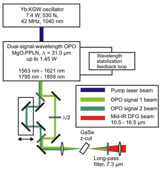
Figure 1. A 10.5–16.5 μm tunable femtosecond MIR pulsed laser system. Here, a 1 mm long MgO-doped periodically poled lithium niobate (PPLN) crystal is used for the dual-signal-wavelength OPO working at room temperature, which is synchronously pumped by a 1040 nm, 7.4 W, and 530 fs Yb: KGW oscillator at 42 MHz repetition rate. The dual-wavelength output beams of the OPO are focused on the GaSe crystal for DFG-based MIR generation.

Figure 2. A DFG scheme for MIR generation tunable from 3.5 μm to 9 μm [15]. An intense, few-cycle source in the long-wave infrared., Wilson, D.J.; Summers, A.M.; Zigo, S.; Davis, B.; Robatjazi, S.J.; Powell, J.A.; Rolles, D.; Rudenko, A.; Trallero-Herrero, C.A., COPYRIGHT 2019. (a) a 20 mJ Ti: Sapphire 800 nm laser is used to pump an optical parametric amplifier (OPA) with 18 mJ, 26 fs pulses at 1 kHz. A total of 6 mJ signal and idler pulses are generated from the OPA, and up to 4.2 mJ are used to generate LWIR (MIR) pulses via DFG in a AgGaS2 crystal (AGS) through type-I phase-matching. The residual pump and signal pulses are filtered by anti-reflective coated Zinc Selenide (ZS) and Germanium (Ge) windows. The Fresnel reflection of the Ge window is filtered with an additional Ge window so residual MIR power can be recorded on a pyroelectric detector (PyD) for power monitoring. A periscope sends the remaining pulse energy (>95%) into an experimental chamber with a ZS window, and then the MIR pulse is back-focused in Xenon (Xe) gas by a −25 mm spherical concave mirror (F). A pair of electrostatic lenses guide the Xe ions onto a micro-channel plate (MCP) detector for time-of-flight measurements. A small portion of the remaining 2 mJ OPA beam (pink) is used as a gating field in the XFROG. To perform electric field characterization, Mirror M is first removed from the periscope, and then the MIR pulse is coupled into the XFROG. (b) A typical time-of-flight spectrum for Xe+ when ionized with 8.9 μm pulse. (c) A measured XFROG spectrogram when the MIR laser pulse is working at 8.9 μm.
Ultrafast fiber lasers have been adopted as the pump sources in some DFG experiments due to their high surface-area-to-volume ratios, strong heat dissipation performances, high repetition rates and average powers, as well as all-fiber compactness. The output pulses from a fiber laser are usually divided into two parts for MIR generation. One part is used as pump pulses and the other produces a new spectral component on the longer wavelength side through the nonlinear fiber effect as wavelength-tunable signal pulses [16][17][18][19][20][21][22][23].
In 2013, Gambetta et al. reported a MIR pulsed laser with a tunability of 8–14 μm and a maximum average power of 4 mW in GaSe crystals (as shown in Figure 3) [17]. In the experiment, the Er: fiber laser oscillator (1.55 μm, 50 fs, and 550 mW) was used as the pump pulse, while the self-frequency shifted (SFS) soliton pulse (1.76–1.93 μm) generated from the nonlinear Raman fiber was serving as the signal pulse. The synchronism of the two pulses was adjusted through the optical delay line, and the tunable output of the MIR laser pulses was generated in a 1 mm-thick GaSe crystal. Zhou et al. developed a Yb: fiber laser system with an average power of 14.5 W, a repetition frequency of 30 MHz, and a pulse width of 165 fs. The output pulses of the system are divided into two parts in the optical path through the half-wave plate (HWP) and the polarization beam splitter (PBS). A portion of the pulses acted directly as pump pulses of the DFG. The other part of the pulses passed through a large-mode field fiber (4 cm), then the 125 fs signal pulses with the wavelength-tunable range of 1030–1215 nm were generated through the self-phase modulation effect. In the GaSe crystal, MIR pulses with a highest average power of 5.4 mW and a tunability between 7.4 and 18 μm (as shown in Figure 4) were finally obtained [20].
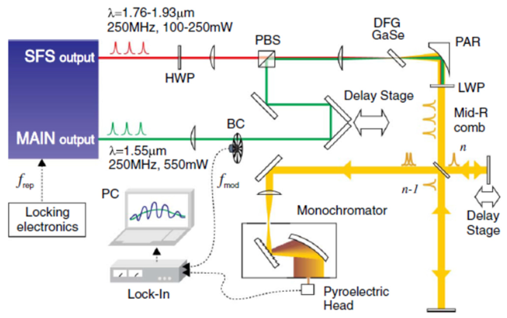
Figure 3. The 8–14 μm tunable MIR laser pulse generation. The experimental setup used for the mid-IR comb generation is based on a commercial dual-branch Er: fiber laser oscillator. The main output provides 1.55 μm, 550 mW, and 50 fs pulses, which are used as pump pulses. The second output produces tunable SFS solitons (as short as 84 fs) in the range 1.76–1.93 μm with an optical power varying from 100 to 250 mW by coupling pulse into a nonlinear Raman fiber, which are used as signal pulses.
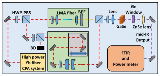
Figure 4. Schematic diagram of the ultrafast MIR sources with a tunable range of 7–18 μm. A home-built, 14.5 W, 165 fs, and 30 MHz Yb: fiber system is used as the front-end experimental setup for the MIR generation. The laser output is split into two paths by a half-wave plate (HWP) together with a polarization beam splitter (PBS). One path of light is coupled into a piece of large-mode-area (LMA) fiber for SPM-enabled spectra broadening, and then a bandpass filter is used for targeted wavelength selection to generate tunable femtosecond signal pulses. The other optical path serves as the pump for subsequent DFG in a GaSe crystal.
In 2019, Ma et al. proposed an all-polarization-maintaining fiber amplification method (except the optical delay line) for MIR generation [23]. The dual-wavelength pulses are split by an optical fiber coupler and enter different nonlinear amplification systems. Finally, the peak wavelengths of the two pulses are separated at least by 50 nm. The MIR generation from the system can be tuned from 7 to 10.5 µm. In 2018, Sotor et al. reported a MIR source ranging from 6 to 9 µm based on an all-fiber system [21]. The pulses from the oscillator were split and travelled through different fiber amplification models. However, a fiber-coupled delay line was used to control the synchronism of the pulses, making the front-end system truly all-fiberized (as shown in Figure 5). The maximum output power of the DFG was 7.4 mW with a repetition rate of 48 MHz at 7.5 µm, and the power was kept at 1 mW over the entire tuning range. More recently, Sotor et al. updated their system by adding a repetition rate stabilization model and a pulse-synchronism controlling model [22], which realized the stabilization of the repetition rate and the temporal pulse overlap in the MIR generation. An average power of 5 mW was obtained in the tunable range of 6.5–9 µm at 125 MHz (as shown in Figure 6).
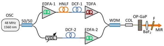
Figure 5. MIR source ranging from 6 to 9 µm based on an all-fiber system. The pulses from the Er-doped fiber oscillator (OSC) are equally split into two branches. One part is amplified in an Er: fiber amplifier (EDFA-1) to approximately 120 mW and enters a polarization-maintaining (PM) highly nonlinear fiber (HNLF). The spectrum of the input pulse is then shifted towards longer wavelengths via Raman-induced soliton self-frequency shift (SSFS) in the HNLF. Finally, the output pulses from the HNLF are amplified to 150–235 mW in a Tm: fiber amplifier (TDFA), serving as the signal pulses for the DFG process. The second part is amplified to 175 mW in EDFA-2. Both arms are combined together into a common single-mode fiber with a 1550/2000 nm wavelength division multiplexer (WDM). The temporal overlap between the pump and signal pulses is adjusted by a fiber-coupled variable delay line (VDL). The pump and signal beams are focused on the nonlinear crystal together for MIR generation. The generated MIR (idler) beam is collimated with a 75 mm barium fluoride (BaF2) lens. The residual pump and signal lights are blocked by a long-pass filter (F) with a 4.5 µm cut-on wavelength, meaning that only MIR pulses can travel through it.
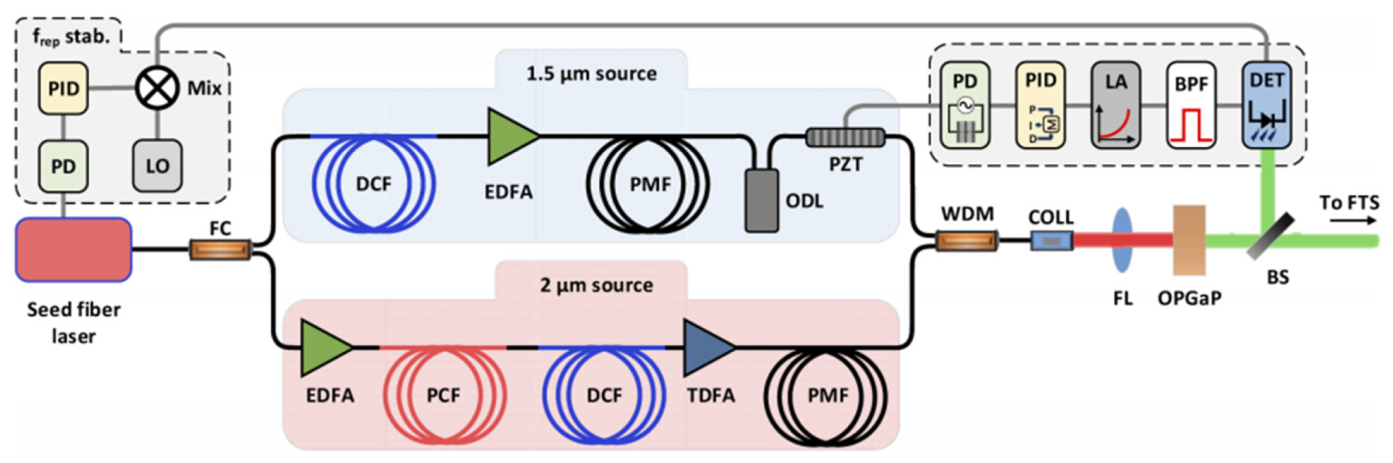
Figure 6. All-fiber MIR source with a tunable range of 6.5–9 µm. The system is composed of four main parts: (1) a mode-locked (ML) Er: fiber seed laser, (2) a 1.56 µm chirped pulse amplification (CPA) stage, (3) a stage for achieving a soliton shift for switching to 2 µm region and subsequent amplification of the ~2 µm red-shifted part of the spectrum through a CPA setup, and (4) difference frequency generation.
In recent years, the intrapulse difference frequency generation method (IDFG, also known as optical rectification) has become a new method to generate MIR laser source owning to its simplicity and phase stability [24][25][26][27][28][29][30][31][32][33][34][35][36][37][38][39][40][41]. The coherent femtosecond-level pulses with a wavelength range covering the whole MIR region are successively realized through IDFG. Only one beam of femtosecond pulses is needed to travel through the nonlinear crystal to obtain MIR pulses, making it structurally simpler than general DFG. However, IDFG involves a variety of nonlinear effects, and the mechanism is relatively unclear. The demand for relevant pump pulse width (usually few-cycle pulses) is also challenging to meet. Furthermore, tunability seems hard to realize since a very broad spectrum is generated via IDFG. In addition, for output wavelength longer than 10 μm, especially over 15 μm, the optical-optical conversion efficiency (MIR power/pump power) drops by tens of times compared to the short wavelength (see Table 1) regardless of the traditional DFG technology or the emerging IDFG technology.
Table 1. Studies on the generation of ultrafast MIR sources above 8 μm based on DFG and IDFG [24][25][26][27][28][29][30][31][32][33][34][35][36][37][38][39][40][41].
| Pump | MIR | Optical-Optical Conversion Efficiency | Repetition Rate | Method | Crystal | Reference |
|---|---|---|---|---|---|---|
| 800 nm, 4 W, 150 fs | 2.3 mW@11.5 μm Tunable 4–11.5 μm 410 fs@7.2 μm |
0.058%@11.5 μm | 80 MHz | DFG | LiInSe2 | [9] |
| 800 nm, 4 W, 150 fs | >0.5 mW@12 μm Tunable 4–12 μm |
0.013%@12 μm | 80 MHz | DFG | GaS0.4Se0.6 | [10] |
| 1034 nm, 5 W, 260 fs | ~25 mW@9 μm Tunable 5–12 μm 313 fs@7.2 μm |
~0.5%@9 μm | 53 MHz | DFG | LiInSe2 | [11] |
| 1034 nm, 5 W, 260 fs | 69 mW@6 μm ~25 mW@8.2 μm Tunable 5–17 μm 305 fs@7.2 μm |
1.4%@6 μm ~0.5%@8.2 μm |
53 MHz | DFG | AgGaSe2 | [12] |
| 1040 nm, 1.45 W, 250 fs | 4.3 mW@13.2 μm Tunable 10.5–16.5 μm |
0.29%@13.2μm | 42 MHz | DFG | AgGaSe2 | [13] |
| 1.03 μm, 7 W, 450 fs | 16 mW@15 μm, 0.6 mW@20 μm Tunable 1.33–20 μm 350 fs |
0.23%@15 μm 0.085%@20 μm |
43 MHz | DFG | AgGaSe2 | [14] |
| 800 nm, 18 mJ, 26 fs | 80 μJ@8.9 μm Tunable 3–9 μm 70–90 fs |
0.44%@8.9 μm | 1 kHz | DFG | AgGaS2 | [15] |
| 1.55 μm, 360 mW, 100 fs | 0.6–0.9 mW Tunable 3.7–20 μm |
0.16–0.25% | 40 MHz | DFG | GaSe | [16] |
| 1.55 μm, 550 mW, 50 fs | 4 mW@7.8 μm 1 mW@10.2 μm 0.11 mW@13.6 μm Tunable 8–14 μm |
0.72%@7.8 μm 0.18%@10.2 μm 0.02%@13.6 μm |
250 MHz | DFG | GaSe | [17] |
| 1035 nm, 1.3 W, 300 fs | ~135 µW@9 µm Tunable 4.2–9 μm |
~0.01%@9 µm | 40 MHz | DFG | AgGaS2 | [18] |
| 1.56 μm, 65 mW, 80 fs | 1.55 mW Spanning 7.5–11.6 μm 80 fs |
2.3% | 40 MHz | DFG | AgGaS2 | [19] |
| 1.03 μm, 6 W, 165 fs | 5.4 mW@9.5 μm 1.7 mW@16.7 μm Tunable 7–18 μm |
0.09%@9.5 μm 0.03%@16.7 μm |
30 MHz | DFG | GaSe | [20] |
| 1.56 μm, 175 mW, 76 fs | 7.4 mW@7.5 μm Tunable 6–9 μm |
4.2%@7.5 μm | 48 MHz | DFG | OP-GaP | [21] |
| 1.56 μm, 300 mW, 65 fs | 5 mW Tunable 6.5–9 µm |
1.7% | 125 MHz | DFG | OP-GaP | [22] |
| 1.56 μm, 150 mW, 47 fs | 120 µW@8 µm Tunable 7–10.5 µm |
0.08%@8 µm | 100 MHz | DFG | GaSe | [23] |
| 940 nm, 50 W, 19 fs | 103 mW Spanning 6.8–16.4 μm 66 fs@11.5 μm |
0.21% | 100 MHz | IDFG | GaSe | [24] |
| 1030 nm, 1 W, 30 fs | ~0.350 mW Spanning 8–11µm |
~0.035% | 50 kHz | IDFG | LiGaS2 | [25] |
| 2.1 μm, 250 μJ, 26 fs | 2 μJ@8.5 μm Spanning 7–11 μm |
0.8%@8.5 μm | 1 kHz | IDFG | AgGaSe2 | [26] |
| 600 nm, 350 mW, 10.6 fs | 0.25 mW Spanning 4–12 μm |
0.071% | 100 MHz | IDFG | OP-GaP | [27] |
| 2 μm, 18.7 W, 15 fs | 24 mW Spanning 4.5–20 μm |
0.13% | 77 MHz | IDFG | GaSe | [28] |
| 1.92 μm, 31.4 W, 110 fs | 450 mW Spanning 3.7–18 μm |
1.4% | 1.25 MHz | IDFG | GaSe | [29] |
| 2.1 μm, 1 W, 45 fs, | 15 mW Spanning 2–17 μm |
1.5% | 68.7 MHz | IDFG | GaSe | [30] |
| 3 μm, 95 μJ, 35 fs | 5 µJ, 50 mW Spanning 6–13.2 μm 68 fs@9.7 μm |
5.3% | 10 kHz | IDFG | GaSe | [31] |
| 2.1 μm, 7 W, 15 fs | 35 mW Spanning 2.7–20 μm |
0.5% | 77 MHz | IDFG | ZnSe/ZnS | [32] |
| 1.55 μm, 3.5 W, 30 fs | 25 mW Spanninng 4–20 μm |
0.71% | 100 MHz | IDFG | OP-GaP | [33] |
| 2.5 μm, 5.9 W, 20 fs | 13 mW Spanning 5.8–17.6 μm |
0.22% | 78 MHz | IDFG | GaSe | [34] |
| 2.5 μm, 4.5 W, 20 fs | 148 mW Spanning 5.8–12.5 μm |
3.3% | 78 MHz | IDFG | ZGP | [34] |
| 2 μm, 30 W, 32 fs | 0.5 W Spanning 6–18 μm 43 fs |
1.7% | 50 MHz | IDFG | GaSe | [35] |
| 2.4 µm, 1.1 W, 28 fs, | 1.9 mW Spanning 6–18 μm |
0.17% | 69 MHz | IDFG | BGSe | [36] |
| 1.55 μm, 800 mW, 15 fs | 70–100 μW Spanning 7–11 μm |
0.008–0.013% | 10 GHz | IDFG | OP-GaP | [37] |
| 1550 nm, 1.5 W, 10 fs | N/A Spanning 0.35–22.5 μm |
N/A | 100 MHz | IDFG | PPLN/CdSiP2/GaSe | [38] |
| 1040 nm, 11 W, 50 fs | 3.3 mW Tunable 7.5–11.2 μm |
0.03% | 43 kHz | IDFG | LiGaS2 | [39] |
| 2 μm, 374 mW, 6.8 fs | 860 μW@8.5 μm Spanning 6–22 μm 63 fs@8.5 μm 120 fs@10.7 μm |
0.23% | 100 MHz | IDFG | OP-GaAs/CdSiP2 | [40] |
| 1030 nm, 3.3 W, 12.1 fs | 1.2 mW Spanning 8.1–13.1 µm |
0.036% | 50 MHz | IDFG | OP-GaP | [41] |
Donna Strickland’s ultrafast laser group has been working on long-wavelength MIR pulse generation for tens of years, aiming on output wavelengths of over 16 μm based on the dual-wavelength ultrashort pulsed laser system and the DFG method [42][43][44][45][46]. In 2012, an 18 μm pulsed laser with an average power of 30 μW under subpicosecond level was achieved with the Yb: fiber amplification system, and the wavelength is tunable between 16 and 20 μm [44]. However, the experimental system is composed of bulk-optic elements, which is large, inefficient, and unstable. In 2018, they switched the whole bulk-optic system into a partially fiberized structure by replacing the traditional spatial grating with the chirped fiber Bragg grating as the wavelength selector, and two target wavelengths (1025 nm and 1085 nm) are selected. The dual-wavelength seed source was then amplified in the subsequent two-stage amplification system. As a result, the compact two-color femtosecond chirped pulse amplification (CPA) system with high average power (as shown in Figure 7) was achieved [45]. Furthermore, based on this system, a 17.4 μm MIR pulsed laser output with an average power of 2.5 mW was achieved by DFG under the condition of tight-focusing [46]. Compared to the previous work in 2012, not only was the MIR power increased by about 80 times, but the stability was also improved [44].
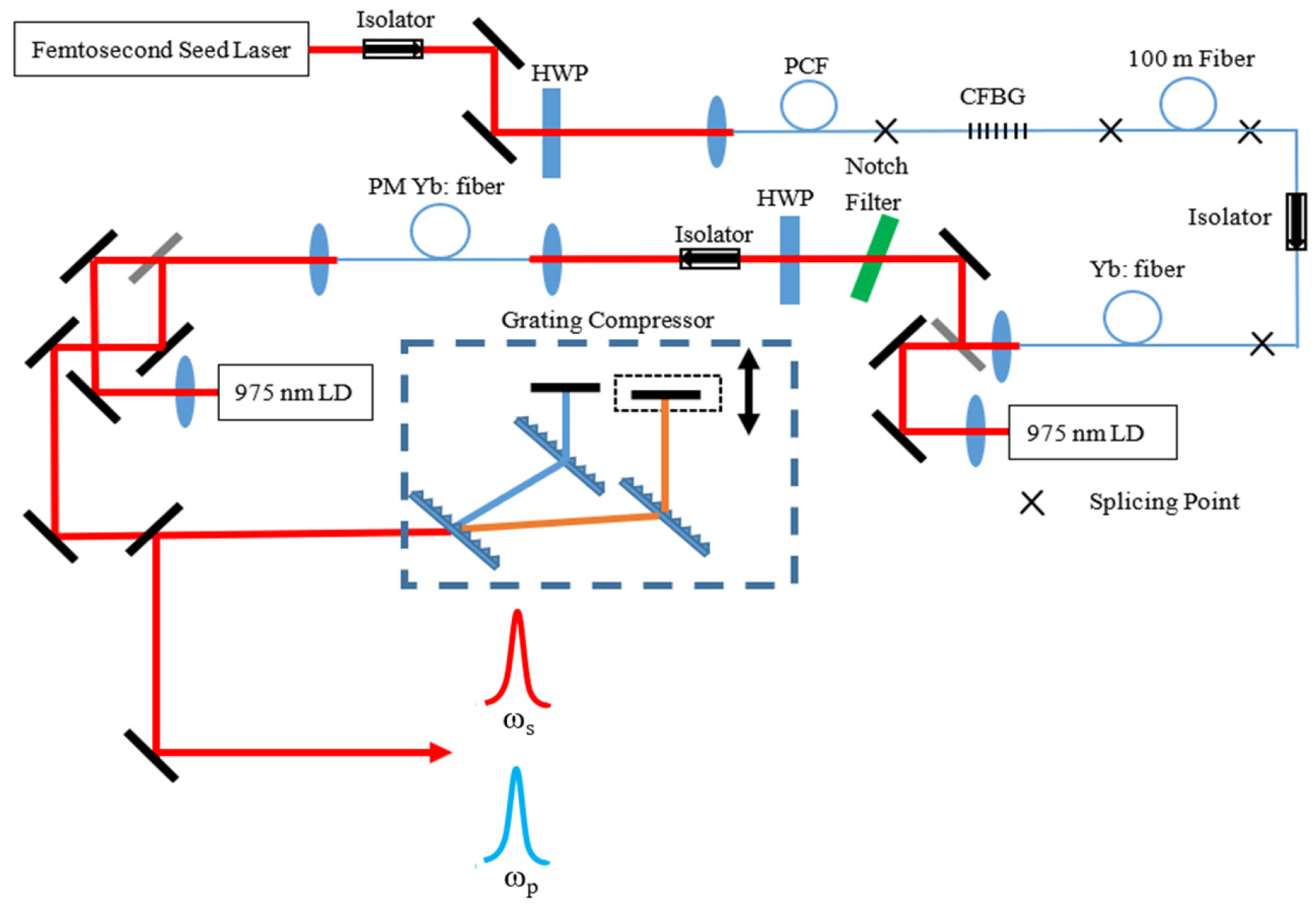
Figure 7. The dual-wavelength CPA system built by Donna Strickland’s group. A femtosecond laser system delivers 200 fs, 400 mW average power, and 65 MHz repetition rate laser pulses. The laser is then coupled into a photonic crystal fiber to achieve supercontinuum generation ranging from 900 to 1100 nm. A chirped fiber Bragg grating (CFBG) blocking the transmission from 1025 to 1085 nm is used to select the dual-wavelength seed source. Finally, the dual-wavelength seed source enters the CPA system to achieve final amplification with a total average power of 2.3 W (1.9 W at 1025 nm and 0.4 W at 1085 nm). The full width at half-maximum (FWHM) durations of the final compressed output pulses of each color are 900 fs and 600 fs, respectively.
In conclusion, the efficiency and stability of the current DFG laser systems can be vigorously improved if the following drawbacks can be addressed:
First of all, the components of the most current systems are partially fiberized, and structures of bulk-optic components are still adopted in the amplification and pulse compression modules, resulting in low conversion efficiency, significant loss, and strong instability.
Secondly, the increase of the total power of the amplification system is limited by the drawbacks in the process of seed spectrum selection and amplification. The effective spectral component that can be amplified in the seed spectrum selection process only accounts for less than one-tenth of the total power, and the other part of the energy in the supercontinuum is sacrificed. In addition, there are serious gain competitions in the amplification process when the dual-wavelength seeds are amplified simultaneously.
Thirdly, the impact of the accumulation of nonlinear phase shift on the final output pulse width is not considered in the whole CPA system. Compared with the initial seed pulse, the compressed pulse is wider and owns a prominent pedestal. The pulse quality still has a large room for improvement.
Last but not least, the generated MIR wavelength range can only cover 16–20 μm, which is a limited wavelength-tunable range. In addition, the power is also limited to several milliwatts. These two factors severely restrict the application field of the MIR laser source.
2. Theoretical Study of the DFG for Mid-Infrared Generation
In terms of theoretical research, there are few relevant theoretical calculations on transient DFG processes, and the transient model is usually complex. Therefore, the average power of the idler frequency light is always estimated with the steady-state DFG formula. However, since the formula is established under steady-state conditions, it is defective in the states of ultrashort pulses. To this end, the steady-state DFG formula should be modified. At present, the representative DFG formula of correction calculation of MIR power is as follows [47]:
In Equation (1), Tp, Ts, and Ti are Fresnel transmission coefficients of pump, signal, and idler pulse in nonlinear crystals, respectively. deff is the effective second-order nonlinear coefficient. Pp and Ps are the average powers of the pump and signal light. L is the interaction length of the pump, signal, and idler light in the nonlinear optical crystal. ε0 is the dielectric constant in the vacuum. c is the speed of light in the vacuum. ni, np, and ns are the refractive index of nonlinear optical crystals towards the idler, pump, and signal light at the phase-matching angle, respectively. λi is the wavelength of the idler pulse in a vacuum, f is the pulse repetition rate. t is the average value of the pump, signal, and idler pulse when the pulse widths of the three are assumed to be equal. g is the correction coefficient after considering the walk-off effect. The formula is modified compared to the DFG calculation formula in the continuous-wave state by taking the influence of peak powers into consideration. However, it is still a rough model because the value of the correction coefficient g (0 < g < 1) is not well defined. Moreover, the formula does not consider the thermal effect of the crystal, and there is a significant deviation between the calculation results and the actual experiments [44][47]. Therefore, the computational modified model of the average power of DFG should be reconstructed from the transient equation of the DFG process combined with an amount of experimental data.
Moreover, it is mentioned above that the physical process of OPA and DFG is basically equivalent, hence the generation of idler frequency light also happens in the realization of OPA. This raises new questions: can a critical condition be found during the DFG process by changing the laser power injected into nonlinear crystals to shift the DFG into the OPA process? If so, will the power of the idler frequency behave like an exponential nonlinear growth trend? Efforts have been made to explain the relevant problems through theoretical calculation. For the repetition rate of 30 MHz and the pulse width of 200 fs, the evolution curve of the idler pulse energy was obtained by varying with the pump and signal pulse energy, predicting that there are linear growth, nonlinear amplification, and saturation zones in the DFG process (as shown in Figure 8) [48]. It can be seen that when the signal light power is kept to a certain value, the pump power plays a decisive role in the improvement of the MIR (idler light) power, and the increase of the signal power can easily make the MIR power reach saturation. Therefore, when certain critical conditions of nonlinear amplification are met and the DFG process is transformed into an OPA process, the MIR power will be nonlinearly increased, and the optical-optical conversion efficiency will be greatly improved (>1%).
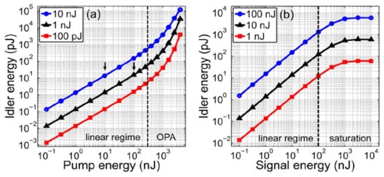
Figure 8. Energy evolution curve of idler pulse energy obtained through theoretical calculations. (a) Evolution of the idler energy versus the input pump energy when the input signal energy is fixed at 100 pJ, 1 nJ, and 10 nJ. (b) Evolution of the idler energy versus the input pump energy when the input signal energy is fixed at 1 nJ, 10 nJ, and 100 nJ. The thickness of GaSe crystal for MIR generation is 2 mm.
3. Feasibility of Mid-Infrared Power Scaling by Nonlinear-Amplification DFG
Regarding the current problems for MIR ultrashort pulse generation above 8 μm. They are as follows:
(1) For current MIR lasers based on DFG or IDFG schemes, when the output wavelength is longer than 10 μm or even longer than 15 μm, the power will drop rapidly to the order of several milliwatts, and the optical-optical conversion efficiency is relatively low.
(2) Most of the research groups separate the relationship between DFG and OPA, and do not consider the nonlinear amplification and saturation states that appear in the DFG process in theoretical and experimental research.
From the author’s point of view, there is no doubt that IDFG could generate broadband MIR sources with relatively higher powers. However, the problem is that the output MIR spectrum is not easily controllable and tunable. Except for picking up crystals with high nonlinearity and transmission, there is much work to be done in the front-end pumping system due to the complexity of overcoming dispersion and nonlinearity problems for obtaining the few-cycle pulses. Compared to IDFG, DFG is still a cost-effective scheme since fiber lasers under hundreds of femtosecond level as pump sources are commercially available and relatively economic. To solve the problem of low power of MIR for the DFG scheme, the following solutions with nonlinear-amplification DFG are proposed:
(1) Make reasonable adjustments to the focused beam size on the crystals. The focused spot size greatly affects the phase matching of the DFG process. In order to achieve high-power MIR pulsed laser under DFG scheme, an appropriate laser focusing lens should be selected to optimize the spot size focused on the nonlinear crystal. A small focused spot size will lead to a higher MIR power, but the divergence angle will be too large for the MIR beam to be collected and serious thermal effects and damaging problems will occur. On the other hand, the divergence angle will become small, and the MIR beam will be easy to collect when the focused spot size is large, but the intensity threshold of DFG in the nonlinear amplification region will not be reached. Therefore, the focused spot size should be optimized to make the focused light intensity higher than the threshold for nonlinear amplification and less than the crystal damage threshold to achieve high power MIR pulses.
(2) Adjust the power/pulse energy ratio entering the crystal. As predicted in [48], there are linear growth, nonlinear amplification and saturation regions in the DFG process. The MIR power is proportional to the product of the pump and signal light powers within a certain range. However, a large number of experiments show that it is not feasible to increase the signal power to the same level as the pump power since the wavelengths of the signal are usually not located in the gain curve of the materials. It is better to deliberately create a power gap between the pump and signal lights, which leads to the transformation of the linear growth state to the nonlinear amplification state and results in a conversion efficiency of >1%. Assuming a pump laser source with 10 W average power and a signal light with 100 mW average power, if the nonlinear amplification state is reached and kept, an average power of no less than 100 mW can be maintained throughout the whole MIR range.
4. Methods for Measuring the Power of DFG-Based Mid-Infrared
As shown in Figure 9, a large amount of thermal radiation is released from the back direction of the long-pass filter due to the strong absorption of pump and signal lights by the filter. Therefore, when the MIR power is measured by a thermal power meter behind the filter, the thermal radiation released from the filter will interfere with the measurement results, making the measured results much larger than the actual power. Under the condition of experiment, only one-third to one-fifth of the total measured power shown on the display of the power meter is the real power of the coherent mid-infrared source generated by DFG.
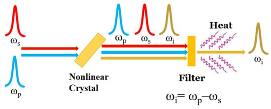
Figure 9. Heat effect during the DFG process.
In view of this, three measurement methods for measuring the power of DFG-based MIR will be tested here, and their pros and cons are also weighed. Before all the measurement work, all components to achieve the highest MIR power will be tweaked and adjusted.
Method 1: Nonlinear Crystal Rotating Method. Firstly, the total power of the MIR and the heat radiation by the filter is measured behind the filter. Then, the residual power (i.e., heat radiation) is measured when the output MIR disappears completely due to phase mismatch by slightly rotating the crystal by about 3°. Consequently, the power difference between the two measurements can be considered the actual MIR power. This method could achieve multiple measurements in a short time, since it is easy to restore the crystal to the position of the optimal phase-matching angle. The tweaked angle should not be more than 3° because the refraction of the crystal may affect the optical path.
Method 2: Pulse Synchronization Control method. As shown in Figure 7, the synchronism of the two pulses can be adjusted by the optical delay line placed behind the grating pulse compressors. When the two pulses are synchronized, the MIR power is the highest. First measure the power in this state. On the contrary, if the optical delay line is adjusted so that one pulse is far away from the other, the MIR will disappear. Then the MIR power could be determined by measuring the power difference between the two states. However, because the adjustment of the delay line is too fine, it is difficult to tweak back to the initial optimized position after one-time measurement, which means it will be hard to measure the power several times in a short time.
Method 3: Seed Laser Blocking Method. First measure the power after the filter as we did in method 1, and then use an opaque plate to block the output of the femtosecond seed laser. When the seed laser is blocked, only ASE exists in the dual-wavelength CPA system. In this state, MIR will not be generated anymore. Therefore, the MIR power can be determined by measuring the difference between the two states. Multiple measurements could also be achieved in a short time. However, because the total power of the ASE is not equal to that of the total amplified output power (the power of the ASE is usually lower than that of the power in the normal amplification state), the measurement results are relatively larger than the actual one.
The measurement results by the three methods are shown in Table 2 during experiment [46], which is the average value obtained by five-times repeating the measurement for each method. It can be seen from the table that the power value and standard deviation measured by method 3 are large due to the thermal effect of the filter, while the results measured by methods 1 and 2 are relatively close. Compared to method 1, a relatively lower result and larger deviation are obtained by method 2 due to the difficulty of tweaking the delay line back. Consequently, method 1 is strongly recommended in the power measurement of DFG-based MIR due to its advantage of simplicity and time-saving.
Table 2. Measured results by three different methods.
| Method 1 | Method 2 | Method 3 | |
|---|---|---|---|
| Power (mW) | 2.50 ± 0.19 | 2.19 ± 0.54 | 5.94 ± 0.58 |
5. Methods for Obtaining a High Beam Quality of DFG-Based Mid-Infrared
The beam quality of DFG-based MIR is also important since there are some application fields requiring high-quality MIR beams. The phase-matching condition largely affects the beam quality of DFG-based MIR, and the focused beam radius on the crystal and the crystal temperature are the main factors determining the phase-matching condition. Thus, there are mainly two ways to obtain a high beam quality of the MIR when applying the DFG method: controlling the focused beam size on the crystal or the crystal temperature.
With the tightly focused Gaussian beams, the optimum phase matching does not occur when Δk=0 (Δk=0 is the phase-mismatch vector) as in the plane wave approximation. As the focal spot size decreases to the dimensions of the MIR generated wavelengths, the axial phase matching is not optimized and the beam begins to propagate as conical emission, which will lower the beam quality. Consequently, a large-size focused beam with a radius of more than 100 μm on the crystal can ensure a better MIR beam quality [46][49].
The crystal temperature is another parameter to determine the MIR beam quality, and there have been some mode-control DFG experiments in the quasi-phase-matched periodically poled lithium niobate (PPLN) nonlinear crystals with different temperatures [50][51], as shown in Figure 10. Because the refractive index is highly related to the temperature in the PPLN crystal, the MIR beam profile is presented with different shapes in thermal imaging as the phase-mismatch vector varies with the temperature. Thus, it can be seen that temperature plays an important role in the MIR beam shaping under the condition of periodically poled crystals. However, there is almost no temperature-dependent research in the long-wavelength MIR region with other kinds of nonlinear crystals.
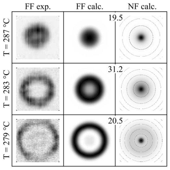
Figure 10. Experimental recordings and computations of the beam profile for three temperatures at normal incidence. Spatial mode control of radiation generated by DFG in periodically poled crystals.
Considering the currently reported works of the DFG-based MIR beam in the long-wavelength MIR region, thermal radiation is not a very big problem if the focused beam is large enough as most of the research group did not use a temperature-stabilized crystal oven. However, the thermal conductivity of the crystal is still an important parameter if the input peak intensity on the crystal reaches a relatively high value. According to reference [9], the thermal conductivity of LiGaS2 is 3 to 5 times higher than that of AgGaS2 and AgGaSe2 and ~2.5 times higher than the thermal conductivity of layered GaSe along its optic axis, and the thermal conductivity of LiGaS2 is 10.05 W/(m·k) [52]. However, the thermal conductivity of OP-GaP crystal is 110 W/(m·k) according to reference [22][41], which is the highest value. Thus, there is no doubt that OP-GaP is the preferable crystal for DFG-based MIR generation experiment if only take its thermal conductivity into consideration.
References
- de Barros, M.R.X.; Miranda, R.S.; Jedju, T.M.; Becker, P.C. High-repetition-rate femtosecond mid-infrared pulse generation. Opt. Lett. 1995, 20, 480–482.
- Fraser, J.M.; Wang, D.; Haché, A.; Allan, G.R.; van Driel, H.M. Generation of high-repetition-rate femtosecond pulses from 8 to 18 µm. Appl. Opt. 1997, 36, 5044–5047.
- Ehret, S.; Schneider, H. Generation of subpicosecond infrared pulses tunable between 5.2 μm and 18 μm at a repetition rate of 76 MHz. Appl. Phys. B Lasers Opt. 1998, 66, 27–30.
- Kaindl, R.A.; Smith, D.C.; Joschko, M.; Hasselbeck, M.P.; Woerner, M.; Elsaesser, T. Femtosecond infrared pulses tunable from 9 to 18 µm at an 88-MHz repetition rate. Opt. Lett. 1998, 23, 861–863.
- Kaindl, R.A.; Wurm, M.; Reimann, K.; Hamm, P.; Weiner, A.M.; Woerner, M. Generation, shaping, and characterization of intense femtosecond pulses tunable from 3 to 20 μm. J. Opt. Soc. Am. B 2000, 17, 2086–2094.
- Song, J.; Xia, J.F.; Zhang, Z.; Strickland, D. Mid-infrared pulses generated from the mixing output of an amplified, dual-wavelength Ti:sapphire system. Opt. Lett. 2002, 27, 200–202.
- Witte, T.; Kompa, K.L.; Motzkus, M. Femtosecond pulse shaping in the mid infrared by difference-frequency mixing. Appl. Phys. B Lasers Opt. 2003, 76, 467–471.
- Foreman, S.M.; Jones, D.J.; Ye, J. Flexible and rapidly configurable femtosecond pulse generation in the mid-IR. Opt. Lett. 2003, 28, 370–372.
- Beutler, M.; Rimke, I.; Büttner, E.; Petrov, V.; Isaenko, L. Femtosecond mid-IR difference-frequency generation in LiInSe2. Opt. Mater. Express 2013, 3, 1834–1838.
- Beutler, M.; Rimke, I.; Büttner, E.; Panyutin, V.; Petrov, V. 80-MHz difference-frequency generation of femtosecond pulses in the mid-infrared using GaS0.4Se0.6. Laser Phys. Lett. 2013, 10, 075406.
- Beutler, M.; Rimke, I.; Edlef, B.; Petrov, V.; Isaenko, L. Difference-frequency generation of fs and ps mid-IR pulses in LiInSe2 based on Yb-fiber laser pump sources. Opt. Lett. 2014, 39, 4353–4355.
- Beutler, M.; Rimke, I.; Büttner, E.; Farinello, P.; Agnesi, A.; Badikov, V.; Badikov, D.; Petrov, V. Difference-frequency generation of ultrashort pulses in the mid-IR using Yb-fiber pump systems and AgGaSe2. Opt. Express 2015, 23, 2730–2736.
- Hegenbarth, R.; Steinmann, A.; Sarkisov, S.; Giessen, H. Milliwatt-level mid-infrared (10.5–16.5 μm) difference frequency generation with a femtosecond dual-signal-wavelength optical parametric oscillator. Opt. Lett. 2012, 37, 3513–3515.
- Steinle, T.; Mörz, F.; Steinmann, A.; Giessen, H. Ultra-stable high average power femtosecond laser system tunable from 1.33 to 20 μm. Opt. Lett. 2016, 41, 4863–4866.
- Wilson, D.J.; Summers, A.M.; Zigo, S.; Davis, B.; Robatjazi, S.J.; Powell, J.A.; Rolles, D.; Rudenko, A.; Trallero-Herrero, C.A. An intense, few-cycle source in the long-wave infrared. Sci. Rep. 2019, 9, 3–9.
- Keilmann, F.; Amarie, S. Mid-infrared frequency comb spanning an octave based on an Er fiber laser and difference-frequency generation. J. Infrared Millim. Terahertz Waves 2012, 33, 479–484.
- Gambetta, A.; Coluccelli, N.; Cassinerio, M.; Gatti, D.; Laporta, P.; Galzerano, G.; Marangoni, M. Milliwatt-level frequency combs in the 8–14 μm range via difference frequency generation from an Er:fiber oscillator. Opt. Lett. 2013, 38, 1155–1157.
- Yao, Y.; Knox, W.H. Broadly tunable femtosecond mid-infrared source based on dual photonic crystal fibers. Opt. Express 2013, 21, 26612–26619.
- Churin, D.; Kieu, K.; Norwood, R.A.; Peyghambarian, N. Efficient frequency comb generation in the 9-μm region using compact fiber sources. IEEE Photonics Technol. Lett. 2014, 26, 2271–2274.
- Zhou, G.; Cao, Q.; Kärtner, F.X.; Chang, G. Energy scalable, offset-free ultrafast mid-infrared source harnessing self-phase-modulation-enabled spectral selection. Opt. Lett. 2018, 43, 2953–2956.
- Sotor, J.; Martynkien, T.; Schunemann, P.G.; Mergo, P.; Rutkowski, L.; Soboń, G. All-fiber mid-infrared source tunable from 6 to 9 μm based on difference frequency generation in OP-GaP crystal. Opt. Express 2018, 26, 11756–11763.
- Krzempek, K.; Tomaszewska, D.; Głuszek, A.; Martynkien, T.; Mergo, P.; Sotor, J.; Foltynowicz, A.; Soboń, G. Stabilized all-fiber source for generation of tunable broadband fCEO-free mid-IR frequency comb in the 7–9 µm range. Opt. Express 2019, 27, 37435–37445.
- Ma, J.; Lu, Q.; Duan, D.; Yao, B.; Mao, Q. A Broadband Infrared DFG Optical Comb Using All-PM Nonlinear Pulse Fiber Amplification Technique. IEEE Photonics Technol. Lett. 2019, 31, 439–442.
- Pupeza, I.; Sanchez, D.; Zhang, J.; Lilienfein, N.; Seidel, M.; Karpowicz, N.; Paasch-Colberg, T.; Znakovskaya, I.; Pescher, M.; Schweinberger, W.; et al. High-power sub-two-cycle mid-infrared pulses at 100 MHz repetition rate. Nat. Photonics 2015, 9, 721–724.
- Chen, B.-H.; Nagy, T.; Baum, P. Efficient middle-infrared generation in LiGaS2 by simultaneous spectral broadening and difference-frequency generation. Opt. Lett. 2018, 43, 1742–1745.
- Novák, O.; Krogen, P.R.; Kroh, T.; Mocek, T.; Kärtner, F.X.; Hong, K.-H. Femtosecond 8.5 μm source based on intrapulse difference-frequency generation of 2.1 μm pulses. Opt. Lett. 2018, 43, 1335–1338.
- Timmers, H.; Kowligy, A.; Lind, A.; Cruz, F.C.; Nader, N.; Silfies, M.; Ycas, G.; Allison, T.K.; Schunemann, P.G.; Papp, S.B.; et al. Molecular fingerprinting with bright, broadband infrared frequency combs. Optica 2018, 5, 727–732.
- Zhang, J.; Fai Mak, K.; Nagl, N.; Seidel, M.; Bauer, D.; Sutter, D.; Pervak, V.; Krausz, F.; Pronin, O. Multi-mW, few-cycle mid-infrared continuum spanning from 500 to 2250 cm−1. Light Sci. Appl. 2018, 7, 17180.
- Gaida, C.; Gebhardt, M.; Heuermann, T.; Stutzki, F.; Jauregui, C.; Antonio-Lopez, J.; Schülzgen, A.; Amezcua-Correa, R.; Tünnermann, A.; Pupeza, I.; et al. Watt-scale super-octave mid-infrared intrapulse difference frequency generation. Light Sci. Appl. 2018, 7, 94.
- Wang, Q.; Zhang, J.; Kessel, A.; Nagl, N.; Pervak, V.; Pronin, O.; Mak, K.F. Broadband mid-infrared coverage (2–17 μm) with few-cycle pulses via cascaded parametric processes. Opt. Lett. 2019, 44, 2566–2569.
- Liu, K.; Liang, H.; Qu, S.; Li, W.; Zou, X.; Zhang, Y.; Wang, Q.J. High-energy mid-infrared intrapulse difference-frequency generation with 53% conversion efficiency driven at 3 µm. Opt. Express 2019, 27, 37706–37713.
- Zhang, J.; Fritsch, K.; Wang, Q.; Krausz, F.; Mak, K.F.; Pronin, O. Intra-pulse difference-frequency generation of mid-infrared (2.7–20 μm) by random quasi-phase-matching. Opt. Lett. 2019, 44, 2986–2989.
- Kowligy, A.S.; Timmers, H.; Lind, A.J.; Karlen, S.; Cruz, F.; Schunemann, P.G.; Biegert, J.; DIddams, S.A. Near-Single-Cycle Long-Wave Infrared Pulses for Coherent Linear and Nonlinear Optics. In Proceedings of the Conference on Lasers and Electro-Optics Science and Innovations 2019, San Jose, CA, USA, 5–10 May 2019; Volume 1, pp. 39–40.
- Vasilyev, S.; Moskalev, I.S.; Smolski, V.O.; Peppers, J.M.; Mirov, M.; Muraviev, A.V.; Zawilski, K.; Schunemann, P.G.; Mirov, S.B.; Vodopyanov, K.L.; et al. Super-octave longwave mid-infrared coherent transients produced by optical rectification of few-cycle 2.5-μm pulses. Optica 2019, 6, 111–114.
- Butler, T.P.; Gerz, D.; Hofer, C.; Xu, J.; Gaida, C.; Heuermann, T.; Gebhardt, M.; Vamos, L.; Schweinberger, W.; Gessner, J.A.; et al. Watt-scale 50-MHz source of single-cycle waveform-stable pulses in the molecular fingerprint region. Opt. Lett. 2019, 44, 1730–1733.
- Zhang, J.; Wang, Q.; Hao, J.; Liu, H.; Yao, J.; Li, Z.; Liu, J.; Mak, K.F. Broadband, few-cycle mid-infrared continuum based on the intra-pulse difference frequency generation with BGSe crystals. Opt. Express 2020, 28, 37903–37909.
- Kowligy, A.S.; Carlson, D.R.; Hickstein, D.D.; Timmers, H.; Lind, A.J.; Schunemann, P.G.; Papp, S.B.; Diddams, S.A. Mid-infrared frequency combs at 10 GHz. Opt. Lett. 2020, 45, 3677–3680.
- Lesko, D.M.B.; Timmers, H.; Xing, S.; Kowligy, A.; Lind, A.J.; Diddams, S.A. A six-octave optical frequency comb from a scalable few-cycle erbium fibre laser. Nat. Photonics 2021, 15, 281–286.
- Wang, W.; Wu, H.; Liu, C.; Sun, B.; Liang, H. Multigigawatt 50 fs Yb:CALGO regenerative amplifier system with 11 W average power and mid-infrared generation. Photonics Res. 2021, 9, 1439–1445.
- Xing, S.; Lesko, D.M.B.; Umeki, T.; Lind, A.J.; Hoghooghi, N.; Wu, T.H.; Diddams, S.A. Single-cycle all-fiber frequency comb. APL Photonics 2021, 6, 086110.
- Nakamura, T.; Badarla, V.R.; Hashimoto, K.; Schunemann, P.G.; Ideguchi, T. A simple approach of broadband mid-infrared pulse generation with a mode-locked Yb-doped fiber laser. Opt. Lett. 2022, 47, 1790–1793.
- Romero-Alvarez, R.; Pettus, R.; Wu, Z.; Strickland, D. Two-color fiber amplifier for short-pulse, mid-infrared generation. Opt. Lett. 2008, 33, 1065–1067.
- Al-Kadry, A.M.; Strickland, D. Generation of 400 μW at 17.5 μm using a two-color Yb fiber chirped pulse amplifier. Opt. Lett. 2011, 36, 1080–1082, Erratum in Opt. Lett. 2018, 43, 316–316.
- Hajialamdari, M.; Strickland, D. Tunable mid-infrared source from an ultrafast two-color Yb:fiber chirped-pulse amplifier. Opt. Lett. 2012, 37, 3570–3572, Erratum in Opt. Lett. 2018, 43, 353–353.
- Su, X.; Hoang, T.; Long, P.; Zheng, Y.; Strickland, D. A Compact High-Average-Power Femtosecond Fiber-Coupled Two-Color CPA System. IEEE J. Sel. Top. Quantum Electron. 2018, 24, 0902905.
- Su, X.; Lyu, M.; Hoang, T.; Xu, Z.; Zheng, Y.; Strickland, D. Investigation of long wavelength mid-infrared generation in the tight focusing limit. Opt. Express 2019, 27, 24945–24952.
- Hajialamdari, M. Tunable Two-Color Ultrafast Yb: Fiber Chirped Pulse Amplifier: Modeling, Experiment, and Application in Tunable Short-Pulse Mid-Infrared Generation; University of Waterloo: Waterloo, ON, Canada, 2013.
- Cao, Q.; Kärtner, F.X.; Chang, G. Towards high power longwave mid-IR frequency combs: Power scalability of high repetition-rate difference-frequency generation. Opt. Express 2020, 28, 1369–1384.
- Morris, J.R.; Shen, Y.R. Theory of far-infrared generation by optical mixing. Phys. Rev. A 1977, 15, 1143–1156.
- Giusfredi, G.; Mazzotti, D.; Cancio, P.; De Natale, P. Spatial mode control of radiation generated by frequency difference in periodically poled crystals. Phys. Rev. Lett. 2001, 87, 113901.
- Malara, P.; Maddaloni, P.; Mincuzzi, G.; De Nicola, S.; De Natale, P. Non-collinear quasi phase matching and annular profiles in difference frequency generation with focused Gaussian beams. Opt. Express 2008, 16, 8056–8066.
- Kurus, A.; Yelisseyev, A.; Lobanov, S.; Plyusnin, P.; Molokeev, M.; Solovyev, L.; Samoshkin, D.; Stankus, S.; Melnikova, S.; Isaenko, L. Thermophysical properties of lithium thiogallate that are important for optical applications. RSC Adv. 2021, 11, 39177–39187.
More
Information
Subjects:
Optics
Contributors
MDPI registered users' name will be linked to their SciProfiles pages. To register with us, please refer to https://encyclopedia.pub/register
:
View Times:
2.3K
Revisions:
4 times
(View History)
Update Date:
06 Jun 2022
Table of Contents


Notice
You are not a member of the advisory board for this topic. If you want to update advisory board member profile, please contact office@encyclopedia.pub.
OK
Confirm
Only members of the Encyclopedia advisory board for this topic are allowed to note entries. Would you like to become an advisory board member of the Encyclopedia?
Yes
No
${ textCharacter }/${ maxCharacter }
Submit
Cancel
Back
Comments
${ item }
|
${ item.createdUser.fullName }
${ item.createdAt }
${ item.vote }
${ item.reply }
Delete
${ reply.createdUser.fullName }
${ reply.createdAt }
${ reply.vote }
Delete
There is no reply to this comment~
${ item.replyTextCharacter }/${ item.replyMaxCharacter }
Submit
Cancel
More
No more~
There is no comment~
${ textCharacter }/${ maxCharacter }
Submit
Cancel
${ selectedItem.replyTextCharacter }/${ selectedItem.replyMaxCharacter }
Submit
Cancel
Confirm
Are you sure to Delete?
Yes
No