Your browser does not fully support modern features. Please upgrade for a smoother experience.
Submitted Successfully!
 +1 credit
Thank you for your contribution! You can also upload a video entry or images related to this topic.
For video creation, please contact our Academic Video Service.
| Version | Summary | Created by | Modification | Content Size | Created at | Operation |
|---|---|---|---|---|---|---|
| 1 | Janusz Piechna | -- | 1765 | 2022-04-07 09:06:00 | | | |
| 2 | Conner Chen | -8 word(s) | 1757 | 2022-04-08 05:09:00 | | |
Video Upload Options
We provide professional Academic Video Service to translate complex research into visually appealing presentations. Would you like to try it?
Cite
If you have any further questions, please contact Encyclopedia Editorial Office.
Piechna, J. Active Aerodynamic Systems for Road Vehicles. Encyclopedia. Available online: https://encyclopedia.pub/entry/21443 (accessed on 18 July 2026).
Piechna J. Active Aerodynamic Systems for Road Vehicles. Encyclopedia. Available at: https://encyclopedia.pub/entry/21443. Accessed July 18, 2026.
Piechna, Janusz. "Active Aerodynamic Systems for Road Vehicles" Encyclopedia, https://encyclopedia.pub/entry/21443 (accessed July 18, 2026).
Piechna, J. (2022, April 07). Active Aerodynamic Systems for Road Vehicles. In Encyclopedia. https://encyclopedia.pub/entry/21443
Piechna, Janusz. "Active Aerodynamic Systems for Road Vehicles." Encyclopedia. Web. 07 April, 2022.
Copy Citation
Comfort, safety, high travel speeds, and low fuel consumption are expected characteristics of modern cars. Some of these are in conflict with one other. A solution to this conflict may be time-varying body geometry realized by moving aerodynamic elements and appropriate systems for controlling their motion.
vehicle aerodynamics
active aerodynamic
1. Introduction
The influence of aerodynamics on vehicle behavior has been known for years. This influence was mainly observed during various types of races when vehicle speeds were high. For many years, it was believed that its main manifestation was aerodynamic drag. Therefore, efforts were made for vehicles to have the lowest possible aerodynamic drag coefficients and a small frontal area. Attempts were made to reduce the observed instability at high speeds using vertical stabilizers. The stabilizers worked, but only for large angular deviations of the vehicles from the assumed direction of travel. The relationship between vehicle dynamics and the aerodynamic vertical force generated by the bodies was identified relatively late. Previously unexplained symptoms of directional instability occurring at high speeds in vehicles with low aerodynamic drag began to be linked to the aerodynamic lift force generated on them, which reduced the force acting on the rear wheels at high speeds, causing their sideslip angles to increase, which was a direct cause of instability.
Work commenced to develop vehicles with aerodynamic elements pressing the vehicle against the road. However, generating aerodynamic downforce came at the cost of increased aerodynamic drag. The natural solution was to use moving aerodynamic elements at lower speeds during cornering, which were turned off at high speeds on straight sections of the track. This was extremely effective, but as a result of underestimating the increase in vehicle performance during cornering, the design solutions proved to be too fragile and dangerous. As a result of several accidents on the track, this type of solution was banned. This state of affairs continued for decades.
Increasing knowledge of vehicle dynamics and the development of computers led researchers to other ways of using moving aerodynamic elements. Analyses of the relationship between ride comfort and grip on rough roads using only mechanical elements, springs, and shock absorbers, showed the impassable limits of possible solutions. The time-varying external forces offered by aerodynamics were used to circumvent them.
Analyses of the operation of moving aerodynamic elements are usually carried out in two different ways, unfortunately independently of each other. Control models of these elements are built based on vehicle dynamics models of varying complexity, but always with simplified models of the moving aerodynamic elements. There are only a few papers that include theoretical control models with full vehicle aerodynamics models. Complex car dynamics models have been built to consider the moving aerodynamic elements of a car but without control systems.
Yu and Gao [1] and Gao et al. [2] reviewed the influence of active aerodynamic tails on vehicle handling stability and the state of the art in active aerodynamic control research for vehicles, but only from the point of view of control system specialists.
2. Existing Technical Solutions
The aerodynamics of road vehicles in the early period of their development benefited from the experience of aeronautical aerodynamics gained earlier.
The record-breaking car, the Mercedes-Benz T80 (Figure 1), produced in 1939 to break the land speed record, had a number of additional aerodynamic elements. In addition to fixed airfoils, the design included a number of movable aerodynamic elements. The planned speed was 750 km/h [3].
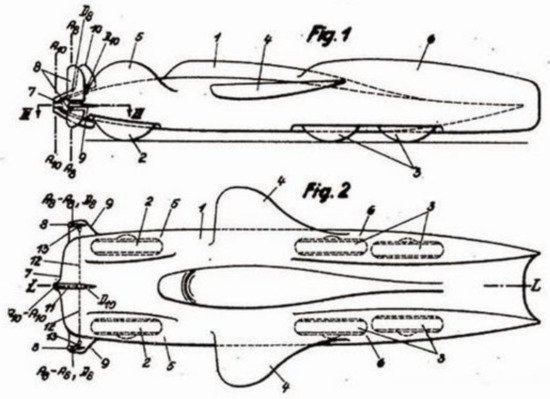
Figure 1. Mercedes T80.
The 1928 Opel RAK2 (Figure 2) rocket-propelled vehicle used large additional wings set at a negative angle to realize downforce on the road to stabilize its movement at high speed. The car set a new land speed record of 148 mph (238 km/h) [4]. The 1952 Mercedes-Benz 300 SL Prototipo race car (Figure 3) was equipped with a manually operated air brake mounted on the roof which could be adjusted to a vertical or horizontal position, when it needed to be actuated or not.
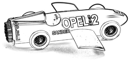
Figure 2. Opel RAK2 rocket-propelled vehicle.
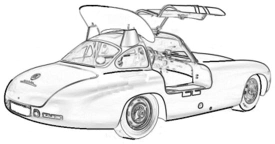
Figure 3. Mercedes-Benz 300 SL Prototipo.
The Mercedes-Benz 300 race cars, equipped with huge drum brakes hidden inside the body connected to the wheels by shafts with joints, were prone to overheating, which caused great maintenance problems. Therefore, engineers mounted a large aerodynamic brake, in the form of a hydraulically raised rear body cover, during test drives (Figure 4). The solution was very effective and was patented [5]. Recently performed numerical calculations [6] revealed an increase by 0.40 in the drag coefficient and aerodynamic downforce caused by the application of the aerodynamic brake. Experimental data [7] indicated an even higher drag coefficient (0.65). The application of the aerodynamic brake increased the frontal area of the car by 24% [8] and the aerodynamic brake had a significant effect only on the vertical load on the rear axle of the car [8][9].
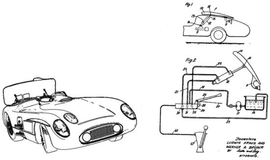
Figure 4. Mercedes-Benz 300 race car with active airbrake and patent drawing [5].
In 1956, Michael May, a talented Swiss enthusiast, used his aerodynamics knowledge and engineering skills to make modifications to his 550 Spyder race car [10]. His Porsche 550 roadster (Figure 5) was fitted with a movable wing over the open cockpit. Winged race cars had been tried before, but the adjustable device on May’s 550 Spyder transferred loads directly to the car’s center of gravity. With better grip, Michael May and his private car achieved fourth lap time during practice for the 1000 km race at the Nürburgring in 1956.
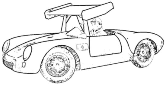
Figure 5. Michael May’s Porsche 550 Spyder car with movable wing.
Porsche formally forced the organizers to acknowledge the alleged safety impact of the May device, namely, that it would obstruct the view of those coming from behind. However, the real reason was different. The modifications introduced made May’s 550 Spyder significantly faster than other 1500 cc cars. The solution was so effective that it became a threat to the Porsche factory team and was forgotten for many years.
Jim Hall built the Chaparral 2C model [11] with a large movable tailgate operated by the driver pressing an extra pedal with his left foot (Figure 6). This was possible due to the semi-automatic transmission used in this car. The integrated spoiler-wing was designed to lie flat to provide low drag on straights and to rise during braking while cornering. The aerodynamic solution was so effective that it overloaded the vehicle’s suspension and made the ride very unpleasant for the driver.
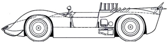
Figure 6. Chaparral 2C with a large movable tailgate.
Therefore, the Chaparral 2F car used a large wing with a variable angle of attack (Figure 7), placed high above the body, from which aerodynamic forces were transferred not to the body but directly to the rear wheel bearing housings of the vehicle [12].
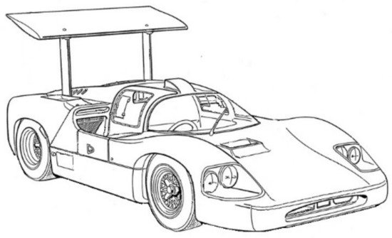
Figure 7. Chaparral 2F.
The Porsche 908 25 series cars were equipped with movable flaps whose movement was mechanically coupled to the movement of the rear wheel suspension.
Another example of a race car with active aerodynamics was the 1968 Porsche 908 LH, which featured two flaps at the rear of the car directly connected to the suspension. Porsche automated the control of the moving flaps by linking their movement to the movement of the body relative to the ground [13]. Deflection of the suspension changed the angle of the flaps.
Linking suspension deflection to the flap angle caused the flap to lift when the car braked, increasing aerodynamic drag and downforce. When cornering, body roll caused activation of the corresponding flap, generating an aerodynamic righting moment. The response of the flaps during climbing and descending was also important. The active elements moved independently of the driver.
This type of movable flap activated by suspension movements was used in the first series of the Porsche 917 [14], a 1969 model (Figure 8) approved for public roads. The flaps were located at the rear edge of the body. This solution was used until being banned by racing regulations.
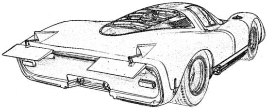
Figure 8. Porsche 917 with movable flaps and mechanism automatically responding to suspension movements.
The retractable spoiler on the Mercedes-Benz C112, extending beyond the rear edge of the vehicle, is another example of the effectiveness of the moving aerodynamic technique (Figure 9).
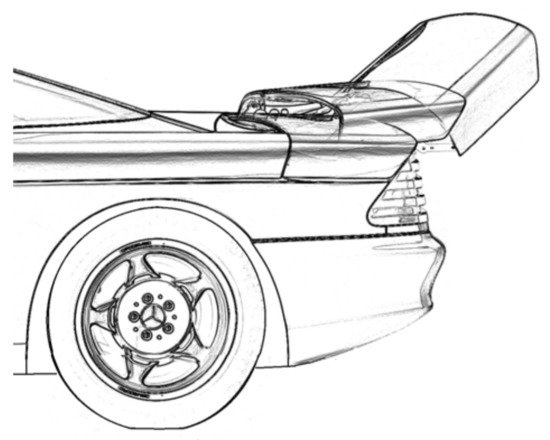
Figure 9. Rear extendable spoiler of the Mercedes-Benz C112.
Lamar [15] presented, very clearly and vividly, the relationship between the on-track behavior of a fast sports car and its aerodynamic properties. This relationship was also true for the Chaparral 2F car with a movable wing transferring aerodynamic forces directly to the suspension (Figure 10). This idea was patented [12].
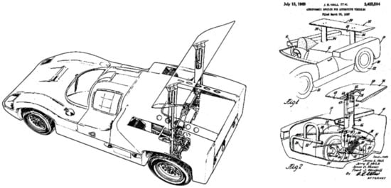
Figure 10. The rear wing of the Chaparral 2F directly transmits the aerodynamic forces to the suspension [12].
The Chaparral 2F car was rated as very stable and pleasant to drive at medium speeds but was found to be very abrupt in its reactions at high speeds [15].
These cars introduced the concept of using a moving wing with an aerodynamic profile to generate downforce, which is still one of the main sources of downforce generated by modern race cars. The goal of this effort was to modify the aerodynamic properties of the vehicle so that it would have low aerodynamic drag on straights at high speeds and a strong downforce in cornering.
The Chaparral cars were included in here because the aerodynamic elements used were active and could be moved to the most favorable position while driving. The position of the wings was controlled by the driver.
Active aerodynamic devices initially used on race cars were designed with limited knowledge of their actual performance. Designers underestimated the increase in vehicle performance while cornering, namely, the increase in inertial forces. The wings were mainly protected from longitudinal forces, rarely from lateral forces. Very often, aerodynamic forces were transferred directly to unsprung suspension components, resulting in the transmission of shocks from the road to the wing nodes. This resulted in frequent failures and consequent crashes. Moving aerodynamic components were banned from racing in the late 1960s. This situation persisted for decades.
The first production model equipped with an active rear spoiler was the 1988 Volkswagen Corrado. At 120 km/h, the rear spoiler is pushed outward, reducing rear lift by up to 64%.
A sophisticated and technically interesting controlled ramp and wing system was used on the Koenigsegg Agera (Figure 11).
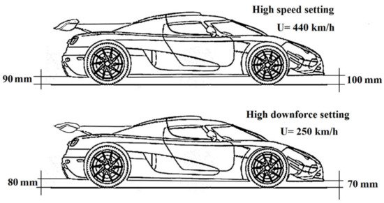
Figure 11. Rear spoiler of Koenigsegg Agera and its modes of operation.
A contemporary example of the use of various possibilities of changing the aerodynamic characteristics of a fast road car is the Bugatti Veyron, which, in addition to moving aerodynamic elements, can change the position of its body relative to the road, and has adjustable ground clearance and adjustable body tilt angle [16]. This is considered the first intelligent aerodynamic management system in the history of automotive design. The rear spoiler acts as an additional aerodynamic brake at speeds above 200 km/h. When the brake pedal is pressed, the spoiler lifts up and deploys at 55° in less than 0.4 s (Figure 12).
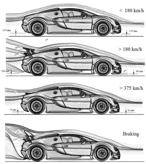
Figure 12. Bugatti Veyron operation modes [16].
References
- Yu, W.; Gao, W. A Review of the influence of active aerodynamic tail on vehicle handling stability. FMIA 2021 J. Phys. Conf. Ser. 2021, 1985, 012017.
- Gao, W.; Kong, X.; Deng, Z.; Yu, W.; Wu, Y.; Luo, J. Review of state of the art in active aerodynamic control research for vehicles. FMIA 2021 J. Phys. Conf. Ser. 2021, 1985, 012040.
- Available online: http://greyfalcon.us/Mercedes%20T80.htm (accessed on 10 October 2021).
- Available online: https://drivemag.com/red-calipers/90-years-ago-opel-built-and-raced-a-rocket-car (accessed on 30 August 2021).
- Ludwig, K.; Bruder, W.A. Aerodynamic Braking Mechanism for Motor Vehicles. US Patent 2932370A, 11 June 1956.
- Falkovén, A.; Nordin, J.; Rama, K.; Rask, A.; Sjöstrand, P.; Stadler, M. CFD-Analysis of the Aerodynamic Properties of a Mercedesmercedes-Benz Benz 300SLR. n.d. Available online: https://publications.lib.chalmers.se/records/fulltext/219318/219318.pdf (accessed on 19 August 2021).
- Schuetz, T.C. Aerodynamics of Road Vehicles, 5th ed.; SAE Inter-National: Warrendale, PA, USA, 2015.
- Gullberg, P.; Löfdahl, L.; Qiu, Z. Influence of aerodynamics on the fatal crash in Le Mans 1955. In Proceedings of the 4th European Automotive Simulation Conference, Munich, Germany, 6–7 July 2009.
- Gullberg, P.; Löfdahl, L. The Role of Aerodynamics in the 1955 Le Mans Crash; SAE International: Warrendale, PA, USA, 2008.
- Available online: https://simanaitissays.com/2016/06/15/porsche-aerodynamics/ (accessed on 10 October 2021).
- Available online: https://en.wikipedia.org/wiki/Chaparral_Cars (accessed on 10 October 2021).
- Hall, J.E.; Mrlik, J.R.; Musser, J.G.; Winchell, F.J. Aerodynamic Spoiler for Automotive Vehicles. US Patent 3455594, 15 July 1969.
- Mezger, H. Der Porsche 4,5-l-Rennsportwagen Typ 917, Teil 2, ATZ, BD; 1969; Volume 71, pp. 417–423. Available online: https://presskit.porsche.de/museum/en/2019/topic/anniversaries/porsche-celebrates-50-years-of-the-917/hans-mezger-the-porsche-917-chief-engineer.html (accessed on 15 September 2021).
- Hucho, W.-H. (Ed.) Aerodynamics of Road Vehicles, 4th ed.; SAE International: Warrendale, PA, USA; Materials Park, OH, USA, 1998; p. 918.
- Lamar, P. Aerodynamics & The Group Seven Racing Car. In Proceedings of the AIAA Symposium on The Aerodynamics of Sports & Competition Automobiles, Los Angeles, CA, USA, 20 April 1968.
- Available online: https://www.bugatti.com/models/veyron-models/technology/ (accessed on 10 October 2021).
More
Information
Subjects:
Engineering, Mechanical
Contributor
MDPI registered users' name will be linked to their SciProfiles pages. To register with us, please refer to https://encyclopedia.pub/register
:
View Times:
4.6K
Revisions:
2 times
(View History)
Update Date:
08 Apr 2022
Table of Contents


Notice
You are not a member of the advisory board for this topic. If you want to update advisory board member profile, please contact office@encyclopedia.pub.
OK
Confirm
Only members of the Encyclopedia advisory board for this topic are allowed to note entries. Would you like to become an advisory board member of the Encyclopedia?
Yes
No
${ textCharacter }/${ maxCharacter }
Submit
Cancel
Back
Comments
${ item }
|
${ item.createdUser.fullName }
${ item.createdAt }
${ item.vote }
${ item.reply }
Delete
${ reply.createdUser.fullName }
${ reply.createdAt }
${ reply.vote }
Delete
There is no reply to this comment~
${ item.replyTextCharacter }/${ item.replyMaxCharacter }
Submit
Cancel
More
No more~
There is no comment~
${ textCharacter }/${ maxCharacter }
Submit
Cancel
${ selectedItem.replyTextCharacter }/${ selectedItem.replyMaxCharacter }
Submit
Cancel
Confirm
Are you sure to Delete?
Yes
No