Your browser does not fully support modern features. Please upgrade for a smoother experience.
Submitted Successfully!
 +1 credit
Thank you for your contribution! You can also upload a video entry or images related to this topic.
For video creation, please contact our Academic Video Service.
| Version | Summary | Created by | Modification | Content Size | Created at | Operation |
|---|---|---|---|---|---|---|
| 1 | Xingxing Wang | + 3371 word(s) | 3371 | 2022-03-15 08:55:53 | | | |
| 2 | Rita Xu | Meta information modification | 3371 | 2022-03-23 04:46:49 | | | | |
| 3 | Lindsay Dong | Meta information modification | 3371 | 2022-03-28 07:16:11 | | |
Video Upload Options
We provide professional Academic Video Service to translate complex research into visually appealing presentations. Would you like to try it?
Cite
If you have any further questions, please contact Encyclopedia Editorial Office.
Wang, X. Power Battery Thermal Management System. Encyclopedia. Available online: https://encyclopedia.pub/entry/20863 (accessed on 10 June 2026).
Wang X. Power Battery Thermal Management System. Encyclopedia. Available at: https://encyclopedia.pub/entry/20863. Accessed June 10, 2026.
Wang, Xingxing. "Power Battery Thermal Management System" Encyclopedia, https://encyclopedia.pub/entry/20863 (accessed June 10, 2026).
Wang, X. (2022, March 22). Power Battery Thermal Management System. In Encyclopedia. https://encyclopedia.pub/entry/20863
Wang, Xingxing. "Power Battery Thermal Management System." Encyclopedia. Web. 22 March, 2022.
Copy Citation
The battery thermal management system is a key skill that has been widely used in power battery cooling and preheating. It can ensure that the power battery operates safely and stably at a suitable temperature.
power battery
thermal management system
cooling system
1. Introduction
New energy vehicles have the advantages of less pollution and low emissions. To alleviate a series of problems such as global temperature warming and energy depletion, the use of new energy can not only reduce greenhouse gas emissions by about 20% but also significantly reduce the use of non-renewable energy compared with traditional fuel vehicles. With these advantages, new energy vehicles have attracted much attention in various countries in recent years [1][2]. With the continuous improvement of people’s awareness of new energy vehicles, their possession is also increasing year by year, more and more favored by people, but a series of failures related to power batteries are also known to people, so it is urgent to seek relevant solutions. The temperature has a great impact on battery performance, battery life, and battery safety. When the temperature is too low or too high, the power battery may have thermal runaway, capacity decline, internal resistance increase, life attenuation, and charging and discharging difficulties [3][4]. Therefore, it is necessary to develop a complete, efficient and reliable battery management system to ensure the safety and smooth operation of power batteries. As an important part of the battery management system, the battery thermal management system plays a significant role in dealing with the battery thermal-related problems and ensuring the performance, safety, and life of the power battery [5].
2. Cooling System
The safe working range of the power battery is generally about −40 °C to 60 °C, and the best working range is generally between 15 °C to 35 °C [6][7], and the temperature difference should be kept within 5 °C [8][9]. When the temperature is too high, the battery working environment may exceed the scope of its work safety, so that the power battery respect to the failure of large area, the thermal runaway phenomenon occurring, serious when a battery or spontaneous combustion explosion, to make the battery working temperature control within the scope of the safety or the best work, for heat dissipation of the battery is necessary.
2.1. Air Cooling System
Air cooling systems can be divided into natural convection cooling systems and forced convection cooling systems, which use the natural convection of external air or forced convection of air by mechanical devices so that the external cold air flows through the surface of each cell of the power battery to conduct heat exchange to achieve the purpose of cooling. Air cooling systems have the simplest structure among all cooling systems and low manufacturing cost, but it also has the defects of a poor cooling effect and slow cooling speed [10][11], which cause the heat dissipation requirements of electric vehicle battery modules not to be well-met present. In recent years, research on air-cooled heat dissipation systems has mainly focused on the arrangement of single components in battery modules, new ventilation forms, and optimization of air channel structures. According to different ventilation modes, the air-cooling battery management system can be divided into serial air supply mode and parallel air supply model [12]. Figure 1 is a schematic diagram of the structure of serial air supply and parallel air supply.
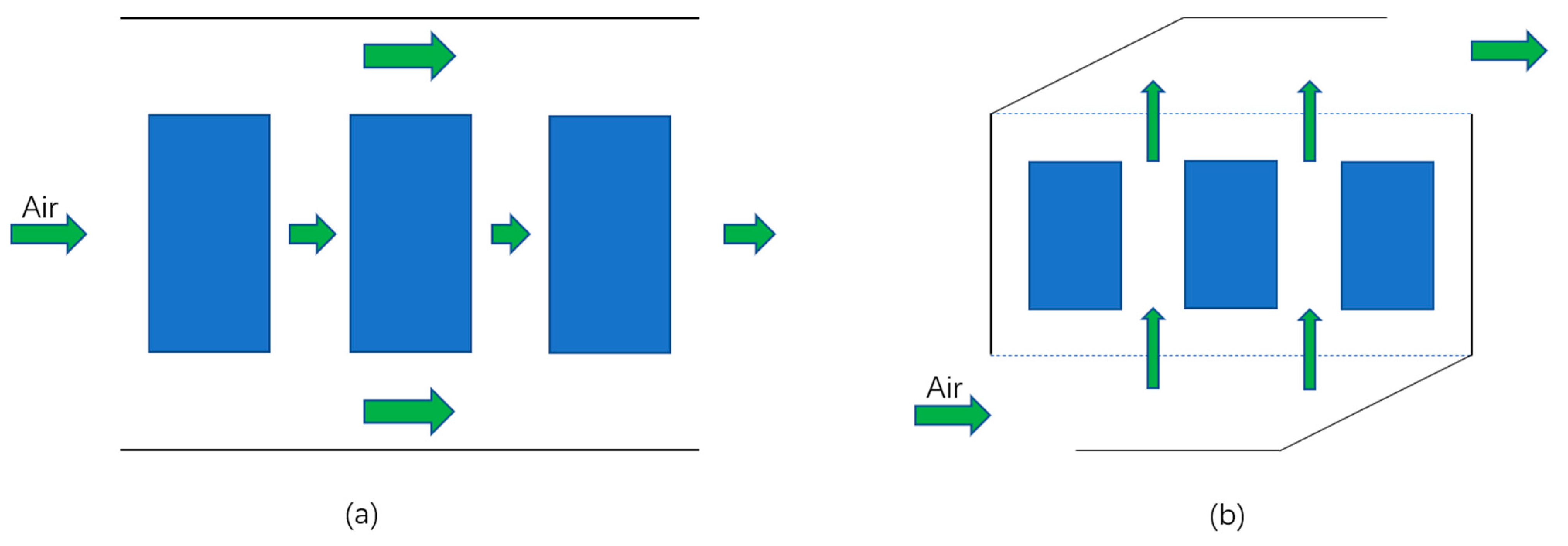
Figure 1. The schematic diagram of the air supply mode of the air-cooling system, (a) the serial air supply, (b) the parallel air supply.
When ventilating in series, the air enters the ventilation duct and flows over the surface of the battery in turn, during the flow, the temperature of the air gradually increases, and the temperature difference between the air and the battery continues to shrink, resulting in the uneven temperature of the battery pack. The temperature and flow rate of the upstream and downstream are different. The upstream cell is close to the air inlet, the flow rate is high, and the temperature is low. The downstream battery is close to the air outlet, and the heat transfer efficiency of the downstream battery surface decreases, and the temperature is high. Therefore, the temperature consistency of the battery module is poor. In parallel ventilation, the air flows through the battery surface at the same time, the air velocity and airflow through the battery surface are relatively uniform, the heat exchange conditions of each battery surface are almost the same, and the temperature uniformity of the battery module is improved, Therefore, the air-cooled battery the heat dissipation method of parallel ventilation in the thermal management system is widely used. Zhang et al. [13] found that adding a spoiler in the cooling channel of the battery pack can further improve the cooling performance and temperature uniformity of the battery, the experimental results show that compared with the battery without spoilers, the maximum temperature and the maximum temperature difference of the battery pack are dropped by 1.86 °C and 2.51 °C. Pan et al. [14] studied a method of adding fans in parallel ventilation mode to improve the uniformity of battery pack temperature. The experiment found that adding a fan in the air inlet duct can effectively improve the uniformity of the gas flow of the battery module. When the flow rate of the cooling air at the inlet is greater than 7 m/s, the average temperature difference of the battery pack is maintained at about 1.4 °C. Li et al. [15] Studied the effects of battery arrangement, battery spacing and air velocity at the air inlet on the temperature field distribution of serial 18650 cylindrical lithium-ion battery pack. The experimental results show that when the battery spacing is 4 mm and the wind speed is 4 m/s, the battery pack is arranged in sequence to obtain the best cooling effect under the condition of ensuring the consistency of other parameters. Xu et al. [16] studied the heat dissipation performance of ventilation ducts at the bottom of different battery packs under forced air convection cooling. Through four working conditions of continuous acceleration, continuous deceleration, shelving, pulse discharge, and vehicle operation, the temperature rise and internal temperature difference at the bottom of different battery packs using double “U” type air ducts and double “I” type air ducts are simulated and analyzed. The experimental comparison results show that the temperature rise and internal temperature difference of double “U” type air ducts are lower than that of double “I” type air ducts, and the temperature difference of battery pack can be controlled at about 3 °C. Yuan et al. [17] studied a new type of air-cooling system with a z-shaped structure, and reduced the maximum temperature, temperature difference, and non-uniformity of the battery pack by adjusting the deflector plate and round chamfer. The experimental results found that when the deflection angle is 60°, when the round chamfer is 5mm, the cooling performance of the battery pack is the best, and the maximum temperature can be reduced by 2.52 °C, the temperature difference and unevenness can be reduced by 366.66% and 36.50%.
2.2. Liquid Cooling System
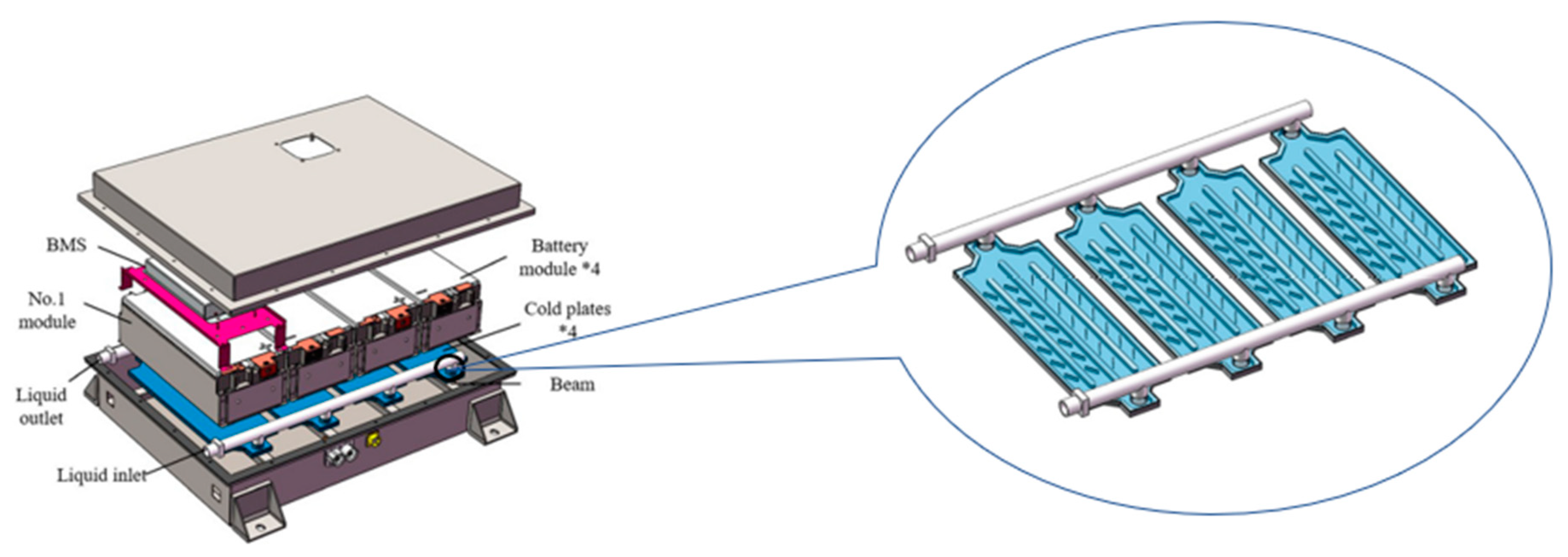
A liquid cooling system refers to a thermal management system in which the cooling liquid directly or indirectly contacts the power battery module, and then the heat generated by the power battery is taken away in time through the continuous circulation of the cooling liquid. The liquid cooling system can be divided into direct contact and indirect contact according to the contact mode between the coolant and the battery, the direct contact mode requires coolant insulation. Compared with the air-cooled heat dissipation system, the liquid cooling system generally has a higher heat dissipation capacity and a more obvious cooling effect. However, it requires external components such as pumps and heat exchangers, which not only makes the structure more complex and increases the cost of production, maintenance, and maintenance but also causes secondary losses when the battery has to supply power to external components. Although the liquid cooling and heat management system has been quite perfect and mature and is widely used in the heat dissipation system of new energy vehicles, there is still a lot of room for development. At present, the research and development of the liquid-cooling heat dissipation system of electric vehicles at home and abroad focus on the optimization of the cooling medium runner structure and the expansion of the contact area between the cold plate and the battery module. In order to compare the thermal management performance of the small cooling channel and the larger cooling channel, Yates M et al. [18] conducted a study under the condition of a discharge rate of 5 C and an ambient air temperature of 24.85 °C. Under this circumstance, the maximum temperature of the two designs can be controlled below 34.85 °C, and the temperature difference can be controlled within 3.15 °C. The maximum temperature of the battery pack using the small cooling channel is lower than the maximum temperature of the battery pack using the larger cooling channel, but the temperature has Poor consistency and high cost. Propane is often used as a coolant because of its stable chemical properties and no chemical reaction. Al-Zareer et al. [19] use propane as a cooling medium by comparing the influence of the spacing between batteries on thermal management. Simulation results show that reducing the spacing between batteries will improve the maximum temperature of the battery, but it can improve the temperature consistency of the battery; the larger cell spacing reduces the maximum temperature of the cells, but also increases the temperature difference between the cells. Tang et al. [20] studied the method of adding fins to the liquid cooling plate to improve the cooling efficiency of the thermal management system, established a liquid-cooled battery system model, and studied the heat balance performance of the parallel liquid cooling system through numerical analysis. Its position structure is shown in Figure 2. The research results show that the optimized parallel liquid cooling system can keep the maximum temperature of the battery system below 44.31 °C, and the temperature difference of the battery system is within 3 °C, which meets the temperature requirements of the power battery system.
Rao et al. [21] to keep the maximum temperature and local temperature difference of columnar battery in an appropriate range, proposed a columnar battery cooling method based on a microchannel liquid cooling cylinder. The effects of the number of channels, mass flow rate, flow direction, and inlet size on the heat dissipation performance of pipes were studied numerically. The results show that when the number of small channels is not less than 4 and the inlet mass flow rate is 1103 kg/s, the maximum temperature of 42,110 cylindrical batteries can be controlled below 40 °C. Considering both the maximum temperature and local temperature difference, only when the number of channels is greater than 8, the cooling mode of the liquid cooling cylinder can show greater advantages than natural convection cooling. The ability to reduce the maximum temperature by increasing the mass flow rate is limited. When the inlet mass flow rate is constant, the heat dissipation capacity increases first and then decreases with the increase of the inlet size. Min et al. [22] established a liquid-cooled battery module based on the micro-channel wavy flat tube for heat dissipation of cylindrical power battery, the results showed that increasing the contact angle of the wavy flat-tube could improve the heat dissipation efficiency of the liquid-cooled structure and improve the uniformity of temperature distribution of battery pack. Pan et al. [23] designed a parallel multi-channel liquid cooling plate, established a three-dimensional thermal model of the battery module and the liquid cooling plate and analyzed the effects of the thickness of the cooling plate, the thickness of the cooling pipe, the number of channels and the coolant mass flow on the cooling performance of the battery module after the influence, the four factors were optimized by orthogonal experiments, and the optimized results showed that the maximum temperature control and temperature uniformity of the liquid-cooled battery module was significantly enhanced.
2.3. Phase Change Material Cooling System
The phase-change material cooling system uses phase change material as a heat transfer medium, which can store energy and release energy during the phase change, to achieve the effect of low-temperature heating and high-temperature heat dissipation of the power battery. According to the form of phase-change material, it can be divided into solid-solid phase-change materials, solid-liquid phase-change materials, solid-gas phase-change materials, and liquid-phase-change materials. At present, the focus of industry research is mainly on solid-solid phase-change materials and solid-liquid phase-change materials on the material. The phase-change material heat dissipation system has the advantages of relatively simple system design and low cost, but the thermal conductivity of the current phase-change material is still relatively low, resulting in a low heat dissipation rate, so it is not particularly widely used in new energy vehicles. Due to the low thermal conductivity of phase-change materials, at present, the main effort is to add a highly conductive matrix to the structure of the phase-change material to increase its thermal conductivity and optimize the arrangement. Temel et al. [24] added graphene nanoplatelets (graphene nanoplatelets, GNP) with different mass fractions into phase change materials to study the instantaneous thermal response of composites in energy storage units. The results show that the thermal conductivity of the composite increases linearly with the increase of the GNP mass fraction, and the temperature difference in the energy storage unit decreases significantly. When the mass fraction of GNP is 7%, the thermal conductivity increases by 253%, and the effective utilization time of the energy storage unit is prolonged by 32 min. A. Babapoor et al. [25] increased the thermal conductivity of the phase-change material by adding carbon fiber to the phase-change material. The results show that the presence of carbon fiber increases the thermal conductivity of the phase-change material, thereby affecting the temperature distribution inside the battery, and the carbon fiber content the higher the phase-change material, the more uniform the temperature distribution. The distribution of the effect of carbon fiber content on the battery temperature is shown in Figure 3.
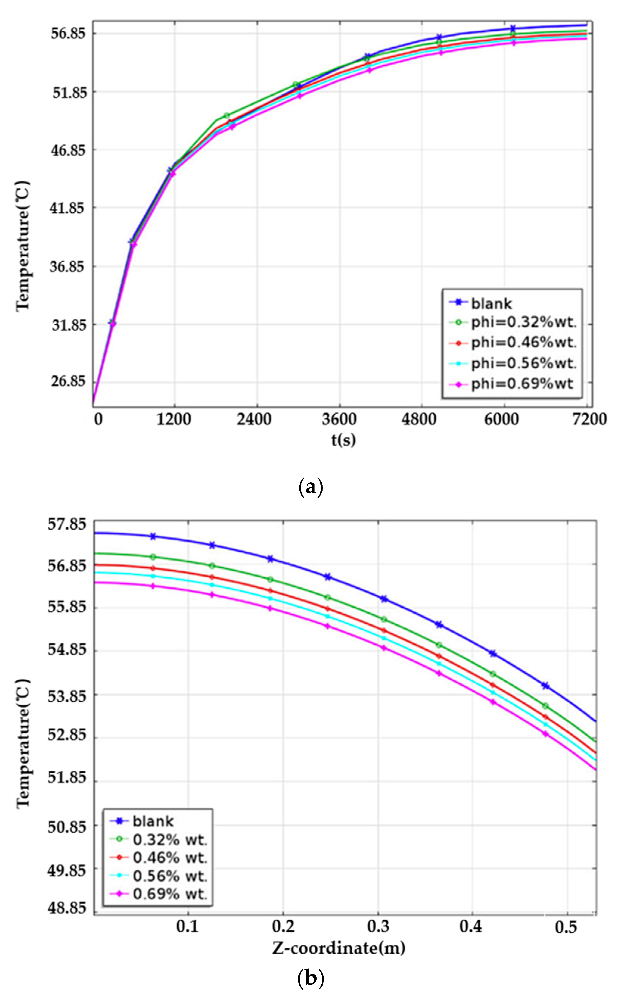
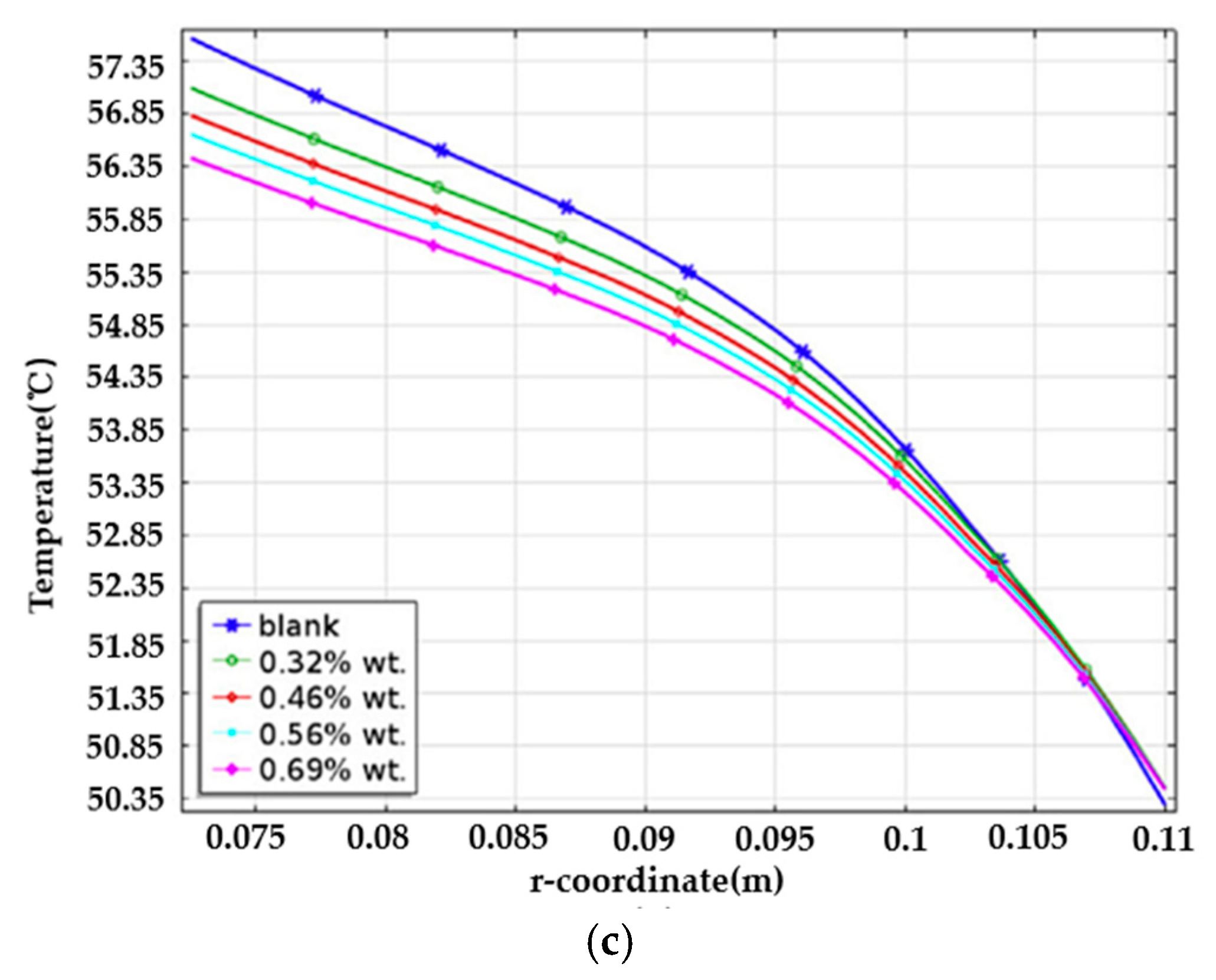
Figure 3. The effect of different carbon fiber loadings on the battery: (a) the change of the battery surface temperature with time; (b) the change of the battery surface temperature with the height; (c) the change of the radial battery temperature [25]. Reproduced from reference [25] with permission from Elsevier B.V., copyright 2016.
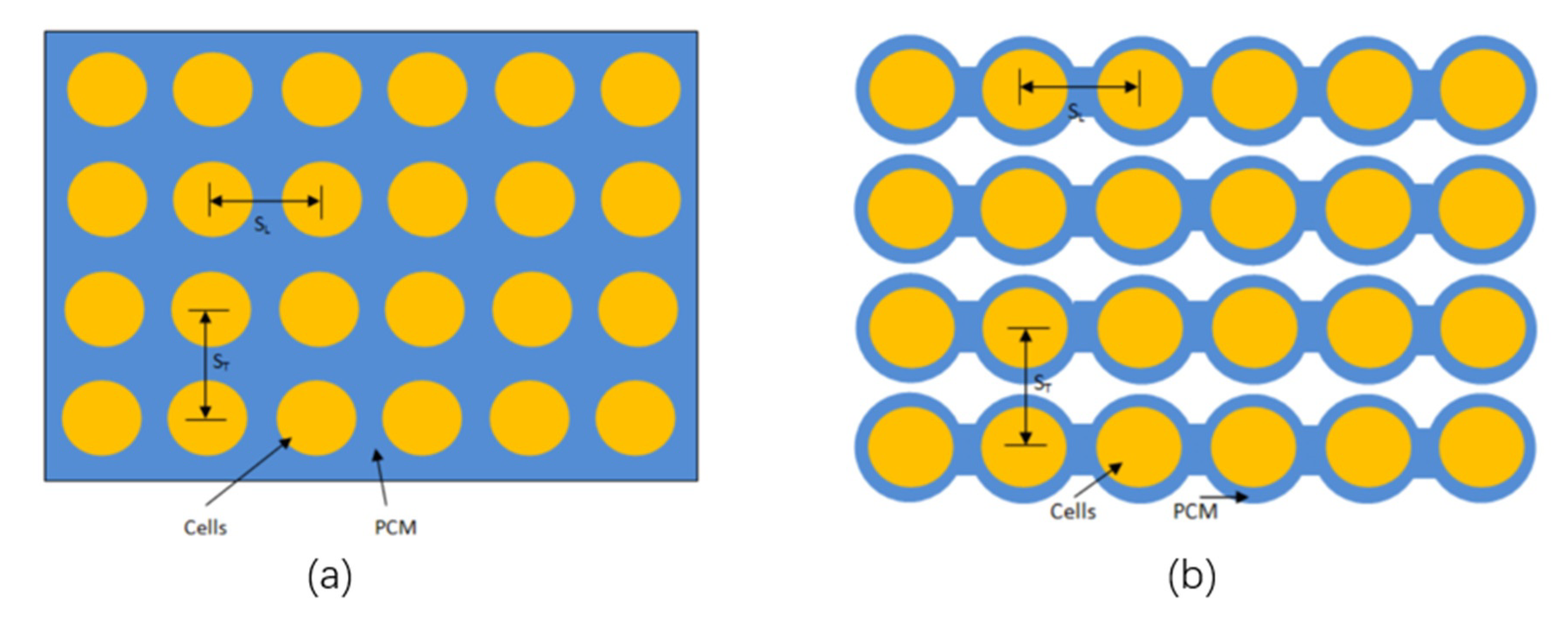
Adding high thermal conductivity metal to the phase-change material or using foam metal to adsorb the phase-change material, the obtained composite phase-change material system also has a good thermal management effect. Wang et al. [26] used foamed copper/phase-change materials to thermally manage different types of lithium-ion batteries and compared the effects of phase-change materials and natural air convection in an insulating environment. The temperature control effect of the phase-change material is better than that of air convection, and the maximum temperature of 26,650, 42,110 and square batteries can be controlled below 44.37 °C, 51.45 °C and 50.69 °C for a longer time. In contrast to this, Jilte et al. [27] analyzed the arrangement of traditional battery cells and phase-change materials and reduced the thickness of phase-change materials between battery cells to discharge heat into the voids faster and improve battery performance. For heat dissipation efficiency, the study found that a 4 cm thickness of the phase-change material around the battery cell is sufficient for heat dissipation. When the ambient temperature is 35 °C and the discharge rate is 5 C after the discharge cycle is over, the maximum temperature of the battery is controlled at 41 °C, and the maximum temperature difference between the battery cells is controlled at 0.05 °C. As shown in Figure 4, the left is the traditional rectangular PCM-filled battery pack, and the right is the improved PCM-filled battery pack.
2.4. Heat Pipe Cooling System
Heat pipe cooling technology was first applied in the aerospace industry and military industry. The essence of heat transfer is the phase change reaction of the working medium in the tube. Heat can be rapidly transferred from the heat source through a heat pipe, and this thermal conductivity exceeds all the known metals at present. Due to the immaturity of pipes, production standards, production equipment, etc., the application in thermal management of power batteries is mostly in the research stage and has not been popularized and used. Tian et al. [28] designed a heat pipe-aluminum plate heat dissipation module for lithium-ion batteries, which increased the contact area between the heat pipe and the battery and enhanced heat exchange. Through numerical simulation and orthogonal experiment Analytic Hierarchy Process (AHP), the influence degree and weight of each factor on the cooling performance of the module are studied, and the parameters are optimized. The experimental results show that under each experimental scheme, the temperature difference of the battery module is controlled within 3 °C, indicating that the temperature uniformity of the battery module using this heat dissipation has been enhanced. Dan [29] studied a battery thermal management system based on a Micro heat pipe array (MHPA), the schematic diagram of the structure of the micro heat pipe array is shown in Figure 5.
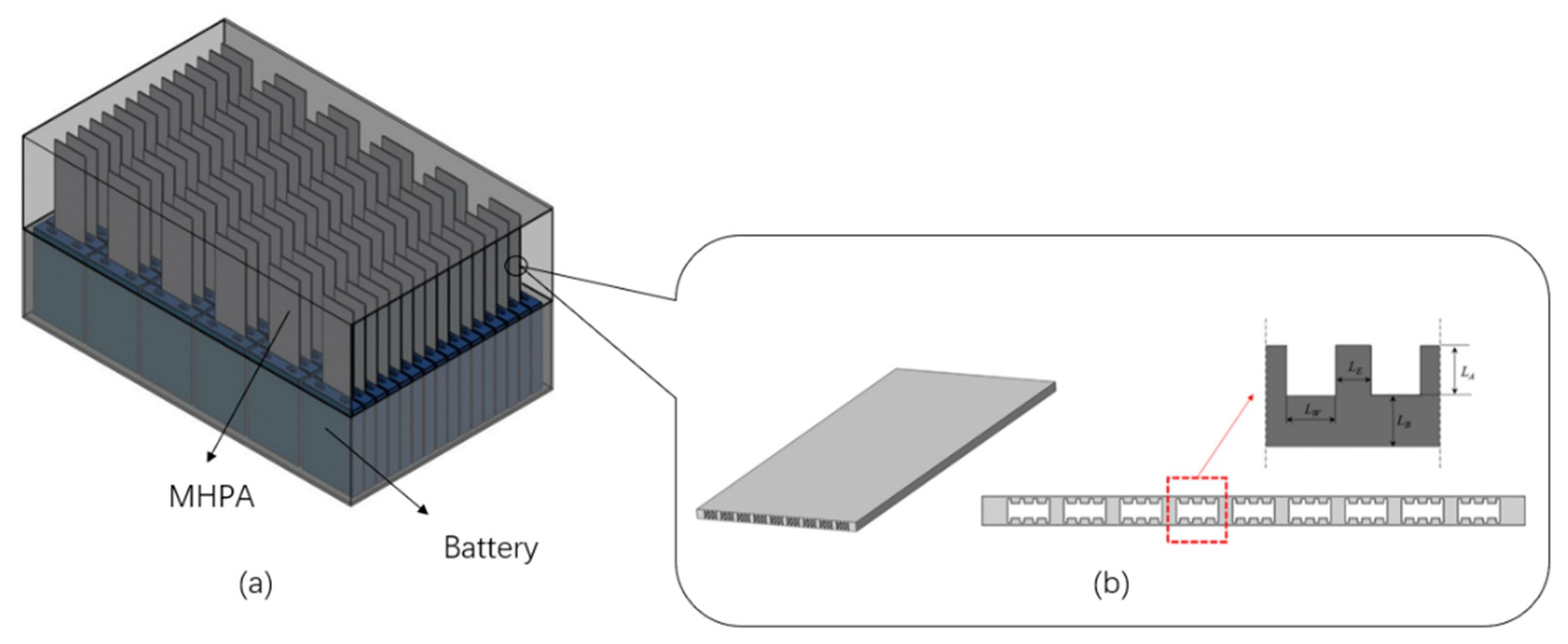
Figure 5. Schematic diagram of the thermal management system of the micro heat pipe array (a) the schematic diagram of the combination of the micro heat pipe array and the battery, (b) the schematic diagram of the MHPA structure [29]. Reproduced from reference [29] with permission from Elsevier B.V., copyright 2019.
At the rate of 3 m/s in forced airflow, simulation analysis of the single battery module and a single equipped with battery module of micro heat pipe array thermal performance, and on the basis of the comparison, found in forced to shed, single battery module temperature is 41.2 °C, and equipped with micro heat pipe array of single battery module temperature is 36.1 °C, when a sudden increase or decrease in the charging rate, behave more moderate heat pipe cooling system, it has very good cooling efficiency, and is made up of 96 battery monomer battery pack to simulate the temperature changes within the battery pack and distribution situation, the study found that the heat pipe cooling system is better than that of forced air convection on the temperature control system, at the end of the discharge, battery control within 40 °C, the highest temperature the maximum temperature difference is only 2.04 °C, the simulation results show that the battery pack equipped with heat pipe can significantly improve the temperature uniformity. To obtain the influence of the liquid filling rate and heat flow density on heat pipe heat transfer performance, Nandy Putra et al. [30] conducted an experimental study using a flat plate loop heat pipe (FPLHP) as a heat exchanger for the thermal management system of an electric vehicle lithium-ion battery. They simulated the heat generation process of the battery by using a cylinder heater, and adopted stainless steel sieve for the capillary core, the working liquid is distilled water, alcohol, and acetone, and the filling ratio is 60%. The experimental results show that the flat circular heat pipe has certain application potential in the thermal management system of lithium-ion batteries. In addition to the heat pipe heat transfer with high thermal conductivity, excellent isothermal property, heat flow density variable, and the advantages of the reversible heat flow direction, and heat pipe cooling way very easily with other coupling is used, such as heat pipe air cooling, heat pipe cooling, heat pipe - liquid cooling phase-change materials, etc., in short, heat pipe cooling system has very good prospects for development. The advantages and disadvantages of the four cooling systems are shown in Table 1.
Table 1. Features of the four cooling systems.
| Serial Number | Cooling System | Advantage | Shortcoming |
|---|---|---|---|
| 1 | Air cooling system | Simple structure, low cost, small footprint, lightweight, etc. | Low thermal conductivity, poor cell uniformity control, etc. |
| 2 | Liquid cooling system | Good thermal conductivity, good cooling effect, relatively uniform heat dissipation, etc. | There is a risk of liquid leakage, difficult maintenance, heavyweight, complex structure, etc. |
| 3 | Phase-change material cooling system | High heat density, large latent heat, good stability, fast heat dissipation, high-temperature control uniformity, etc. | The heat absorbed by the phase change material cannot be well dissipated to the external environment, etc. |
| 4 | Heat pipe cooling system | High thermal conductivity, high heat dissipation efficiency, fast heating rate, good uniform performance, good safety, high reliability, etc. | High cost, difficult to control the amount of heat exchange medium, complicated structure, inconvenient installation, etc. |
References
- Andersen, P.H.; Mathews, J.A.; Rask, M. Integrating private transport into renewable energy policy: The strategy of creating intelligent recharging grids for electric vehicles. Energy Policy 2009, 37, 2481–2486.
- Teixeira AC, R.; Sodré, J.R. Impacts of replacement of engine powered vehicles by electric vehicles on energy consumption and CO2 emissions. Transp. Res. D Transp. Environ. 2018, 59, 375–384.
- Wang, Q.; Ping, P.; Zhao, X.; Chu, G.; Sun, J.; Chen, C. Thermal runaway caused fire and explosion of lithium-ion battery. J. Power Sources 2012, 208, 210–224.
- Spitthoff, L.; Shearing, P.R.; Burheim, O.S. Temperature, Ageing and Thermal Management of Lithium-Ion Batteries. Energies 2021, 14, 1248.
- Yang, S.; Ling, C.; Fan, Y.; Yang, Y.; Tan, X.; Dong, H. A review of lithium-ion battery thermal management system strategies and the evaluate criteria. Int. J. Electrochem. Sci. 2019, 14, 6077–6107.
- Goutam, S.; Timmermans, J.M.; Omar, N.; Bossche, P.V.D.; Van Mierlo, J. Comparative study of surface temperature behavior of commercial li-ion pouch cells of different chemistries and capacities by infrared thermography. Energies 2015, 8, 8175–8192.
- Rugh, J.P.; Pesaran, A.; Smith, K. Electric Vehicle Battery Thermal Issues and Thermal Management Techniques (Presentation); National Renewable Energy Laboratory (NREL): Golden, CO, USA, 2013.
- Saw, L.H.; Poon, H.M.; San Thiam, H.; Cai, Z.; Chong, W.T.; Pambudi, N.A.; King, Y.J. Novel thermal management system using mist cooling for lithium-ion battery packs. Appl. Energy 2018, 223, 146–158.
- Aris, A.M.; Shabani, B. An experimental study of a lithium ion cell operation at low temperature conditions. Energy Procedia 2017, 110, 128–135.
- Yang, T.; Yang, N.; Zhang, X.; Li, G. Investigation of the thermal performance of axial-flow air cooling for the lithium-ion battery pack. Int. J. Therm. Sci. 2016, 108, 132–144.
- Na, X.; Kang, H.; Wang, T.; Wang, Y. Reverse layered air flow for Li-ion battery thermal management. Appl. Therm. Eng. 2018, 143, 257–262.
- Ikezoe, M.; Hirata, N.; Amemiya, C.; Miyamoto, T.; Watanabe, Y.; Hirai, T.; Sasaki, T. Development of High Capacity Lithium-Ion Battery for Nissan Leaf; SAE Technical Paper; SAE International: Warrendale, PA, USA, 2012.
- Zhang, F.; Lin, A.; Wang, P.; Liu, P. Optimization design of a parallel air-cooled battery thermal management system with spoilers. Appl. Therm. Eng. 2021, 182, 116062.
- Pan, S.; Ji, C.; Wang, S.; Wang, B. Study on the performance of parallel air-cooled structure and optimized design for lithium-ion battery module. Fire Technol. 2020, 56, 2623–2647.
- Li, K.; Tan, X.; Chu, Y.; Fan, Y. A research on the air cooling thermal management system of lithium-ion traction battery pack in electric vehicles. J. Chin. J. Power Sources 2019, 43, 1975–1978, 2035.
- Xiaoming, X.; Wei, T.; Jiaqi, F.; Donghai, H.; Xudong, S. The forced air cooling heat dissipation performance of different battery pack bottom duct. Int. J. Energy Res. 2018, 42, 3823–3836.
- Xi, Y.; Feng, Y.; Xiao, Y.; He, G. Novel Z-shaped structure of lithium-ion battery packs and optimization for thermal management. J. Energy Eng. 2020, 146, 04019035.
- Yates, M.; Akrami, M.; Javadi, A.A. Analysing the performance of liquid cooling designs in cylindrical lithium-ion batteries. J. Energy Storage 2021, 33, 100913.
- Al-Zareer, M.; Dincer, I.; Rosen, M.A. A novel approach for performance improvement of liquid to vapor based battery cooling systems. Energy Convers. Manag. 2019, 187, 191–204.
- Tang, W.; Ding, H.; Xu, X.; Fu, J.; Liu, L.; Wei, W.; Xiao, Y.; Huang, H. Research on battery liquid-cooled system based on the parallel connection of cold plates. J. Renew. Sustain. Energy 2020, 12, 045701.
- Zhao, J.; Rao, Z.; Li, Y. Thermal performance of mini-channel liquid cooled cylinder based battery thermal management for cylindrical lithium-ion power battery. Energy Convers. Manag. 2015, 103, 157–165.
- Min, X.; Tang, Z.; Gao, Q.; Song, A.; Wang, S. Heat dissipation characteristic of liquid cooling cylindrical battery module based on mini-channel wavy tube. J. Zhejiang Univ. 2019, 53, 463–469.
- Pan, C.; Tang, Q.; He, Z.; Wang, L.; Chen, L. Structure optimization of battery module with a parallel multi-channel liquid cooling plate based on orthogonal test. J. Electrochem. Energy Convers. Storage 2020, 17, 021104.
- Temel, U.N.; Somek, K.; Parlak, M.; Yapici, K. Transient thermal response of phase change material embedded with graphene nanoplatelets in an energy storage unit. J. Therm. Anal. Calorim. 2018, 133, 907–918.
- Samimi, F.; Babapoor, A.; Azizi, M.; Karimi, G. Thermal management analysis of a Li-ion battery cell using phase change material loaded with carbon fibers. Energy 2016, 96, 355–371.
- Wang, Z.; Li, X.; Zhang, G.; Lv, Y.; He, J.; Luo, J.; Yang, C.; Yang, C. Experimental study of a passive thermal management system for three types of battery using copper foam saturated with phase change materials. RSC Adv. 2017, 7, 27441–27448.
- Jilte, R.D.; Kumar, R.; Ahmadi, M.H.; Chen, L. Battery thermal management system employing phase change material with cell-to-cell air cooling. Appl. Therm. Eng. 2019, 161, 114199.
- Tian, S.; Xiao, J. Numerical simulation and analysis of lithium-ion battery heat pipe cooling module based on orthogonal analytic hierarchy process. CIESC J. 2020, 71, 3510–3517.
- Dan, D.; Yao, C.; Zhang, Y.; Zhang, H.; Zeng, Z.; Xu, X. Dynamic thermal behavior of micro heat pipe array-air cooling battery thermal management system based on thermal network model. Appl. Therm. Eng. 2019, 162, 114183.
- Putra, N.; Ariantara, B.; Pamungkas, R.A. Experimental investigation on performance of lithium-ion battery thermal management system using flat plate loop heat pipe for electric vehicle application. Appl. Therm. Eng. 2016, 99, 784–789.
More
Information
Subjects:
Energy & Fuels
Contributor
MDPI registered users' name will be linked to their SciProfiles pages. To register with us, please refer to https://encyclopedia.pub/register
:
View Times:
1.8K
Revisions:
3 times
(View History)
Update Date:
28 Mar 2022
Table of Contents


Notice
You are not a member of the advisory board for this topic. If you want to update advisory board member profile, please contact office@encyclopedia.pub.
OK
Confirm
Only members of the Encyclopedia advisory board for this topic are allowed to note entries. Would you like to become an advisory board member of the Encyclopedia?
Yes
No
${ textCharacter }/${ maxCharacter }
Submit
Cancel
Back
Comments
${ item }
|
${ item.createdUser.fullName }
${ item.createdAt }
${ item.vote }
${ item.reply }
Delete
${ reply.createdUser.fullName }
${ reply.createdAt }
${ reply.vote }
Delete
There is no reply to this comment~
${ item.replyTextCharacter }/${ item.replyMaxCharacter }
Submit
Cancel
More
No more~
There is no comment~
${ textCharacter }/${ maxCharacter }
Submit
Cancel
${ selectedItem.replyTextCharacter }/${ selectedItem.replyMaxCharacter }
Submit
Cancel
Confirm
Are you sure to Delete?
Yes
No