Your browser does not fully support modern features. Please upgrade for a smoother experience.
Submitted Successfully!
 +1 credit
Thank you for your contribution! You can also upload a video entry or images related to this topic.
For video creation, please contact our Academic Video Service.
| Version | Summary | Created by | Modification | Content Size | Created at | Operation |
|---|---|---|---|---|---|---|
| 1 | Ignazio Blanco | + 3049 word(s) | 3049 | 2022-03-16 07:30:36 | | | |
| 2 | Camila Xu | Meta information modification | 3049 | 2022-03-22 09:27:24 | | |
Video Upload Options
We provide professional Academic Video Service to translate complex research into visually appealing presentations. Would you like to try it?
Cite
If you have any further questions, please contact Encyclopedia Editorial Office.
Blanco, I. Thermal Analysis to 3D Printing. Encyclopedia. Available online: https://encyclopedia.pub/entry/20836 (accessed on 23 July 2026).
Blanco I. Thermal Analysis to 3D Printing. Encyclopedia. Available at: https://encyclopedia.pub/entry/20836. Accessed July 23, 2026.
Blanco, Ignazio. "Thermal Analysis to 3D Printing" Encyclopedia, https://encyclopedia.pub/entry/20836 (accessed July 23, 2026).
Blanco, I. (2022, March 22). Thermal Analysis to 3D Printing. In Encyclopedia. https://encyclopedia.pub/entry/20836
Blanco, Ignazio. "Thermal Analysis to 3D Printing." Encyclopedia. Web. 22 March, 2022.
Copy Citation
Thermal analysis (TA) comprises various measuring techniques with a common feature: the measure of the material response when heated or cooled (or, in some cases, held isothermally).
3D printing
additive manufacturing
thermal methods
1. Introduction
The advent of a new Industrial Revolution dates back to 1984 [1][2]. The determining event was the stereolithography patent, deposited by Chuck Hull in 1984 [3], which marked the beginning of additive manufacturing (AM) [4]. Starting by successfully adding solidified layers of a resin sensitive to UV, driven by a digital design obtained with common computer-aided drafting (CAD) software, this revolutionary technique allowed the manufacturing of three-dimensional objects. Just a couple of years after the discovery of stereolithography, in 1986, Hull founded 3Dsystems, the first 3D printing company [2]. The current world’s leading 3D printing company is Stratasys, which was founded in 1988 by Scott Crump, the inventor of fused deposition modeling (FDM) [5]. In FDM, the polymer, in the form of a filament and supplied by an electrically controlled device, is liquefied by a liquefier/print head, which is then forced out via nozzles, in the molten state, and deposited along the XY plane. The head is moved, under PC control, on the platform, and, after such XY deposition is completed, the print head is moved along the Z-direction by exactly one layer thickness to begin a new layer, thus creating, layer-by-layer, the designed 3D structure [6].
At the beginning of the 1990s, the first laminated object manufacturing was commercialized by Helisys. The production of such a manufactured object was carried out by a process during which sheets of paper cut and glued were used [7].
In 1992, another new process, selective laser sintering (SLS), was proposed by two researchers at the University of Texas, who founded a start-up to market it. In this technique, the laser is used for the sintering of plastic (typically nylon/polyamide) in powder form [8].
A new philosophy emerged in 2007 at the University of Bath. Bowyer launched the Replicating Rapid (RepRap) Prototype Project, an initiative aimed at developing a 3D printer able to produce the majority of its own components. It is worth remembering that all studies carried out by Bowyer and his collaborators within this project were released under open-source licenses [9].
Some years later, in 2010, blood vessels [10] and the first car [11] were 3D-printed, probably marking the beginning of the Fourth Industrial Revolution [12]. Unlimited possibilities are today offered by 3D printing technology; its philosophy is whatever you might think, you can print it. Especially in the first years when the technology was growing, the economic aspects related to the acquisition of a 3D printer were not negligible; however, equipment for all budgets is currently available on the market. Printers can be purchased in a range from 2000 to 20,000 EUR, whilst industrial printers attract a cost of 100,000 EUR. Generally, professional printers work with the aid of software, but the market also offers simplified procedures that allow the customer to print using a smartphone or a tablet.
AM offers several advantages in comparison with the classic manufacturing process (i.e., injection molding, casting, etc.) as highlighted by Kudelski et al. [13]. The environmental impact of AM is certainly reduced because this technique involves the use of less material and produces less waste with respect to conventional manufacturing. Furthermore, AM enables the design and production of goods with novel geometric designs that cannot be obtained (at least not without difficulty) using classical manufacturing. Lastly, the progress achieved by AM, in terms of novel geometries, can enable environmental benefits and/or improved performance of the goods produced by this technology [14][15].
2. The Role of Thermal Analysis
Thermal analysis (TA) comprises various measuring techniques with a common feature: the measure of the material response when heated or cooled (or, in some cases, held isothermally). With the aim of linking temperature and the specific physical properties of materials, the most used TA techniques are reported in Table 1, where they are classified by the physical property measured [16].
Table 1. Thermal analysis techniques.
| Technique | Principle | Abbreviation |
|---|---|---|
| Differential scanning calorimetry | Heat flux difference | DSC |
| Differential thermal analysis | Temperature difference | DTA |
| Dynamic mechanical analysis | Oscillating force at given T | DMA |
| Thermogravimetric analysis | Mass loss | TGA |
FDM can be considered as a mature technology [17][18]; however, considering the various possibilities it offers in terms of printing, and considering that, in the first decade, companies designed their printer machines to print with a limited selection of materials, the potential of this technology is still very large. At this stage, both industry and academy need more information to better develop 3D printing technology, and thermal analysis can absolutely help them to reach this goal, since it is recognized as one of the most important research and quality control methods in the development and manufacture of polymeric materials. TA is used not only for measuring the actual physical properties of materials but also for clarifying their thermal and mechanical histories, for characterizing and designing processes used in their manufacture, and for estimating their lifetimes. Among the various parameters evaluated by TA, the most employed ones to test the thermal performance of a material are the onset decomposition temperature or initial decomposition temperature (Ti) and the temperature at 5% mass loss (T5%). Generally, T5% is considered more reliable than Ti, because, especially when more than one stage of degradation is detected, Ti largely depends on the slope of the descending portion of the thermogravimetric (TG) curve. Following the expanding applications of 3D-printed materials (i.e., biomedical, mechanical, electronical), which involve the use of composites, with the introduction of fibers or particles in a polymer matrix [2], molecular-level reinforcement can significantly retard the physical aging process in the glassy state. Thus, another important parameter that can be considered is the glass transition temperature (Tg), determined with differential scanning calorimetry (DSC), differential thermal analysis (DTA), and dynamic mechanical analysis (DMA). Obviously, the melting behavior is the crucial aspect, but the amorphous or crystalline nature of the material can also influence the print quality, as well as the glass transition, or the presence or absence of additives. Furthermore, an aspect often overlooked is that related to the safety. 3D printers, working in the melt, release volatile substances; thus, it is necessary to equip the laboratory hosting these machines with safety protocols. Considering that these tools are currently really within the reach of everyone, not all environments where these printers operate are fit for purpose. Safety aspects are extremely important and currently very underestimated. Thermal analysis (certainly coupled with other techniques) can greatly assist in this direction.
3. Thermal Analysis Applications in 3D Printing
Chattopadhyay and coworkers, dealing with the setup of powder injection molding (PIM), pointed out that, for a complete knowledge of binder and feedstock characteristics, it is necessary, after binder system and feedstock formulation, to conduct thermal and rheological characterization [19]. Their entry involved an evaluation of the thermal conductivity and thermal properties of the used materials, focusing on melting and solidification phenomena, as well as specific and latent heat. For this purpose, they used DSC, whilst the removal of the binder system was investigated by TGA. The collection of DSC and TGA data allowed them to monitor the degradation of binder components (paraffin wax and stearic acid), thus allowing them to set the temperature range of injection (i.e., 102–154 °C). Another important finding by these authors is that the evaluation of the specific heat is a key factor when monitoring the melt temperature variation during molding. In fact, due to the presence of metal powder in their formulation, the feedstock thermal conductivity resulted higher than that of the binder, thus lowering the specific heat with respect to that of the binder, approaching that of the metal powder (Figure 1).
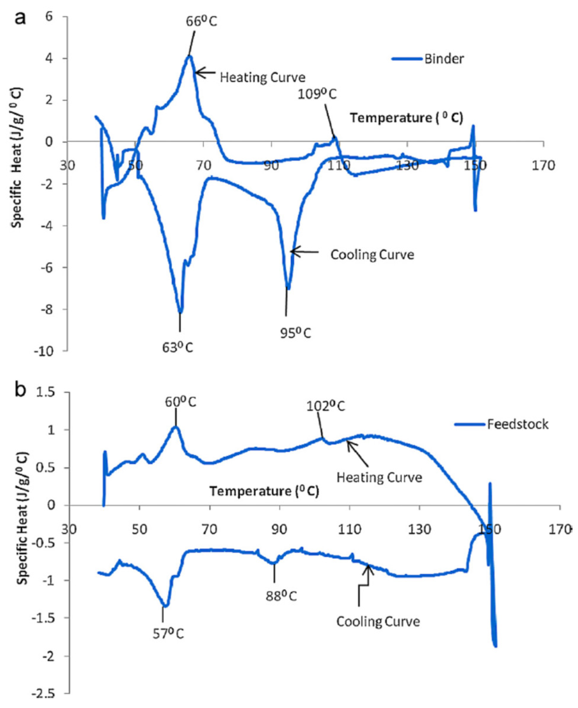 Figure 1. Specific heat of (a) binder and (b) feedstock during heating and cooling cycles derived from DSC results. Reprinted from [19] with permission from Elsevier.
Cicala and coworkers prepared and studied (via comparison with commercial-grade materials for FDM) blends of polyetherimide (PEI) and polycarbonate (PC) or polyethylene terephthalate glycol (PETG). TGA, DSC, and DMA were employed to evaluate the thermomechanical behavior of the prepared blends [20][21]. By means of DMA analysis, these authors observed a different behavior for the blends modified with PC and PETG, with a noticeable reduction in the glass transition temperature (Tg) for the PEI/PETG blends, which they observed to increase with the amount of PETG in the blend (Figure 2).
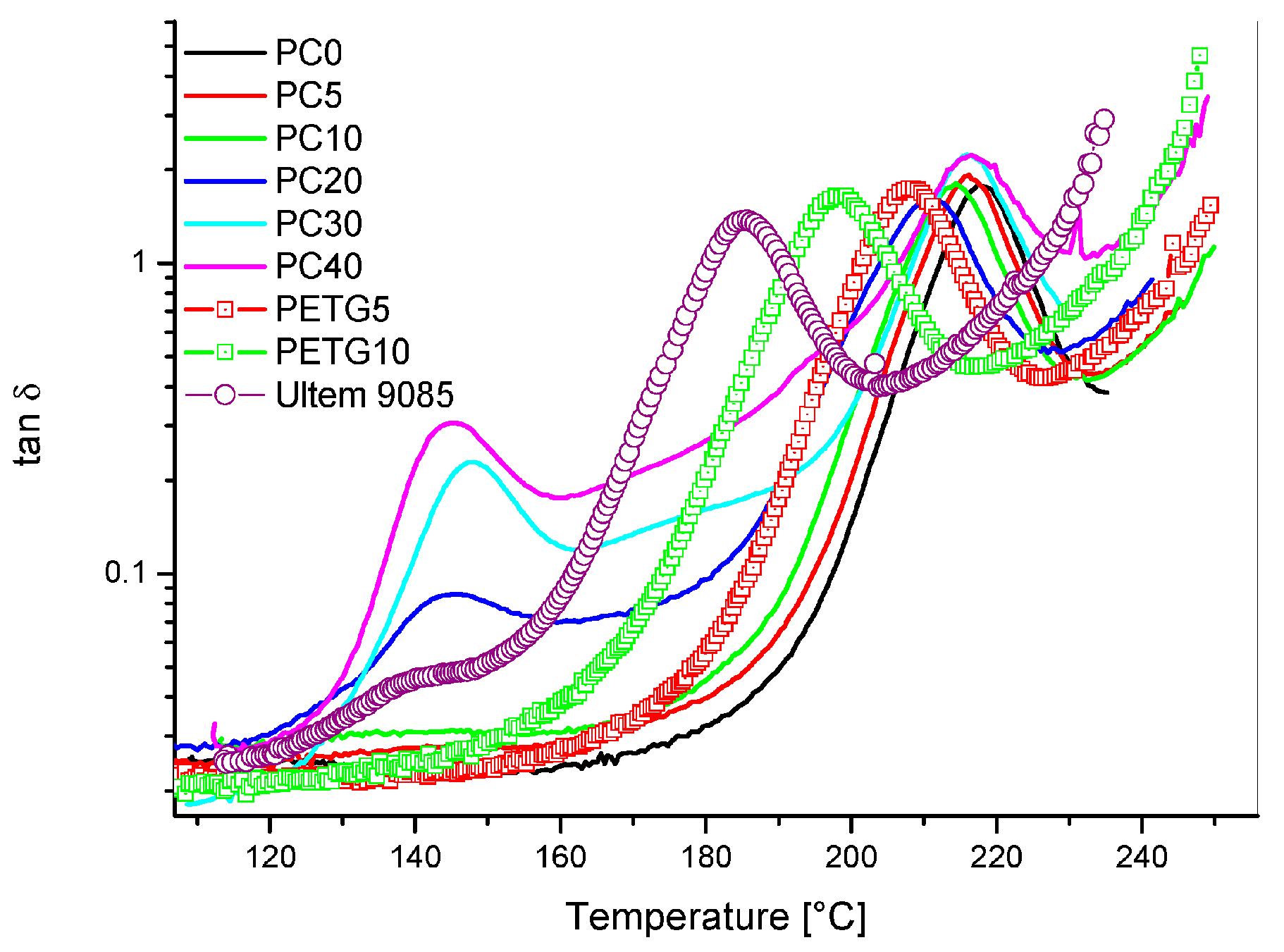 Figure 2. Tan δ versus temperature for PEI/PC and PEI/PETG blends compared to Ultem 9085: effect of PC and PETG content. Reprinted from [20] with permission from MDPI.
For the PEI/PC blend, they observed a lower reduction in Tg in comparison with a commercial formulation, as well as two single DMA peaks at a certain percentage of PC. They attributed this result to the formation of biphasic morphologies (also supported by scanning electron microscopy), which was evident upon increasing the PC amount in the blend. It is worth noting that they did not observe phase separation when the PC content was below 5 wt.% [20]. TGA was useful for their hypothesis, since it revealed two steps of degradation, thus confirming the presence of phase separation for the PEI/PC blend (Figure 3).
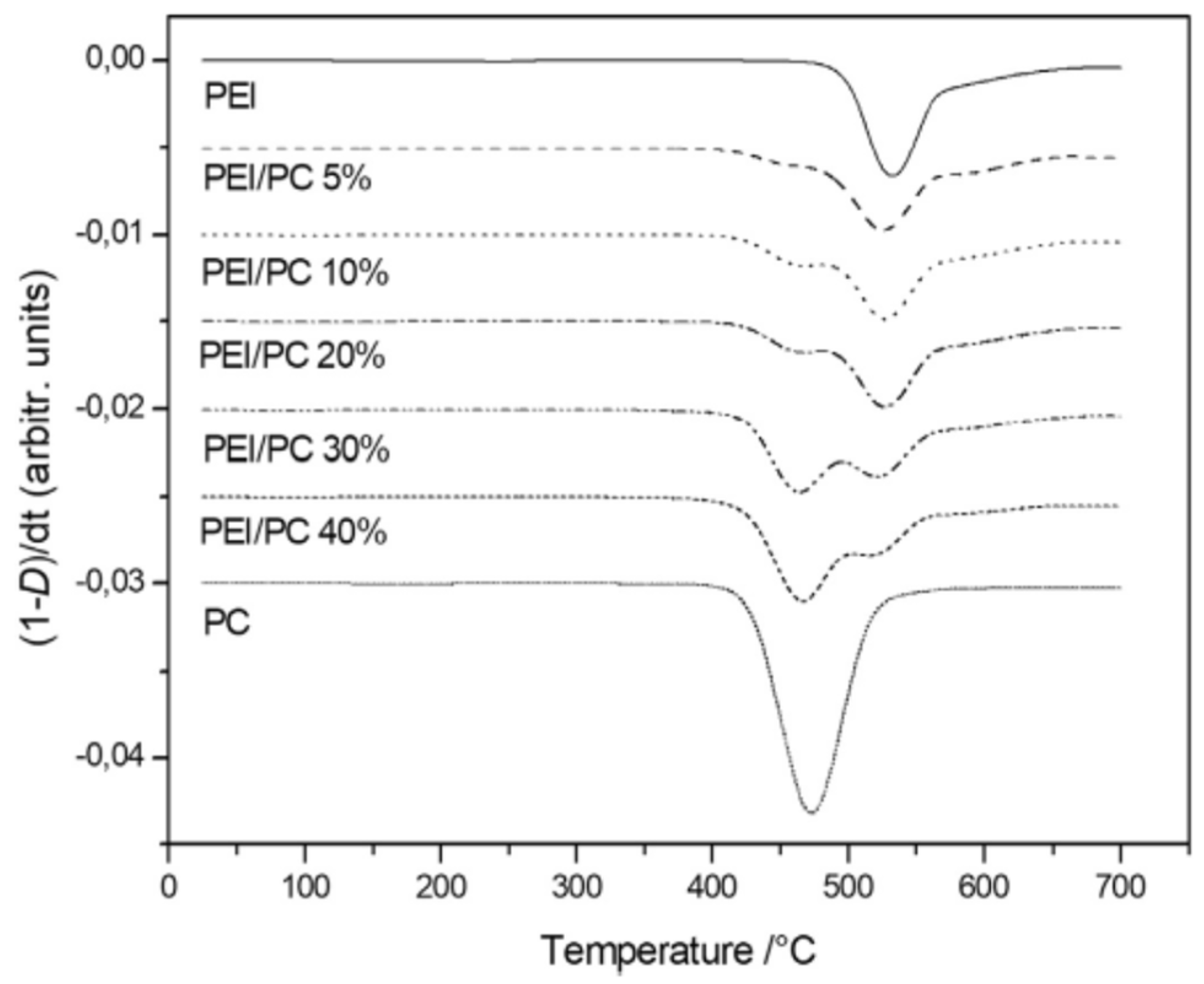 Figure 3. DTG curves in static air atmosphere for PEI, PC, and the various blends. Reprinted from [21] with permission from Elsevier.
The TGA results obtained by these authors demonstrated that PC affects the thermal behavior of the blend, with an increase in its content lowering the resistance to thermal degradation [21]. Further confirmation was obtained from DSC measurements (Figure 4), which showed two Tg peaks (one, lower, for PC-rich phases and the other, higher, for PEI-rich phases).
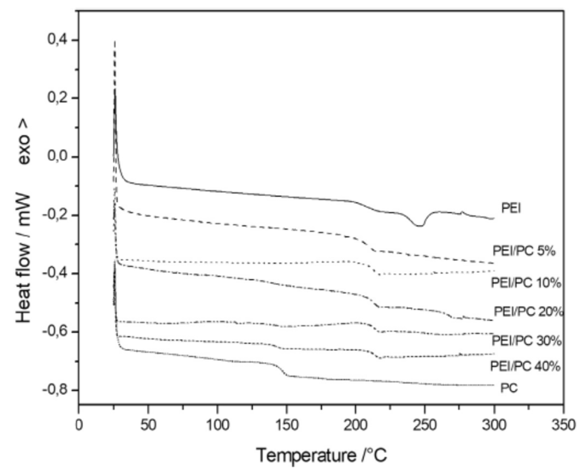 Figure 4. DSC curves for PEI, PC, and the various blends. Reprinted from [21] with permission from Elsevier.
However, Cicala and colleagues observed that the absence of the first glass transition phenomenon with low PC content and the simultaneous increase/decrease in the two Tg values, as a function of the PC content, with respect to those of pristine polymers, could result in partial miscibility regions [21]. The same research group continued studying the correlation among the thermomechanical properties and the printing quality, by characterizing different polylactide (PLA) commercial-grade filaments for FDM, via simultaneous TGA and differential thermal analysis (DTA) [22]. In this entry, they used TGA to unveil the PLA filament composition, to verify if and how it affects the printing quality. Thus, Cicala et al., managed to associate the marked shear thinning behavior, responsible for the best printing quality, with a formulation containing mineral fillers (i.e., talc). DTA allowed them to highlight significant differences in the calorimetric behavior of the filaments without talc, concluding that pure polymer filaments are not the best option for the FDM process. Another research group investigated PLA modification to increase its printing behavior; Przekop et al., used a limonene derivative of a spherosilicate (SS) as a functional additive, obtaining a significant improvement in the processing properties of the prepared hybrid composite [23]. DSC analysis allowed these researchers to demonstrate that SS–limonene promoted the plasticization of the PLA matrix, facilitating the printing process. Specifically, they observed that the variation in the crystallization and glass transition temperatures confirmed the presence of the plasticizing phase and contributed to increasing the freedom of the chains in the amorphous phase, thereby accelerating the initiation of crystallization.
Some of the most used polymers worldwide are difficult to 3D print, due to their crystallization rate. This is the case with the second-largest commercialized polymer, isotactic polypropylene (iPP). In order to reduce iPP warping during the extrusion, Wang et al., studied the non-isothermal crystallization kinetics (Figure 5) of a composite system obtained by adding spray-dried cellulose nanofibrils (SDCNF) and maleic anhydride polypropylene (MAPP) to iPP [24].
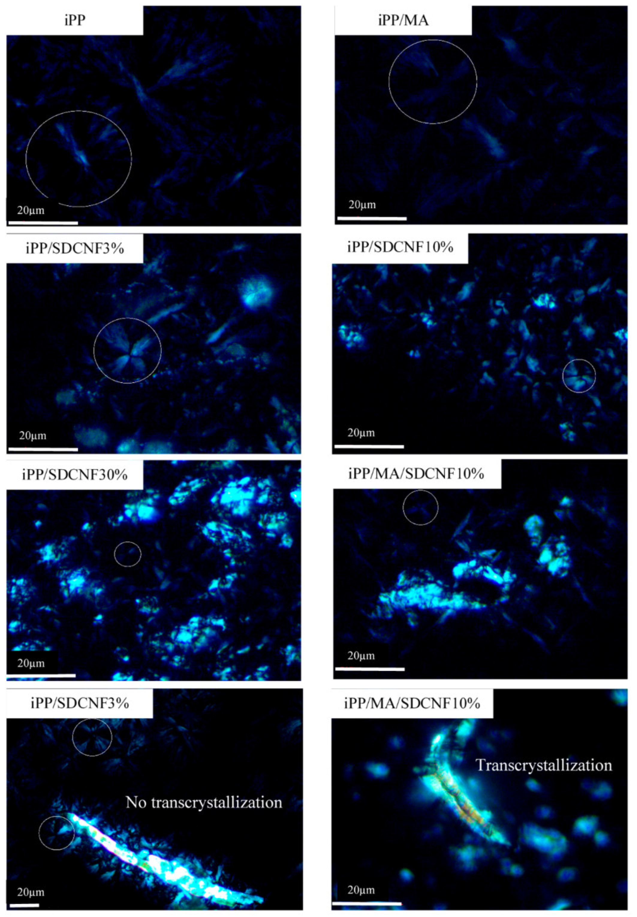 Figure 5. Polarized light micrographs of iPP and iPP/SDCNF composites. Bright and irregular-shape clumps represent SDCNF. Inside the circles are the Maltese-cross patterns of iPP spherulites. The last two graphs show the effect of maleic anhydride polypropylene (MAPP) on trans-crystallization using different scale bars. Reprinted from [24] with permission from MDPI.
They investigated, using DSC, the non-isothermal crystallization kinetics and thermal expansion of iPP. They observed that the presence of these additives in the composite restricted the crystal growth and led to a slight increase in the iPP nucleation density. This was a result of a combined action of the two additives, whereby an adequate amount of SDCNF restricted the diffusion and folding of polymer chains during crystallization, thus acting on the free volume of iPP. Furthermore, the presence of MAPP led to a reduction in the activation energy promoting the trans-crystallization. The hindering of the iPP crystal growth was confirmed by polarized light microscopy, as shown in Figure 5. In the framework of increasing the printability of acrylonitrile butadiene styrene (ABS) filaments, Khatri et al., developed a polymer–ceramic functional composite by adding barium titanate (BT) micro-powder to ABS matrix [25]. Thermogravimetric analysis was carried out to determine the ceramic content in the samples from extruded filaments and 3D prints with up to 35 vol.% BT. TG results showed a negligible thermal influence due to the polymer decomposition at high temperature during printing on the polymer–ceramic ratio throughout the process. Lamprou and coworkers proposed the substitution of the traditional poly(propylene) meshes, implanted to treat pelvic organ prolapse or stress urinary incontinence, with polyurethane (PU) ones loaded with an antibiotic manufactured by FDM to prepare safer vaginal meshes [26]. They prepared PU filaments, containing a drug used to treat urinary infections, levofloxacin, to 3D print vaginal meshes. The high-temperature regime during the 3D printing process, according to these authors, made it necessary to investigate the thermal degradation behavior of the polymer-based filaments. Furthermore, TGA was used, coupled with FT-IR, to verify the occurrence of polymer–antibiotic interactions. In particular, these authors evidenced, once again, the TA essentiality; since the drug loading was generally too low in these systems, the FT-IR spectra showed no appreciable variation with respect to PU (Figure 6), and TGA evidenced different degradation profiles. The T5% value of filaments containing levofloxacin resulted higher than of the pristine PU filaments, thus confirming the interactions of the drug with the polymer matrix.
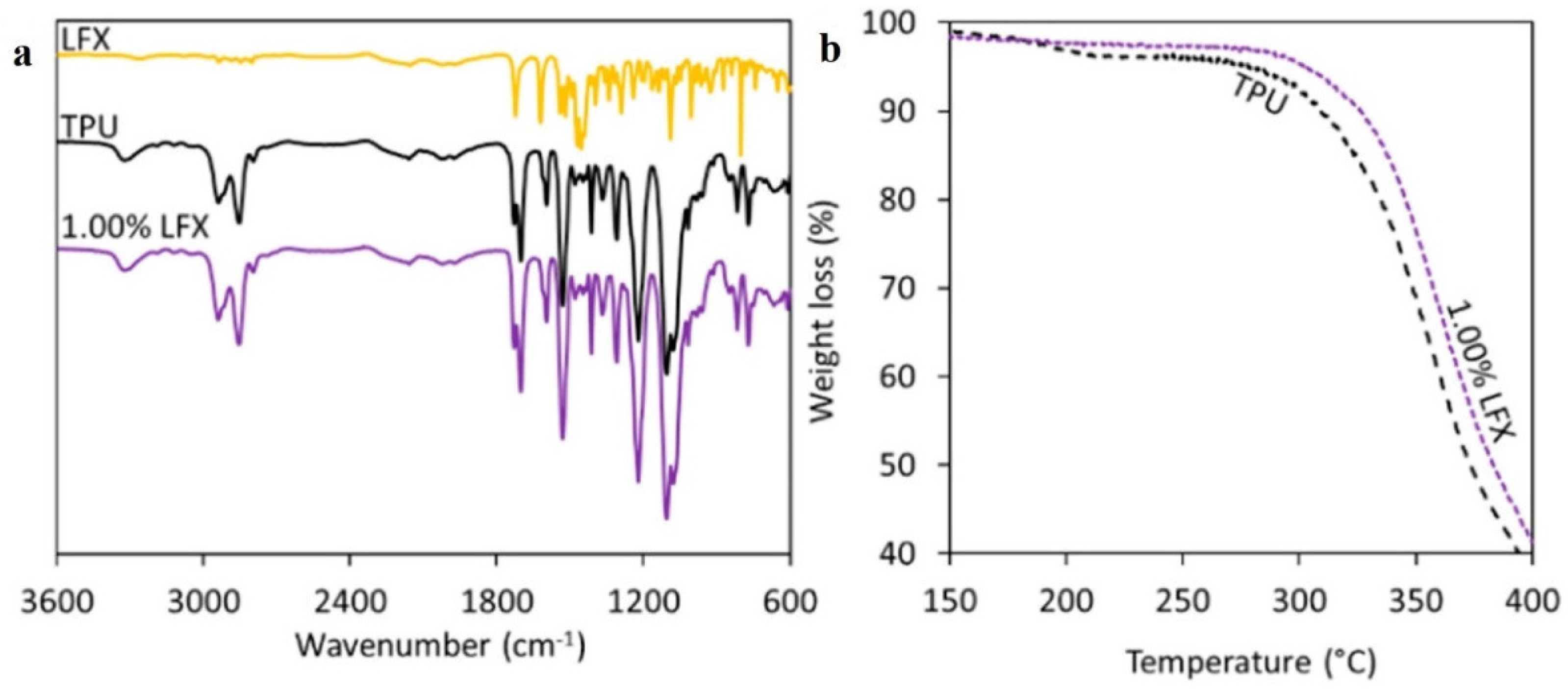 Figure 6. FTIR spectra of polyurethane (PU) and levofloxacin loaded filaments (a). TGA of PU and PU containing 1% LFX (b). Reprinted from [26] with permission from MDPI.
Similarly to plastic injection molding, replacing resin with micrometric metal powders (<20 μm) is the process of the metal injection molding (MIM) [27]. To carry out MIM, the metal is treated with various possible binders, such as thermoplastics or waxes. Considering the several factors influencing the MIM process, Mohamad Nor et al., used DSC and TGA to shed light on how the feedstock behaved along the MIM, particularly in terms of some aspects such as debinding and sintering [28]. Specifically, DSC analysis allowed them to identify the primary and secondary binder melting points, thus enabling them to map all the phenomena in the material, such as leftover of foreign particles, movements among the crystalline lattices related to the intermolecular bonds, and strengthening of the particle bonds. The same researchers used TGA to study the feedstock decomposition in terms of melting temperature, providing insight into the pyrolysis cycle design for the debinding process. As reported above, the average particle size employed in MIM is in the range from 5 to 15 μm [29], higher than the typical size of the powder used in PIM (0.3 to 0.8 μm), which is finer to prevent the plugging of nozzles. Changes in the physical and chemical properties of the powders used in PIM affect the characteristics of the obtained highly filled filaments. In their exhaustive review, Gonzalez-Gutierrez et al., attributed these changes to the different metal and ceramic sizes, as well as their morphology and chemical composition, leading to different interactions with the binder [30]. A section of this entry was devoted to the debinding, i.e., the removal process of the polymeric binder, without disrupting the shaped part printed by PIM (Figure 7).
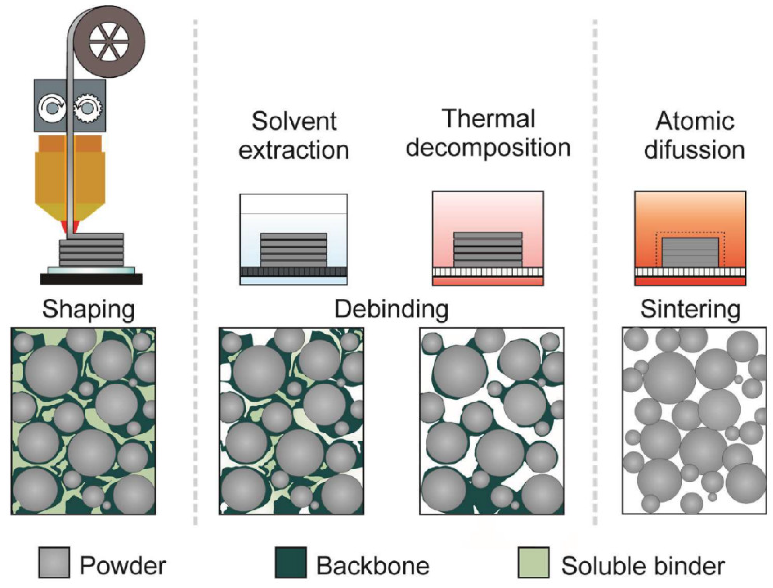 Figure 7. Schematic representation of the shaping, debinding, and sintering (SDS) process and respective morphology of the parts for the fabrication of metal, ceramic, or metal–ceramic components. Reprinted from [30] with permission from MDPI.
They highlighted the importance of this process to avoid a worse quality due to the effect of any carbon residues on the sintering. Failure to remove the binder can lead to the formation of voids and/or various different phenomena, such as surface cracking, blistering, or bloating. This critical step can be carried out, for example, using thermal methods. While reporting some examples, Gonzalez-Gutierrez and coworkers also pointed out that, commonly, the binder is removed from the printed object by heating, thus taking advantage of melting or degradation at a lower temperature, which allows detaching the printed part. Obviously, the range temperature at which the debinding is carried out depends on the designed formulation. In conclusion, the direction for AM, as indicated by these researchers, is the development of melt extrusion with new highly filled resins. The design process of these materials must take into account the polymer compatibility and the interaction with the other formulation components, and it cannot ignore the physicochemical properties of powders, stressing once again the importance of TA techniques in the characterization of materials for 3D printing.
Recently, Quarto and coworkers carried out an interesting study aimed at converting a classic FDM printer used for polymers to a printer for metal filaments. To this purpose, they changed the printer nozzle to one with a higher wear resistance [31], thus proposing a low-cost solution for producing objects with complex geometry. As reported before, the key parameter for these systems is represented by the binder. On one hand, a high amount of binder facilitates the extrusion and the adhesion of the printed part on the build plate. On the other hand, too much binder may affect the sintering phase and the shrinkage of the part [32]. Thermal treatments are necessary during the binder fraction removal and during the sintering step, providing interparticle bonding and leading to near-full densification, through a thermal cycle performed below the melting temperature [29]. They calculated the dimensions and the volume of the samples before and after the thermal treatments, recording a critical effect along the Z-axis in terms of both shrinkage value and scatter, because of the debinding and sintering. Contrariwise, they observed no changes in shrinkage along the X- and Y-axes after the thermal treatment. The attributed this behavior to the layer thickness and to the interaction between the temperature and the infill type, thus revealing the importance of optimal parameter combination in obtaining a shrinkage equal to 20%.
References
- Huang, S.H.; Liu, P.; Mokasdar, A.; Hou, L. Additive manufacturing and its societal impact: A literature review. Int. J. Adv. Manuf. Technol. 2013, 67, 1191–1203.
- Blanco, I. The Use of Composite Materials in 3D Printing. J. Compos. Sci. 2020, 4, 42.
- Hull, C.W. Apparatus for Production of Three-Dimensional Objects by Stereolithography. U.S. Patent 4575330A, 11 March 1986.
- ISO ASTM52900-15. Standard Terminology for Additive Manufacturing—General Principles—Terminology; ASTM International: West Conshohocken, PA, USA, 2015.
- Crump, S.S. Rapid prototyping using FDM. Mod. Cast. 1992, 82, 36.
- Kohár, R.; Stopka, M.; Weis, P.; Spisak, P.; Šteininger, J. Modular 3D printer concept. In Current Methods of Construction Design: Proceedings of the ICMD 2018; Medvecký, Š., Hrček, S., Kohár, R., Brumerčík, F., Konstantová, V., Eds.; Springer: Berlin, Germany, 2020; p. 484. ISBN 978-3-030-33146-7.
- Feygin, M. Apparatus and Method for Forming an Integral Object from Laminations. U.S. Patent 5354414A, 4 April 1991.
- Deckard, C. Method and apparatus for producing parts by selective sintering. U.S. Patent 4,863,538, 5 September 1989.
- Jones, R.; Haufe, P.; Sells, E.; Iravani, P.; Olliver, V.; Palmer, C.; Bowyer, A. Reprap—The replicating rapid prototyper. Robotica 2011, 29, 177–191.
- Zong, G.; Wu, Y.; Tran, N.; Lee, I.; Bourell, D.L.; Beaman, J.; Marcus, H.L. Direct selective laser sintering of high temperature materials. In Proceedings of the 3rd Solid Freeform Fabrication Symposium, Austin, TX, USA, 3–5 August 1992; pp. 72–85.
- Provaggi, E.; Kalaskar, D.M. 3D printing families: Laser, powder, nozzle based techniques. In 3D Printing in Medicine; Kalaskar, E., Ed.; Woodhead Publishing: Sawston, UK, 2017; p. 24. ISBN 978-0-08-100717-4.
- Xu, M.; David, J.M.; Kim, S.H. The Fourth Industrial Revolution: Opportunities and Challenges. Int. J. Financ. Res. 2018, 9, 90–95.
- Kudelski, R.; Cieslik, J.; Kulpa, M.; Dudek, P.; Zagorski, K.; Rumin, R. Comparison of cost, material and time usage in FDM and SLS 3D printing methods. In Proceedings of the 2017 XIII International Conference on Perspective Technologies and Methods in MEMS Design (MEMSTECH), Lviv, Ukraine, 20–23 April 2017; pp. 12–14.
- D’Aveni, R.A. 3-D printing will change the world. Harv. Bus. Rev. 2013, 91, 34–35.
- Muthu, S.S.; Savalani, M.M. Handbook of Sustainability in Additive Manufacturing; Springer: Singapore, 2016.
- Menczel, J.D.; Prime, R.B. Thermal Analysis of Polymers. Fundamentals and Applications; John Wiley & Sons, Inc.: Hoboken, NJ, USA, 2009.
- Mohamed, O.A.; Masood, S.H.; Bhowmik, J.L. Optimization of fused deposition modeling process parameters: A review of current research and future prospects. Adv. Manuf. 2015, 3, 42–53.
- Carneiro, O.S.; Silva, A.F.; Gomes, R. Fused deposition modeling with polypropylene. Mat. Des. 2015, 83, 768–776.
- Samanta, S.K.; Chattopadhyay, H.; Godkhindi, M.M. Thermo-physical characterization of binder and feedstock for single and multiphase flow of PIM 316L feedstock. J. Mater. Process. Technol. 2011, 211, 2114–2122.
- Cicala, G.; Ognibene, G.; Portuesi, S.; Blanco, I.; Rapisarda, M.; Pergolizzi, E.; Recca, G. Comparison of Ultem 9085 Used in Fused Deposition Modelling (FDM) with Polytherimide Blends. Materials 2018, 11, 285.
- Blanco, I.; Cicala, G.; Ognibene, G.; Rapisarda, M.; Recca, A. Thermal properties of polyetherimide/polycarbonate blends for advanced applications. Polym. Degrad. Stabil. 2018, 154, 234–238.
- Cicala, G.; Giordano, D.; Tosto, C.; Filippone, G.; Recca, A.; Blanco, I. Polylactide (PLA) Filaments a Biobased Solution for Additive Manufacturing: Correlating Rheology and Thermomechanical Properties with Printing Quality. Materials 2018, 11, 1191.
- Brząkalski, D.; Sztorch, B.; Frydrych, M.; Pakuła, D.; Dydek, K.; Kozera, R.; Boczkowska, A.; Marciniec, B.; Przekop, R.E. Limonene Derivative of Spherosilicate as a Polylactide Modifier for Applications in 3D Printing Technology. Molecules 2020, 25, 5882.
- Wang, L.; Gramlich, W.M.; Gardner, D.J.; Han, Y.; Tajvidi, M. Spray-Dried Cellulose Nanofibril-Reinforced Polypropylene Composites for Extrusion-Based Additive Manufacturing: Nonisothermal Crystallization Kinetics and Thermal Expansion. J. Compos. Sci. 2018, 2, 7.
- Khatri, B.; Lappe, K.; Habedank, M.; Mueller, T.; Megnin, C.; Hanemann, T. Fused Deposition Modeling of ABS-Barium Titanate Composites: A Simple Route towards Tailored Dielectric Devices. Polymers 2018, 10, 666.
- Domínguez-Robles, J.; Mancinelli, C.; Mancuso, E.; García-Romero, I.; Gilmore, B.F.; Casettari, L.; Larrañeta, E.; Lamprou, D.A. 3D Printing of Drug-Loaded Thermoplastic Polyurethane Meshes: A Potential Material for Soft Tissue Reinforcement in Vaginal Surgery. Pharmaceutics 2020, 12, 63.
- Froes, F.H. Getting better: Big boost for titanium MIM prospects. Met. Powder Rep. 2006, 61, 20–23.
- Mohamad Nor, N.H.; Ismail, M.H.; Abu Kasim, N.A.; Muhamad, N.; Taib, M.A. Characterization and rheological studies on ready-made feedstock of stainless steel 316L in metal injection molding (MIM) process. In Applied Mechanics and Materials; Trans Tech Publications Ltd.: Bäch, Switzerland, 2013; Volume 465–466, pp. 709–714.
- Gonzalez-Gutierrez, J.; Stringari, G.; Emri, I. Powder injection molding of metal and ceramic parts. In Some Critical Issues for Injection Molding; Wang, J., Ed.; IntechOpen: Rijeka, Croatia, 2012; pp. 65–86.
- Gonzalez-Gutierrez, J.; Cano, S.; Schuschnigg, S.; Kukla, C.; Sapkota, J.; Holzer, C. Additive Manufacturing of Metallic and Ceramic Components by the Material Extrusion of Highly-Filled Polymers: A Review and Future Perspectives. Materials 2018, 11, 840.
- Quarto, M.; Carminati, M.; D’Urso, G. Density and shrinkage evaluation of AISI 316L parts printed via FDM process. Mat. Manuf. Processes 2021, 36, 1535–1543.
- Annoni, M.; Giberti, H.; Strano, M. Feasibility Study of an Extrusion-based Direct Metal Additive Manufacturing Technique. Procedia Manuf. 2016, 5, 916.
More
Information
Subjects:
Engineering, Manufacturing; Chemistry, Physical
Contributor
MDPI registered users' name will be linked to their SciProfiles pages. To register with us, please refer to https://encyclopedia.pub/register
:
View Times:
1.8K
Revisions:
2 times
(View History)
Update Date:
29 Mar 2022
Table of Contents


Notice
You are not a member of the advisory board for this topic. If you want to update advisory board member profile, please contact office@encyclopedia.pub.
OK
Confirm
Only members of the Encyclopedia advisory board for this topic are allowed to note entries. Would you like to become an advisory board member of the Encyclopedia?
Yes
No
${ textCharacter }/${ maxCharacter }
Submit
Cancel
Back
Comments
${ item }
|
${ item.createdUser.fullName }
${ item.createdAt }
${ item.vote }
${ item.reply }
Delete
${ reply.createdUser.fullName }
${ reply.createdAt }
${ reply.vote }
Delete
There is no reply to this comment~
${ item.replyTextCharacter }/${ item.replyMaxCharacter }
Submit
Cancel
More
No more~
There is no comment~
${ textCharacter }/${ maxCharacter }
Submit
Cancel
${ selectedItem.replyTextCharacter }/${ selectedItem.replyMaxCharacter }
Submit
Cancel
Confirm
Are you sure to Delete?
Yes
No