Your browser does not fully support modern features. Please upgrade for a smoother experience.
Submitted Successfully!
 +1 credit
Thank you for your contribution! You can also upload a video entry or images related to this topic.
For video creation, please contact our Academic Video Service.
| Version | Summary | Created by | Modification | Content Size | Created at | Operation |
|---|---|---|---|---|---|---|
| 1 | Marcus Evandro Teixeira Souza Junior | + 4209 word(s) | 4209 | 2022-03-21 02:58:09 | | | |
| 2 | Peter Tang | Meta information modification | 4209 | 2022-03-22 04:06:05 | | |
Video Upload Options
We provide professional Academic Video Service to translate complex research into visually appealing presentations. Would you like to try it?
Cite
If you have any further questions, please contact Encyclopedia Editorial Office.
Souza Junior, M. Power Electronics for Distributed Generation. Encyclopedia. Available online: https://encyclopedia.pub/entry/20828 (accessed on 18 July 2026).
Souza Junior M. Power Electronics for Distributed Generation. Encyclopedia. Available at: https://encyclopedia.pub/entry/20828. Accessed July 18, 2026.
Souza Junior, Marcus. "Power Electronics for Distributed Generation" Encyclopedia, https://encyclopedia.pub/entry/20828 (accessed July 18, 2026).
Souza Junior, M. (2022, March 22). Power Electronics for Distributed Generation. In Encyclopedia. https://encyclopedia.pub/entry/20828
Souza Junior, Marcus. "Power Electronics for Distributed Generation." Encyclopedia. Web. 22 March, 2022.
Copy Citation
Power electronics is formed by technologies that, through advanced controls of semiconductor devices, efficiently convert electrical energy for appropriate use in many areas. Distributed generation (DG), mainly renewable energy, is a group of power sources that can be installed in distinct points of the power system or be isolated, such as: wind power, photovoltaic systems, fuel cells, small hydro, and microturbines. Power converters are a crucial technology for the integration of DG into the modern sustainable power system, including microgrids and smart grids structures. They allow correct adaptation, but also enable DG units to fully realize their potential benefits in their wide variety of configurations.
distributed generation (DG)
microgrids
power electronics
renewable energies
smart grids
static converters
1. Introduction
Power electronics, the field where semiconductor equipment is studied and developed for the efficient conversion of electrical energy, through advanced control methods, has been playing an increasingly important role in the world. Their devices find applications in the most varied areas of technology, involving electricity. Industrial, mobility and energy sectors raise their productivities and improve the quality of their services when making use of them [1].
At the same time, distributed generation (DG), mainly in the form of renewable energies, has aroused great interest in recent years, due to its admirable potential benefits, such as reduction in the emission of greenhouse gases and pollution in general, improvements in reliability and in power quality, private production of electricity, employment generation, among others [2][3]. Its adoption, and that of its related technologies of microgrids and smart grids, seems the right way to achieve the Sustainable Development Goal (SDG) 7 of the United Nations’ 2030 Agenda, for ensuring “access to affordable, reliable, sustainable and modern energy for all” [4]. It is not by chance that DG has expanded and penetrated all the points of the power system. Indeed, the total installed capacity in the whole world of the most acclaimed sources of DG, solar photovoltaic and wind power, grows exponentially, with the former rising from about 72 GW to 710 GW, and the second from approximately 220 GW to 732 GW, between 2011 and 2020 [5].
2. Power Electronics and Distributed Generation
Here, DG is defined as any electric power production technology that can be easily installed in a great variety of geographic and physical locations, regardless of where it is connected (transmission, distribution or consumption side) and of its size, being spread throughout the entire power system or isolated. It, therefore, encompasses wind power, photovoltaic systems, fuel cells, small hydro, cogeneration, biomass energy, small thermal generators and other sources [2].
These technologies, however, have the most distinct electric outputs, while the power system requires current, voltage and frequency standardized parameters. To solve this problem in such a way that none of these devices are disturbed or damaged, there must be means to connect the two. The equipment that accomplishes this task is called “interface”. According to some authors [6][7], and with the IEEE 1547 standard [8], the interfaces can be divided into three basic categories: synchronous machines (SM), induction machines (IM) and power electronics converters. The former two are part of systems that must convert mechanical power to electric power. The output can be, or not, appropriated for the power system. The converters, in turn, are imperative for some sources and can improve the performances of other ones, even if they are already composed of SM or IM. Figure 1 illustrates the connection of DG with the power system through power electronics.
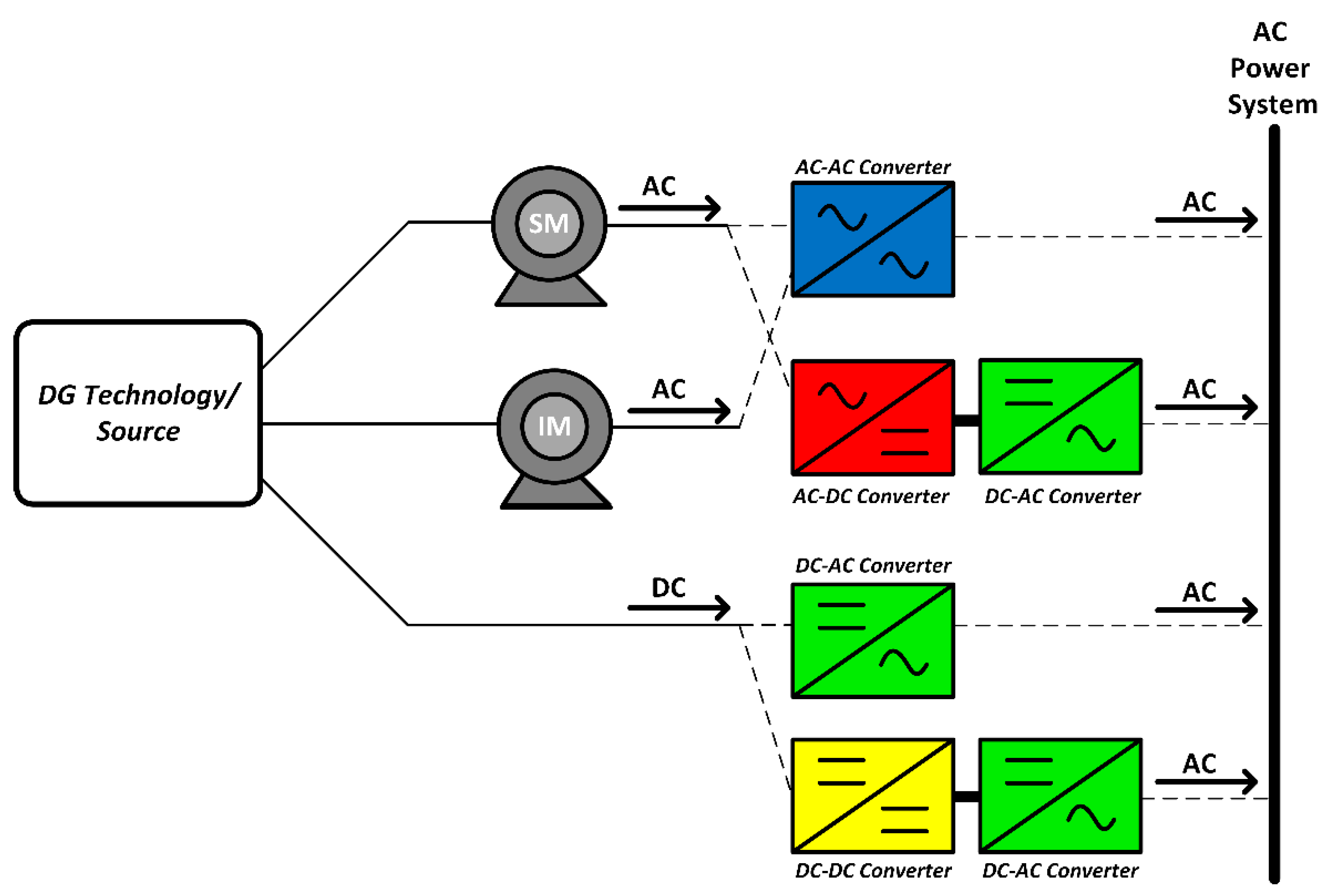
Figure 1. Main DG interface configurations with power converters. Alternating current (AC) and direct current (DC).
The result of using static converters is that all of the power system’s requirements are attended with high efficiency, but not only that. Other positive characteristics from these DG devices can be provided, such as the provision of ancillary services, active grid management, maximum power extraction, harmonics control, reactive support and voltage regulation [9]. In the next sections, particular DG cases, with the use of power electronics as interface, are explored.
3. Power Electronics and Wind Power
Wind power is the technology that transforms the energy from the wind into electricity. This conversion is realized by wind turbines, with the horizontal axis with three blade types being the most used [10]. One of its classifications makes clear the strong bond with power electronics, since the division is given by the degree of dependence with it. Namely, wind turbines can be independent, partially dependent or totally dependent on power electronics converters as interface [11]. Each one of them will be exposed, but it is interesting to notice, beforehand, that even the operation of the independent ones can be enriched with the use of converters. Other classification is based on the speed; if it is or is not variable [12][13]. Relating these two classifications, it can be verified that the independent one does not have variable speed, while the others have.
Wind turbines independent of power electronics (Figure 2a) are coupled directly with the grid, by induction generators with a squirrel-cage rotor. With torque variations, its speed changes minimally (1−2%), which leads to it being considered fixed. Besides that, by the type of the generator used, the turbine requires reactive power absorption. This compensation can be done by the grid or, more usually, locally, by switched capacitor banks (5 to 25 steps) [11]. The biggest advantage of power electronics for this category is in the initial connection of the turbine to the power system. When this occurs, there is a transient with high inrush currents. These currents can have their values substantially reduced with the use of a thyristor converter, the soft starter. After this transient regime, a bypass switch connects the wind turbine directly to the grid [14]. Advantages of the independent turbines that can be considered are the simple construction, the low cost and the absence of complex converters. The disadvantages are the constant speed, the mechanical reinforcements necessary to avoid wear [13] and the possibility of flicker appearance, if the grid is weak, as a consequence of the wind fluctuations [12].
The second classification of turbines, partially dependent, can be partitioned as follows: rotor resistance and doubly fed induction generator (DFIG). Both of them are more complex and expensive solutions. In contrast with the independent ones, however, these have variable speed. In the first one (Figure 2b), this variation is partial, and it differs a little in its structure from those of non-variable speed. The only two modifications are that the rotor is a wounded one and one external variable resistance, controlled by a power electronics converter, is connected to it. This allows for changes in the machine slip, and consequently, although small, in its speed and its output power.
For the DFIG (Figure 2c), the rotor is still the wounded one. However, it is connected, via slip rings, to the power system by a back-to-back converter (AC-DC with a DC-AC) that controls its frequency and, therefore, its speed. The stator is directly coupled to the grid. The first advantage is that, with a small converter (30% of the nominal power of the turbine), a broad variation of speed can be achieved (typically 30% higher or lower than the synchronous speed). The second advantage is the control of the active and reactive powers. In the case of the latter, the compensation is made internally, dispensing the use of capacitor banks. This configuration also makes a smooth connection with the grid, without external means [14]. With these advantages, the wind turbine can participate in ancillary services, besides contributing with improvements in power quality. One last interesting advantage is the reduced noise, due to the low speed with calm winds. On the other hand, one disadvantage is the presence of harmonics of high frequency, which forces the installation of filters in wind parks [13].
The third and last category, the totally dependent wind turbines (Figure 2d), has its electric machines fully connected to the power system with power electronics as the interface (back-to-back). There are various benefits. Beyond the complete speed variation, there is the intern reactive compensation, the smooth connection to the grid [12] and the fast and complete control of active and reactive powers [13]. In contrast, the converter adds losses, complexity and sensibility to the system. The electric machine in this category can be the induction generator of the squirrel-cage rotor type, the conventional synchronous generator (with few poles), the multiple-pole synchronous generator and the permanent magnet (PM) synchronous generator. These last two have the great advantage of eliminating the use of the gearbox. The removal of this item, also present in the other two categories of wind turbines, provides the system with lower maintenance, losses and costs and greater reliability [15]. When synchronous generators, with the exception of the PM, are adopted, the field excitation can be done with the addition of a small rectifier, whose input is the power system itself.
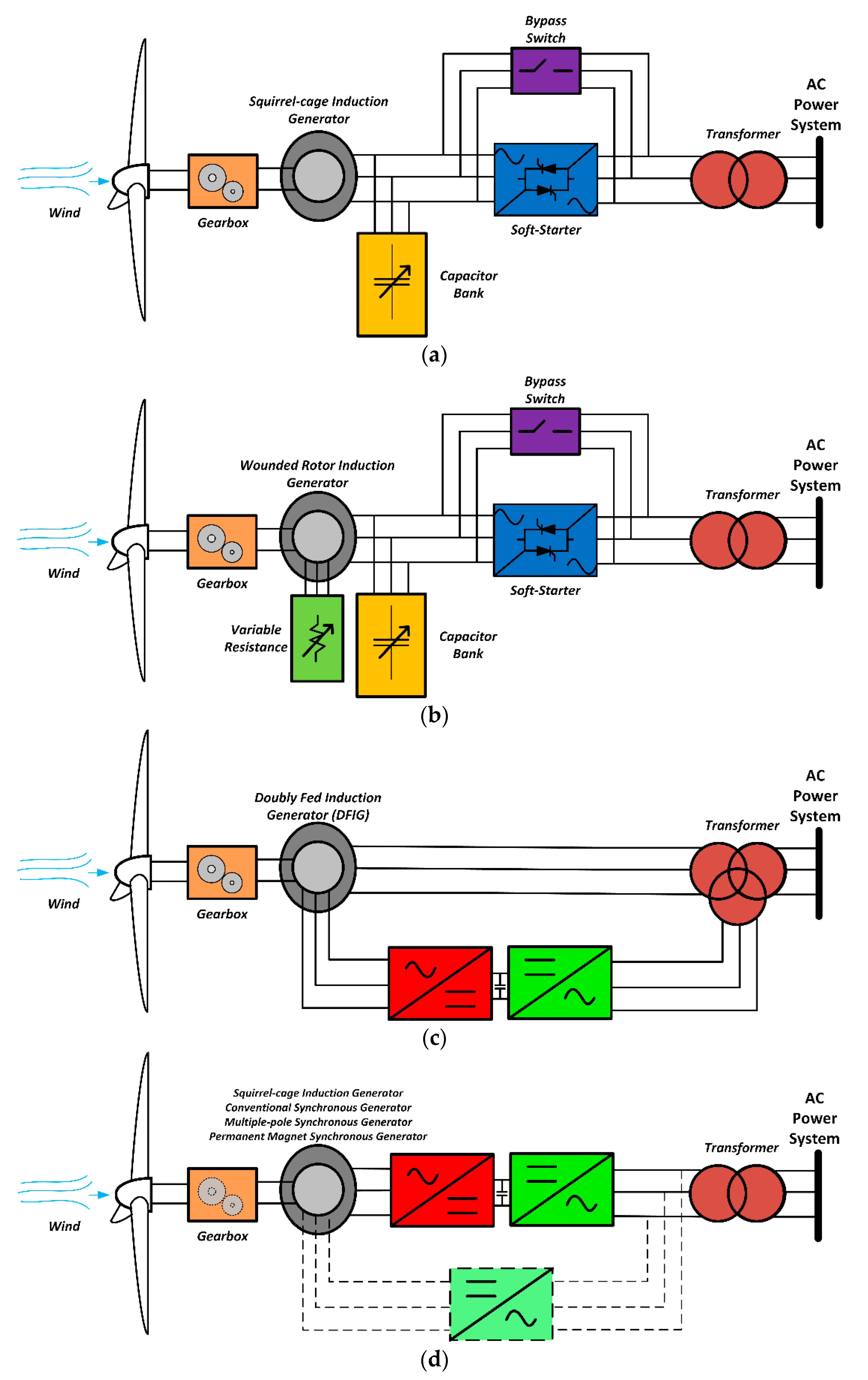
Figure 2. Wind turbine configurations: (a) independent, (b) partially dependent with rotor resistance, (c) partially dependent DFIG and (d) totally dependent of power electronics.
A 2016 report [16] showed that power electronics, independent and partially dependent with rotor resistance wind turbines, have an almost insignificant relative participation in global market share since 2013. In 2015, for onshore wind parks, the DFIG category was still the favorite one, with an installed capacity of approximately 50% in Europe and around 75% in Asia, North America and the rest of the World. In Europe, however, totally dependent wind turbines also have a nearly 50% market share. In offshore wind parks, this last class is dominant. The different configurations follow a proportional relationship with the wind turbine nominal power. The DFIG concept is the most used for those turbines below 2 MW, while the totally dependent is the preferred solution for capacities higher than that [16]. As there is a strong trend in growing power rating for wind turbines with an average size of 2.6 MW onshore and 5.7 MW offshore machines delivered in 2019, and configurations as large as 12 MW [17], and because of its advantages, such as full power controllability, the totally dependent category will soon be completely predominant in the wind power industry.
4. Power Electronics and Photovoltaic Systems
Photovoltaic systems are formed by photovoltaic cells that transform the sunlight directly into electricity. One group of connected cells is called a photovoltaic module or panel, while a photovoltaic array can be considered either a synonym of the latter, or a larger system, formed by several of them connected in series or parallel [18]. The union of panels, in series, also receives a special name: photovoltaic strings. Each one of these schemes provides different voltages, currents and powers. However, for all of them, the output is DC, which makes power electronics mandatory for most parts of the applications.
The apparatuses, which make possible the corresponding electrical link between the photovoltaic arrays and the AC systems, are called indistinctly solar inverters, and may be composed of a single AC-DC stage or by two stages, having one or more DC-DC converters at the front of an inverter itself. Depending on the arrangement between the arrays and the converters and their number, the solar inverters can be classified in five categories, as shown in Figure 3, Figure 4 and Figure 5.
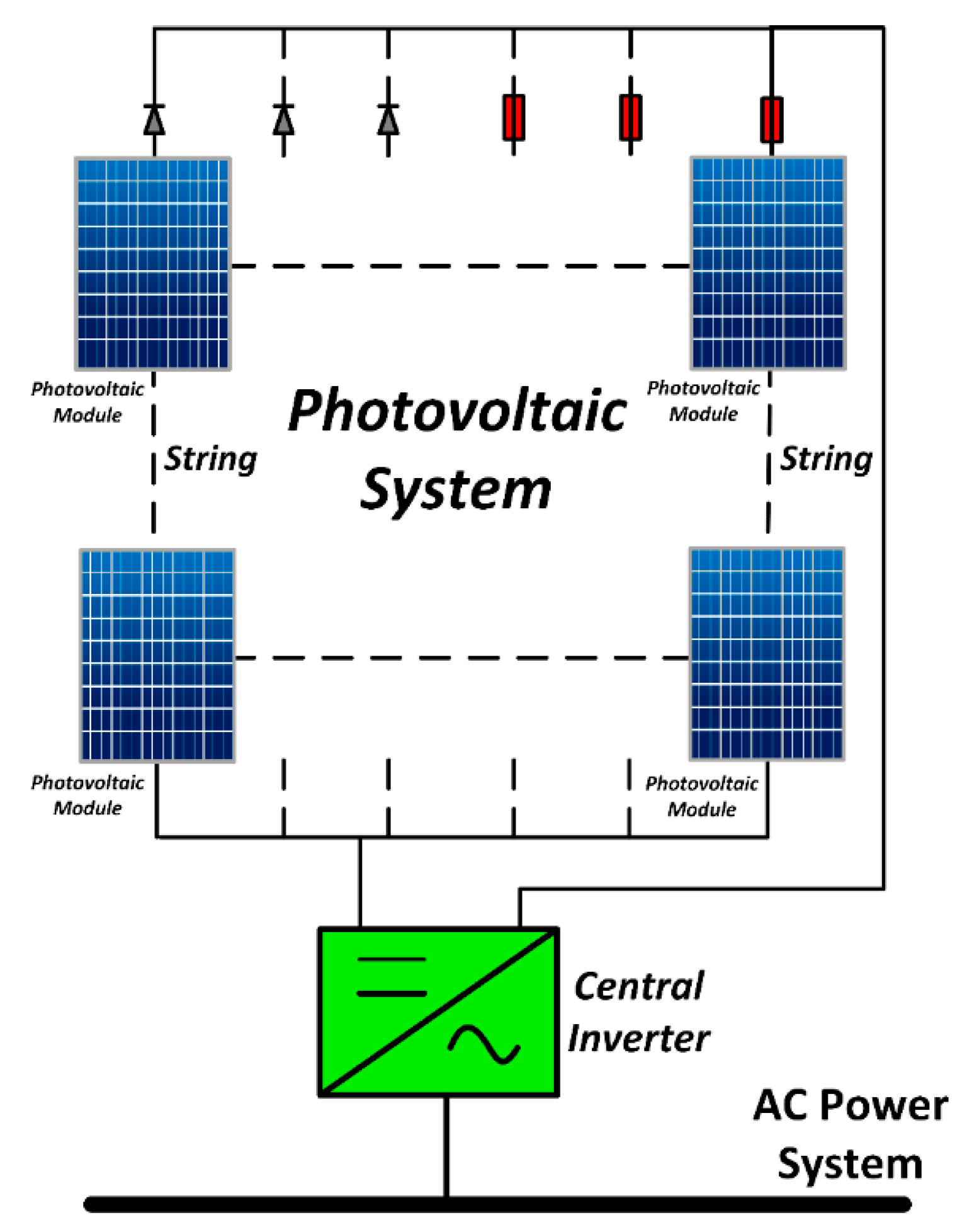
Figure 3. Solar central inverter configuration.
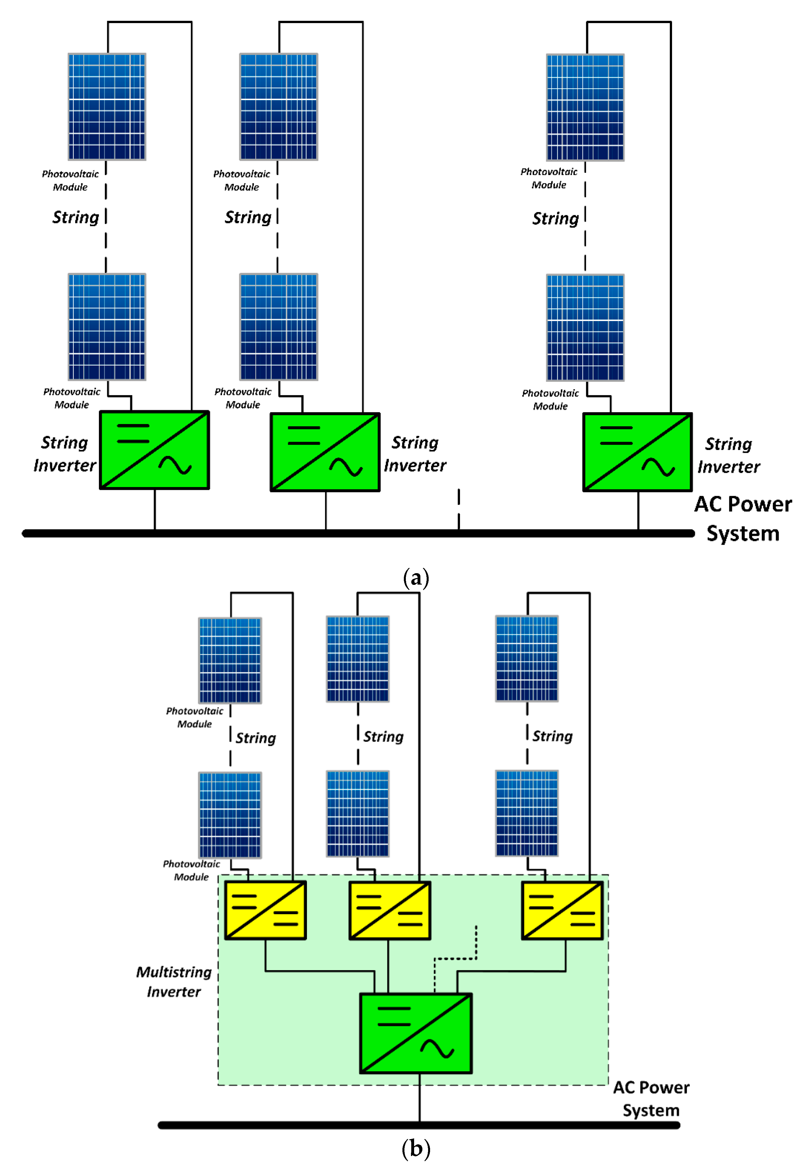
Figure 4. Solar inverter configurations: (a) string inverter and (b) multistring inverter.
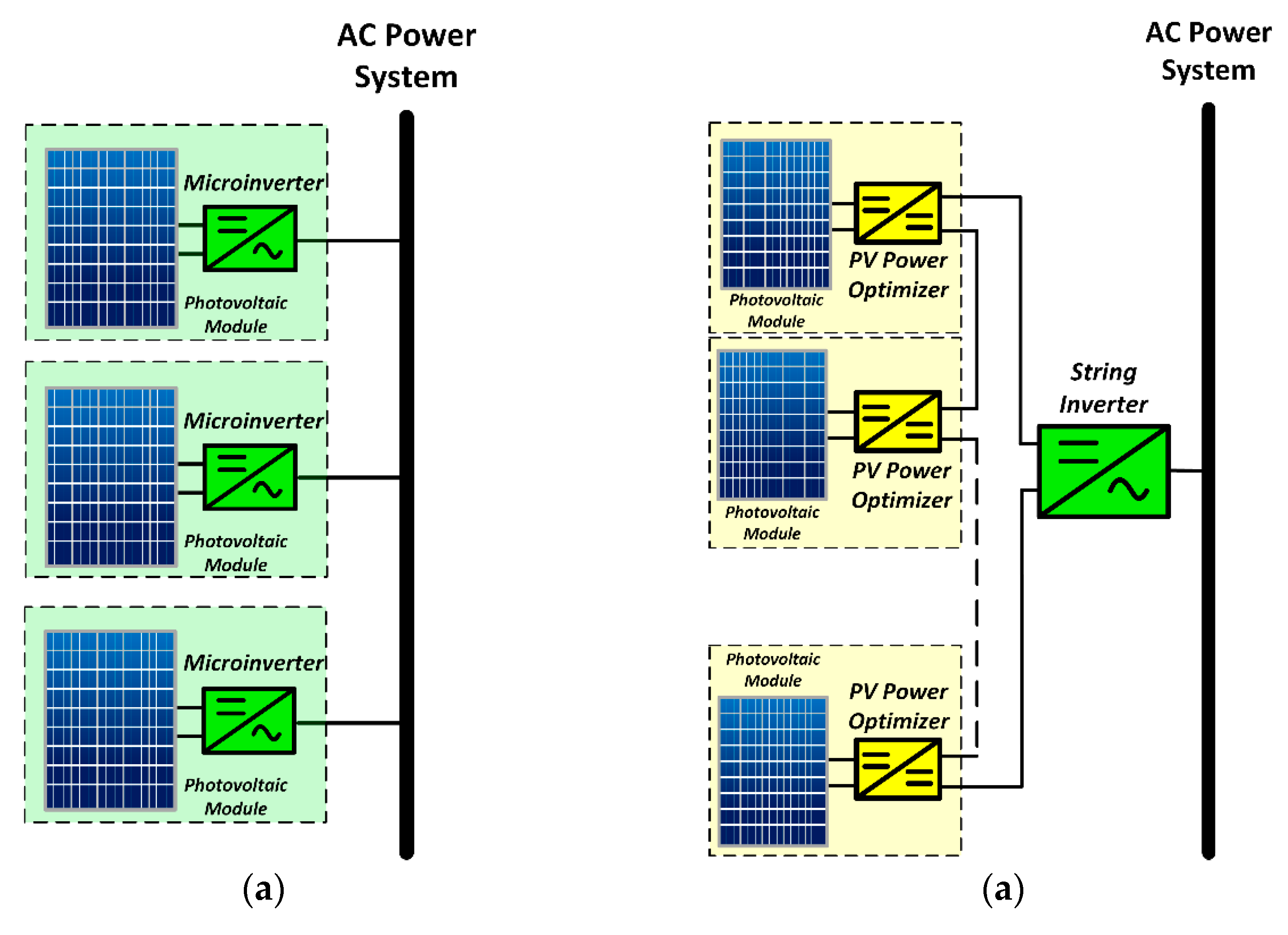
Figure 5. Solar inverter configurations: (a) microinverter and (b) photovoltaic power with power optimizer.
The central inverters (Figure 3) are commonly adopted for systems with relatively high powers and a large number of photovoltaic panels. A single unit can satisfy the entire array. Not infrequently, the strings present in these cases provide voltage high enough to dispense a DC-DC step-up stage or a transformer. On the other hand, diodes or fuses are inserted in each one of them for protection against reverse currents. Some disadvantages are the use of a single maximum power point tracking (MPPT) system, the lack of reliability because of the dependence on only one inverter unit for a big array, the incompatibility between the panels, the losses in the diodes and the use of high voltage DC cables [19].
The second configuration is the one of string inverters (Figure 4a) that are, as the name indicates, the ones that are dedicated to each one of the strings. This characteristic allows a higher yield, since the MPPT is oriented and diodes are not used. Again, if the voltage for each string is satisfactory, then there is no need for additional devices to elevate the voltage.
The third category is the one of multistring inverters (Figure 4b). This one is composed of DC-DC converters for each one of the strings and a single DC-AC converter common to all of them. The greatest advantage is the increased efficiency due to the MPPT being individual for each string and having more control. Aside from this, there is an increase in the flexibility because strings from different technologies and orientations can have a unique connection, in addition to the owner being able to later increase the number of panels of its power plant [15].
The fourth of the five configurations is that of the microinverters (Figure 5a). These are connected in one, two, three or four PV(Photovoltaic) modules, having a DC-DC converter, being two-stage or single-stage, with or without a high frequency transformer. The MPPT is panel individual, which augments, considerably, the efficiency and the compatibility. Another interesting characteristic is the fact that the use of microinverters makes the panels plug-and-play devices. In other words, even people with little knowledge of photovoltaic systems can easily install and connect this category. Another consequence is a more flexible arrangement of the panels. In its turn, the high cost of having a single inverter for only one or two panels is a disadvantage [19]. More disadvantages are the narrow MPPT voltage range and the low reliability in the long term, since the system is susceptible to more failures, due to the high temperatures it can reach (more than 60 °C in some cases).
The last configuration of solar inverters is that of the photovoltaic power optimizers (Figure 5b). They are an enhancement of the string inverter, with some benefits of the microinverters. Each one of them is a DC-DC converter that is attached directly to the photovoltaic module, which gives them individual MPPT, yielding a higher efficiency and a wide MPPT voltage range. The photovoltaic power optimizers and the photovoltaic modules are connected in series, forming a string, which, in turn, is connected to a string inverter. The entire system is, therefore, simple, has a high reliability and has fewer components. On the other hand, some of the disadvantages are the high cost, a minimal string length and an improved security system, due to the risk of arcing on the DC wires between the photovoltaic modules and the string inverter [20].
A factor that is important to highlight is the presence, or not, of transformers in the inverters’ topologies. The use of them, no matter the type, brings galvanic isolation. However, both types, the high frequency transformer of DC-DC converters and the one with low frequency, connected to the grid, diminishes the efficiency of the system. The second one also impairs the inverters by expanding the space occupied, increasing weight, elevating its costs and making the installation more difficult. Proposing to remedy these problems, the more used option has been the transformerless inverters, where the transformer is absent [21][22].
The challenges of adopting this solution begin by the complexity of the topologies. The structures are based, primarily, on the groups of the Full-bridge and Neutral Point Clamped (NPC) single-phase inverters. In the first case, the classical H-bridge, with bipolar, unipolar or hybrid modulation is a trend, as well as the others, more developed, such as the H5, the HERIC, that with DC bypass and the zero-voltage rectifier. For the second type, the classical NPC and the Conergy NPC are available. What explains the large range of strategies is the search for transformerless inverters that are more efficient, secure, smaller and less expensive [22]. Each one of them tries to get, for example, higher efficiency, with the achievement of a zero-voltage stage, avoiding reactive power exchange between the grid and the DC side capacitor, a decrease in or the elimination of the high-frequency content and the reduction in the filters’ requirement [23].
For this transformerless inverters family, great attention must be given to the parasitic capacitors and their leakage currents. The structure of the panels, formed by semiconductors, glass and aluminum, linked to the lack of galvanic isolation, brings up a capacitance and possible currents that can bring risks to people and animals. The calculated value of this capacitance is around 50 and 150 Nf/Kw and depends on various factors, including humidity, distance between the panel and the surface of installation, the material of the cells, among others [24]. The importance of this leakage current is so great that it is determinant in the choice of the transformerless topology [21][22].
One important component of the photovoltaic systems that can be addressed is the MPPT. Perturb and Observe (P&O), Hill Climbing and Incremental Conductance are the more known [25][26], and will be explained here. Nevertheless, there are several others proposed, including more complex methods that use artificial intelligence techniques, such as fuzzy logic and neural networks [27][28]. Recently, even more advanced techniques were proposed and developed, including the musical chairs algorithm (MCA) [29], optimal fuzzy control [30] and nested particle swarm optimization (PSO) [31] methods. The MPPT methods make the photovoltaic arrays work by producing the maximum power available, as changes in irradiation, temperature and in their respective loads, modify their performances. This is reflected in changes in their I-V and P-V operation characteristic curves. The relevance of power electronics is, again, justified here. It is thanks to the DC-DC converters, working with a microcontroller or a digital signal processor (DSP), that the MPPT methods are easily applied. The P&O, as well as the Hill Climbing, operate by disturbing the duty cycle of the DC-DC converter, providing variations (voltage variations for the former and power variations for the latter) that change the point of operation, where the system is working in the P-V curve until it reaches its maximum. The algorithm of the incremental conductance is based on the analysis of the incremental (I/V) and the instantaneous (ΔI/ΔV) conductances. The comparison between the two indicates, with respect to the position of the current point of operation, the position of the maximum power point. Fixed increments of voltage by the DC-DC converter make this point to be reached.
As, specifically, for DC-DC converters, their main functions for photovoltaic applications are voltage regulation and MPPT control, they can be divided in the isolated and non-isolated categories. In the first classification, the buck and boost converters, despite being the cheapest ones, are not well suited because of their weak characteristics in tracking the maximum power point (MPP). The Buck-Boost, Cúk and SEPIC converters have good performance in MPPT, with optimal outcomes. The formal is used in low-power systems, while the last two are better choices for medium-power solutions. In the case of the isolated converters, the flyback-based converters show good results, with high efficiency. In high-power systems, however, H-bridge schemes are superior, mainly in cascaded and multilevel structures. It is important to highlight that the application of any MPPT technique is independent of the topology chosen [32].
5. Power Electronics and Fuel Cells
Fuel cells convert chemical energy into electric energy without moving parts and with high efficiency. Pure hydrogen, the main fuel of these devices, does not exist in nature abundantly, but there are many renewable and sustainable sources, such as biomass and solar energy, and methods, including biological processes and plasma reformation, that can be used to produce it [33]. The residues are, generally, only water and heat, with virtually zero greenhouse gases emissions. Besides that, they have high energy density, being up to ten times that of batteries [34]. It is a promising technology with many applications [35], but it still comes at a high price. Power electronics have two roles to make them viable: allow proper operation and reduce costs.
The output of these devices is DC and, therefore, the interface is similar to the one used in photovoltaic systems, the conversion from DC to AC being mandatory for the most part of the applications. The theoretical maximum voltage that each cell produces is 1.2 V [34]. Just like the photovoltaic cells, the fuel cells can be connected together in series and in parallel, to obtain higher levels of voltage and current. With lower power ratings, an inverter stage may be sufficient. In this situation, the number of components is small, the switching losses and frequency variations are lower, and the efficiency is higher. However, since DC voltage in low-power fuel cell systems (less than 1 Kw) is low and applications require higher voltages, a high-gain DC-DC stage is a good solution. On the other hand, when the power rating is superior, this additional stage is largely employed to avoid the use of low-frequency transformers, which are expensive, bulky and heavy. A high-frequency transformer is appropriate in this case due to the lower cost [36]. In addition, the DC-DC converter is very important because it performs the DC isolation function for fuel cell systems [11] and controls the voltage profile, since the fuel cells have some restrictions, such as lower performance with more ripple current, problems with currents in reverse direction and slow response to load changes [37]. It also allows integrated power factor correction and enables proper operation as uninterruptible power supply (UPS) systems [38]. The application of a high-frequency inverter, followed by an AC-AC converter, is also an option [11]. These main structures are illustrated in Figure 6.
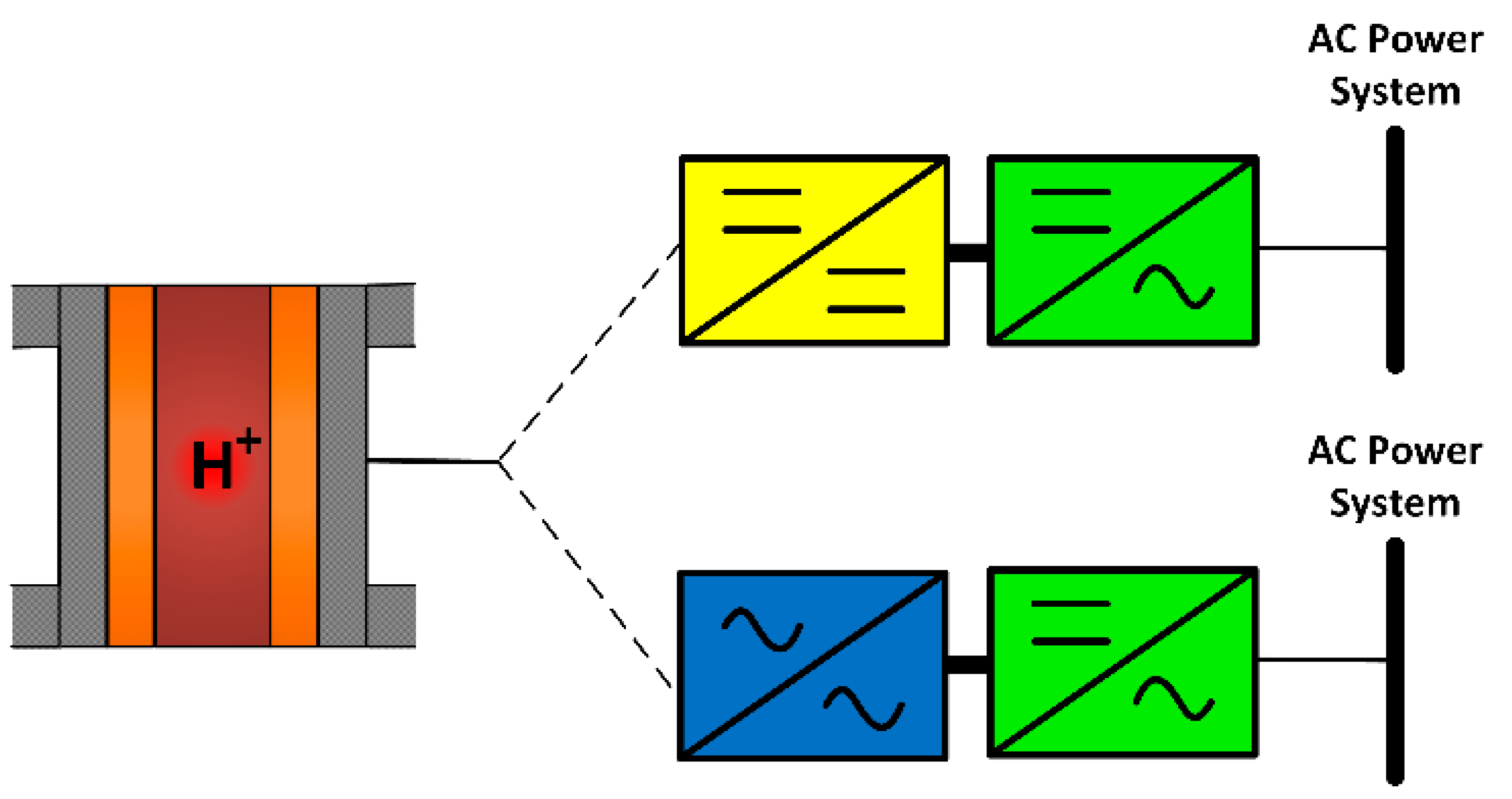
Figure 6. Main configurations of two-stage power converters for fuel cells.
6. Power Electronics and Small Hydro
Hydroelectric power plants are one of the oldest forms of electricity production, existing for more than a century. Over time, their technology has had little meaningful change, with the exception of the size and the power ratings. Recently, however, they have undergone positive changes due to power electronics. Previously, static converters only attended for rotor excitation and for high-voltage direct current (HVDC) transmission, but not as interface. With its advances and the expansion of small hydro, this picture has changed.
Conventional SM was, for a long time, the most used technology for hydroelectric plants. With the advent of modern small hydro, other types of generators have been chosen, as well as power electronics have gained more room for this DG technology. One of the reasons for this is that the flow variations have more impact on them than the traditional large-scale hydroelectric power stations. A significant benefit of these is the reservoir type, where water is stored by large natural or artificial dams and can be released for the controlled production of electricity. The small hydro power plants, in turn, are often of the run-of-river types, where accumulation is minimal or zero [39]. They depend, therefore, fundamentally, on the natural velocity of the waters and of the flows available at the moment.
Such specifications require devices that provide more appropriate solutions. The PM SM and the IM are preferred to solve these impasses. The first ones are coupled with fixed speed turbines and gearboxes, and they directly connect the system to the grid [40]. Using the fixed speed solution, variations in the water flow will provoke instability. In this way, variable speed solutions have enhanced operations for small hydro. The benefits are, beyond stability, higher efficiency, flexibility and even smaller flooded areas. In the mechanical part, the variable speed turbine, Francis, is pointed out as the best performance for small hydro. In electrical terms, the power electronics converters have a great importance. The two most common systems adopted are similar to those used in wind turbines. In one of them, the DFIG model, adapted for small hydro, configures a partially dependent power electronics system. In the other one, a totally dependent system, a back-to-back (AC-DC and DC-AC) converter, interweaves the power system with the generator, which can be the squirrel-cage IM, the conventional synchronous and the PM one [40][41]. Figure 7 shows these systems, with variable speed hydro turbines, and their respective electric machines and power electronics schemes.
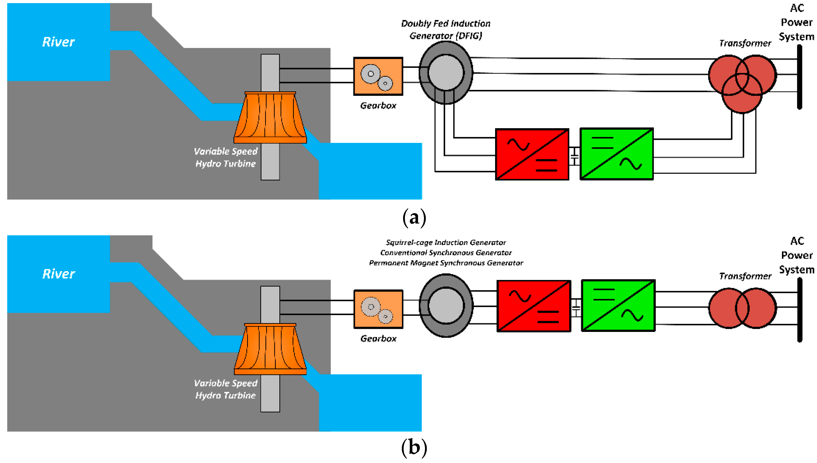
Figure 7. Variable speed small hydro categories: (a) partially dependent DFIG and (b) totally dependent of power electronics.
7. Power Electronics and Microturbines
Microturbines are a modern, small-scale electric power generation system technology. They can use several renewable sources, such as biomass [42], biodiesel fuel [43], waste-derived fuels [44], and can compound a combined heat-and-power (CHP) system [45][46]. They work similarly to the traditional turbines, producing electricity from burning some fuel, producing steam, which, in turn, is used to rotate an electrical machine. However, microturbines are smaller and more compact, since they are coupled to the generator in a single-shaft structure, eliminating the gearbox. The speed is, therefore, very high, reaching from 50,000 RPM to 120,000 RPM. For these reasons, a PM SM is the commonly chosen generator [47].
The output is AC, with high frequency, and the connection with the grid cannot be done directly, the use of a power electronics converter being an obligation for this task. To reach the grid frequency (60 or 50 Hz), a three-phase thyristor [47] or diode [48] rectifier can be connected to the output of the electric machine, followed by a voltage source inverter linked to the grid. Figure 8 exhibits this type of microturbine structure. More recently, however, the Pulse Width Modulation (PWM) rectifier has been a favorable choice, due to the reduction in the harmonic components produced that can elevate losses and augment the temperature of the generator [49].
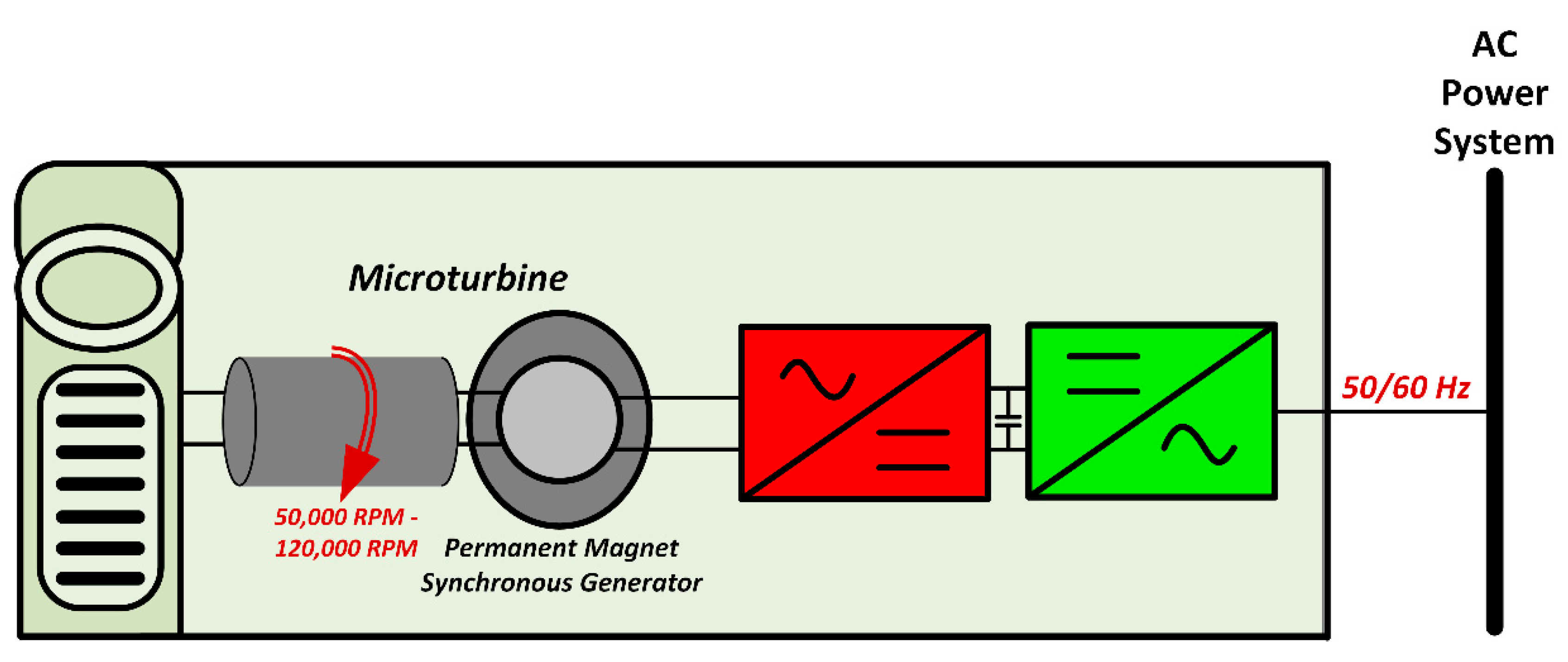
Figure 8. Microturbine structure with a rectifier followed by an inverter.
References
- Bose, B.K. Energy, environment, and advances in power electronics. IEEE Trans. Power Electron. 2000, 15, 688–701.
- Souza, M.E.T., Jr. Reflexões Acerca da Geração Distribuída e Suas Implicações no Sistema Elétrico, na Sociedade e no Meio Ambiente (Reflexions about Distributed Generation and Its Implications on the Power System, the Society and the Environment); Federal University of Uberlândia: Uberlândia, Brazil, 2018.
- Ellabban, O.; Abu-Rub, H.; Blaabjerg, F. Renewable energy resources: Current status, future prospects and their enabling technology. Renew. Sustain. Energy Rev. 2014, 39, 748–764.
- United Nations (UN). Transforming Our World: The 2030 Agenda for Sustainable Development. 2015. Available online: https://sdgs.un.org/2030agenda (accessed on 17 February 2022).
- International Renewable Energy Agency (IRENA). Renewable Capacity Statistics 2021. 2021. Available online: https://www.irena.org/publications/2021/March/Renewable-Capacity-Statistics-2021 (accessed on 17 February 2022).
- Mozina, C.J. The impact of distributed generation. PAC World 2008, 5, 18–25.
- Bollen, M.H.J.; Hassan, F. Integration of Distributed Generation in the Power System; John Wiley & Sons, Inc.: Hoboken, NJ, USA, 2011.
- IEEE Std 1547-2018 (Revision of IEEE Std 1547-2003); IEEE Standard for Interconnection and Interoperability of Distributed Energy Resources with Associated Electric Power Systems Interfaces. IEEE: Piscataway Township, NJ, USA, 2018.
- Kroposki, B.; Pink, C.; DeBlasio, R.; Thomas, H.; Simões, M.; Sen, P.K. Benefits of power electronic interfaces for distributed energy systems. IEEE Trans. Energy Convers. 2010, 25, 901–908.
- Islam, M.R.; Mekhilef, S.; Saidur, R. Progress and recent trends of wind energy technology. Renew. Sustain. Energy Rev. 2013, 21, 456–468.
- Blaabjerg, F.; Chen, Z.; Kjaer, S.B. Power electronics as efficient interface in dispersed power generation systems. IEEE Trans. Power Electron. 2004, 19, 1184–1194.
- Blaabjerg, F.; Iov, F.; Kerekes, T.; Teodorescu, R.; Ma, K. Power electronics—key technology for renewable energy systems. In Proceedings of the 2nd Power Electronics, Drive Systems and Technologies Conference, Tehran, Iran, 16–17 February 2011; pp. 445–466.
- Chen, Z.; Guerrero, J.M.; Blaabjerg, F. A review of the state of the art of power electronics for wind turbines. IEEE Trans. Power Electron. 2009, 24, 1859–1875.
- Blaabjerg, F.; Liserre, M.; Ma, K. Power electronics converters for wind turbine systems. IEEE Trans. Ind. Appl. 2011, 48, 708–719.
- Carrasco, J.M.; Franquelo, L.G.; Bialasiewicz, J.T.; Galván, E.; PortilloGuisado, R.C.; Prats, M.M.; Leon, J.I.; Moreno-Alfonso, N. Power-electronic systems for the grid integration of renewable energy sources: A survey. IEEE Trans. Ind. Electron. 2006, 53, 1002–1016.
- European Commission; Joint Research Centre (JRC); Villalba Pradas, A.; Telsnig, T.; Vázquez Hernández, C. JRC Wind Energy Status Report: Market, Technology and Regulatory Aspects of Wind Energy: 2016 Edition. 2018. Available online: https://op.europa.eu/en/publication-detail/-/publication/d131d668-0a13-11e7-8a35-01aa75ed71a1/language-en (accessed on 4 March 2022).
- REN21. Renewables 2020 Global Status Report. 2020. Available online: https://www.ren21.net/reports/global-status-report/ (accessed on 4 March 2022).
- Villalva, M.G.; Gazoli, J.R.; Ruppert Filho, E. Comprehensive approach to modeling and simulation of photovoltaic arrays. IEEE Trans. Power Electron. 2009, 24, 1198–1208.
- Kjaer, S.B.; Pedersen, J.K.; Blaabjerg, F. A review of single-phase grid-connected inverters for photovoltaic modules. IEEE Trans. Ind. Appl. 2005, 41, 1292–1306.
- Vinnikov, D.; Chub, A.; Liivik, E.; Kosenko, R.; Korkh, O. Solar optiverter—A novel hybrid approach to the photovoltaic module level power electronics. IEEE Trans. Ind. Electron. 2018, 66, 3869–3880.
- Kerekes, T.; Teodorescu, R.; Borup, U. Transformerless Photovoltaic Inverters Connected to the Grid. In Proceedings of the APEC 07—Twenty-Second Annual IEEE Applied Power Electronics Conference and Exposition, Anaheim, CA, USA, 25 February–1 March 2007; pp. 1733–1737.
- Melo, F.C.; Garcia, L.S.; de Freitas, L.C.; Coelho, E.A.; Farias, V.J.; de Freitas, L.C. Proposal of a photovoltaic AC-module with a single-stage transformerless grid-connected boost microinverter. IEEE Trans. Ind. Electron. 2017, 65, 2289–2301.
- Teodorescu, R.; Liserre, M.; Rodriguez, P. Grid Converters for Photovoltaic and Wind Power Systems; John Wiley & Sons: Hoboken, NJ, USA, 2011.
- Chen, W.; Yang, X.; Zhang, W.; Song, X. Leakage current calculation for PV inverter system based on a parasitic capacitor model. IEEE Trans. Power Electron. 2016, 31, 8205–8217.
- Ishaque, K.; Salam, Z. A review of maximum power point tracking techniques of PV system for uniform insolation and partial shading condition. Renew. Sustain. Energy Rev. 2013, 19, 475–488.
- Esram, T.; Chapman, P.L. Comparison of photovoltaic array maximum power point tracking techniques. IEEE Trans. Energy Convers. 2007, 22, 439–449.
- Eltawil, M.A.; Zhao, Z. MPPT techniques for photovoltaic applications. Renew. Sustain. Energy Rev. 2013, 25, 793–813.
- Reisi, A.R.; Moradi, M.H.; Jamasb, S. Classification and comparison of maximum power point tracking techniques for photovoltaic system: A review. Renew. Sustain. Energy Rev. 2013, 19, 433–443.
- Eltamaly, A.M. A novel musical chairs algorithm applied for MPPT of PV systems. Renew. Sustain. Energy Rev. 2021, 146, 111135.
- Kim, J.-C.; Huh, J.-H.; Ko, J.-S. Optimization design and test bed of fuzzy control rule base for PV system MPPT in micro grid. Sustainability 2020, 12, 3763.
- Eltamaly, A.M. A novel strategy for optimal PSO control parameters determination for PV energy systems. Sustainability 2021, 13, 1008.
- Raghavendra, K.V.G.; Zeb, K.; Muthusamy, A.; Krishna, T.N.V.; Kumar, S.V.S.; Kim, D.H.; Kim, M.; Cho, H.; Kim, H.J. A comprehensive review of DC–DC converter topologies and modulation strategies with recent advances in solar photovoltaic systems. Electronics 2020, 9, 31.
- Chaubey, R.; Sahu, S.; James, O.O.; Maity, S. A review on development of industrial processes and emerging techniques for production of hydrogen from renewable and sustainable sources. Renew. Sustain. Energy Rev. 2013, 23, 443–462.
- Cheng, K.W.E.; Sutanto, D.; Ho, Y.L.; Law, K.K. Exploring the power conditioning system for fuel cell. In Proceedings of the 2001 IEEE 32nd Annual Power Electronics Specialists Conference, Vancouver, BC, Canada, 17–21 June 2001; Volume 4, pp. 2197–2202.
- Sharaf, O.Z.; Orhan, M.F. An overview of fuel cell technology: Fundamentals and applications. Renew. Sustain. Energy Rev. 2014, 32, 810–853.
- Kirubakaran, A.; Jain, S.; Nema, R.K. A review on fuel cell technologies and power electronic interface. Renew. Sustain. Energy Rev. 2009, 13, 2430–2440.
- Das, V.; Padmanaban, S.; Venkitusamy, K.; Selvamuthukumaran, R.; Blaabjerg, F.; Siano, P. Recent advances and challenges of fuel cell based power system architectures and control–A review. Renew. Sustain. Energy Rev. 2017, 73, 10–18.
- Maciel, R.S.; de Freitas, L.C.; Coelho, E.A.A.; Vieira, J.B.; de Freitas, L.C.G. Front-end converter with integrated PFC and DC–DC functions for a fuel cell UPS with DSP-based control. IEEE Trans. Power Electron. 2014, 30, 4175–4188.
- Paish, O. Small hydro power: Technology and current status. Renew. Sustain. Energy Rev. 2002, 6, 537–556.
- Nababan, S.; Muljadi, E.; Blaabjerg, F. An overview of power topologies for micro-hydro turbines. In Proceedings of the 2012 3rd IEEE International Symposium on Power Electronics for Distributed Generation Systems (PEDG), Aalborg, Denmark, 25–28 June 2012; pp. 737–744.
- Singh, R.R.; Chelliah, T.R.; Agarwal, P. Power electronics in hydro electric energy systems–A review. Renew. Sustain. Energy Rev. 2014, 32, 944–959.
- Jurado, F.; Cano, A.; Carpio, J. Biomass based micro-turbine plant and distribution network stability. Energy Convers. Manag. 2004, 45, 2713–2727.
- Nascimento, M.A.; Lora, E.S.; Corrêa, P.S.; Andrade, R.V.; Rendon, M.A.; Venturini, O.J.; Ramirez, G.A. Biodiesel fuel in diesel micro-turbine engines: Modelling and experimental evaluation. Energy 2008, 33, 233–240.
- Seljak, T.; Katrašnik, T. Designing the microturbine engine for waste-derived fuels. Waste Manag. 2016, 47, 299–310.
- Dong, L.; Liu, H.; Riffat, S. Development of small-scale and micro-scale biomass-fuelled CHP systems–A literature review. Appl. Therm. Eng. 2009, 29, 2119–2126.
- Karellas, S.; Karl, J.; Kakaras, E. An innovative biomass gasification process and its coupling with microturbine and fuel cell systems. Energy 2008, 33, 284–291.
- Bertani, A.; Bossi, C.; Fornari, F.; Massucco, S.; Spelta, S.; Tivegna, F. A microturbine generation system for grid connected and islanding operation. In Proceedings of the IEEE PES Power Systems Conference and Exposition, New York, NY, USA, 10–13 October 2004; Volume 1, pp. 360–365.
- Lasseter, R.H. Dynamic models for micro-turbines and fuel cells. In Proceedings of the 2001 Power Engineering Society Summer Meeting. Conference Proceedings, Vancouver, BC, Canada, 15–19 July 2001; Volume 2, pp. 761–766.
- Khaburi, D.A.; Nazempour, A. Design and simulation of a PWM rectifier connected to a PM generator of micro turbine unit. Sci. Iran. 2012, 19, 820–828.
More
Information
Subjects:
Engineering, Electrical & Electronic
Contributor
MDPI registered users' name will be linked to their SciProfiles pages. To register with us, please refer to https://encyclopedia.pub/register
:
View Times:
4.5K
Revisions:
2 times
(View History)
Update Date:
23 Mar 2022
Table of Contents


Notice
You are not a member of the advisory board for this topic. If you want to update advisory board member profile, please contact office@encyclopedia.pub.
OK
Confirm
Only members of the Encyclopedia advisory board for this topic are allowed to note entries. Would you like to become an advisory board member of the Encyclopedia?
Yes
No
${ textCharacter }/${ maxCharacter }
Submit
Cancel
Back
Comments
${ item }
|
${ item.createdUser.fullName }
${ item.createdAt }
${ item.vote }
${ item.reply }
Delete
${ reply.createdUser.fullName }
${ reply.createdAt }
${ reply.vote }
Delete
There is no reply to this comment~
${ item.replyTextCharacter }/${ item.replyMaxCharacter }
Submit
Cancel
More
No more~
There is no comment~
${ textCharacter }/${ maxCharacter }
Submit
Cancel
${ selectedItem.replyTextCharacter }/${ selectedItem.replyMaxCharacter }
Submit
Cancel
Confirm
Are you sure to Delete?
Yes
No