Wind turbines (WTs) are large devices utilized to convert the wind's kinetic energy into electricity. There are several different typologies of WTs, the most common type being the so-called Horizontal Axis Wind Turbine (HAWT) systems. In this configuration, the rotation axis of the rotor is parallel to the ground. Specific attention must be paid to the orientation with respect to the wind direction, which is different from other types of wind turbines such as those with a vertical axis (VAWT), whose orientation is independent of the prevailing wind direction. For HAWT, the three-bladed upwind configuration is the most common one, with the rotor facing the incoming wind. WTs can be deployed both on- or offshore and have very different blade lengths, which result in different sizes (especially regarding the tower height) and power output. Due to fatigue and exposure to outdoor elements, WT monitoring and diagnostics are strictly needed to reduce structural and mechanical failure and achieve cost-effective energy production. This requires both the Structural Health Monitoring of the WTs load-bearing components (tower, blades, foundations, etc) and the Condition Monitoring of their mechanical parts (gearbox, generator, etc).
1. Wind Turbines: Structural and Mechanical Components
There are several different typologies of “wind turbines”, the most common type being the so-called Horizontal Axis Wind Turbine (HAWT) systems. In this configuration, the rotation axis of the rotor is parallel to the ground. Specific attention must be paid to the orientation with respect to the wind direction, which is different from other types of wind turbines such as those with a vertical axis, whose orientation is independent of the prevailing wind direction. The upwind configuration is the most common one, with the rotor facing the incoming wind.
here, the focus will be on HAWT only since they represent the most common and conventional typology. The term “wind turbine” will therefore be used exclusively for this specific device hereinafter. In more detail, the only structural configuration of interest will be the classic towered HAWT, with one or more blades (usually three). Both on- and offshore turbines are included. Except for small wind turbines for private on- or off-grid energy production, any tower size and blade length are considered.
From an engineering perspective, any wind turbine is made up of:
- (i) static, load-bearing components;
- (ii) moving/rotating parts, needed to harness the wind’s kinetic energy and turn it into electricity.
The elements in (i) are mainly part of the support structure, with the important exception of the WT blades. The components of (ii) can be further divided between slowly rotating elements (blades) and high-speed rotating mechanisms. These latter ones are all included in the rotor–nacelle assembly on top of this support structure.
These distinctions are essential since the blades and the support structure are fields of application for Structural Health Monitoring (SHM), while Condition Monitoring (CM), according to the common definition of the term, deals with machinery and rapidly moving components such as gears and bearings in the gearbox and generator.
Indeed, elements in both (i) and (ii) are subject to naturally occurring use and consumption and, therefore, can develop structural damage in the long run. Damage in the external structure will cause (partial and localized or global) collapse, while damage in the internal mechanisms will cause faults, disruption in the energy production, and potentially fire, explosions, oil leakage, or other events.
2. Components under Structural Health Monitoring
2.1. The Tower
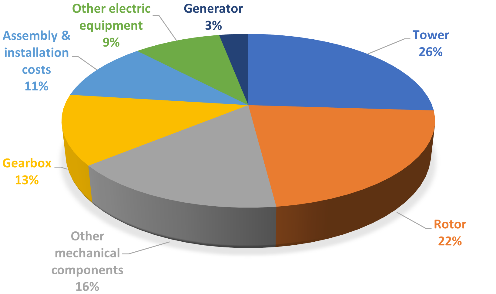
The tower is the main component of the support structure. Apart from foundation costs (which vary noticeably for on- and offshore structures), its cost can be up to one-fourth of the total
[1] (
Figure 1).
The main parameter of the tower is its height. This is typically about 1.5 times the rotor diameter; generally, it is never lower than 20 m and can reach up to 150 m or more (for 10–12 MW outputs). In absolute terms, the higher the tower, the better the wind conditions in terms of intensity and constancy.
Conventionally, the WT tower can be lattice or tubular. This second design choice has been more common since the mid-1980s. In this case, the tower is made of thin-walled steel conical parts of varying diameters and diameter-to-wall thickness ratios. These offer a practical and safer way for the survey teams to access the nacelle. Moreover, in comparison to lattice structures, there are fewer bolted joints to inspect and maintain. The tower diameter (maximum at its basis and minimum at its top) increases with the tower height; e.g., a typical 50 m-tall HAWT will have a diameter ranging from 3.5 m to 0.4 m
[2].
From a vibrational and SHM perspective, the stiffness of the tower is the main parameter to be taken into consideration in evaluating the global dynamics of WTs due to the possibility of coupled vibrations between the tower and the rotor.
Figure 1. Estimated costs of a HAWT, as a percentage of the total and excluding foundations.
2.2. The Substructure
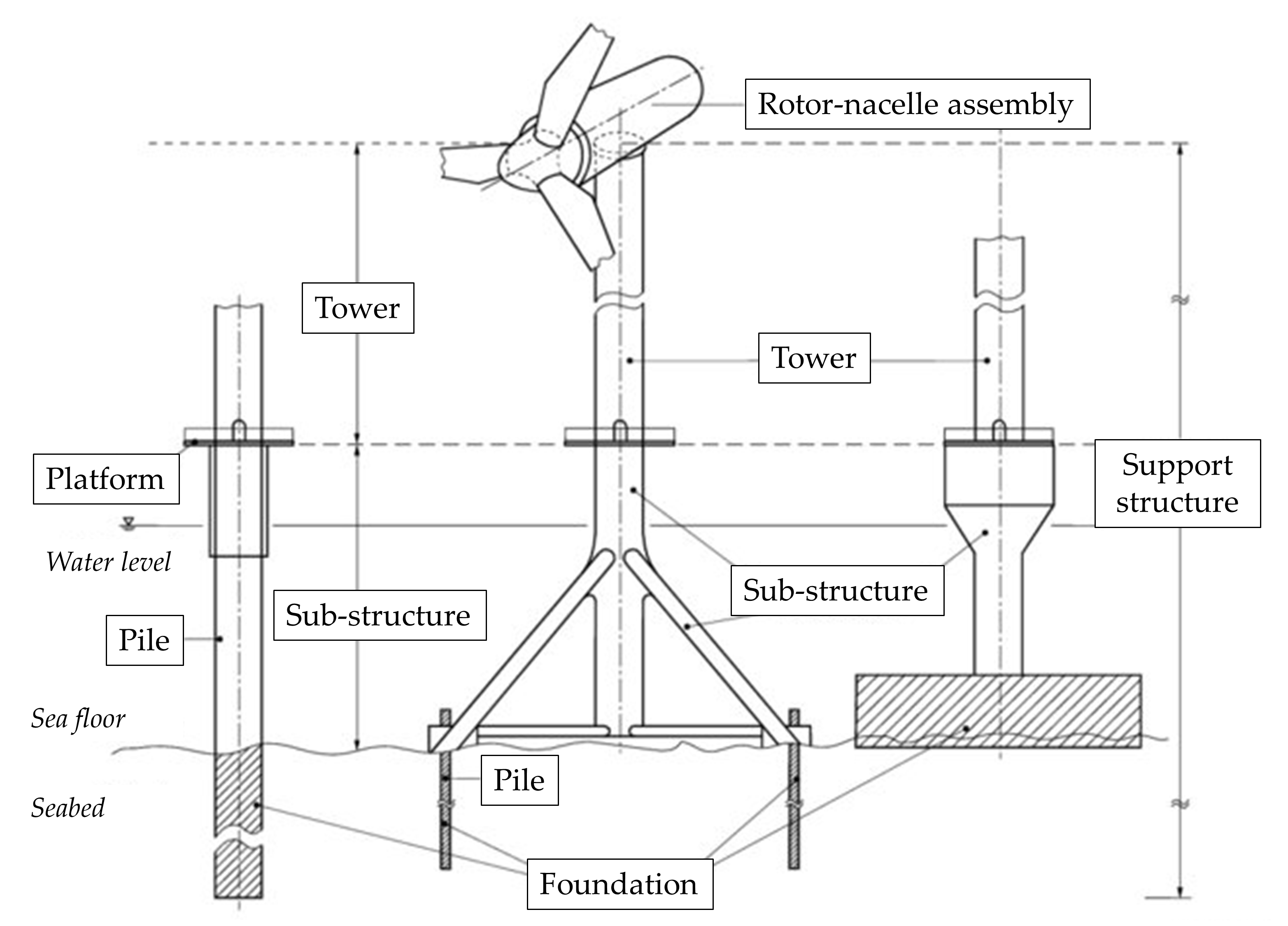
Offshore HAWTs, differently from their onshore counterparts, include a further group of structural elements, which are included below the platform and above the seafloor (Figure 2). These components are particularly at risk due to their location underwater or—even worse—in the splash zone, immediately above/below the mean water level and highly subject to corrosion. Furthermore, being submerged, they cannot easily be visually inspected if not using divers or manned/unmanned underwater inspection robots. They are also subject to marine growth and other potentially damaging environmental conditions such as wave, tidal, and current forces.
Figure 2. Structural components of a fixed offshore HAWT according to IEC 61400-3-1.
2.3. The Foundations
On- and offshore foundations differ sensibly. However, in both cases, the choice of the specific structural design depends on the location and site conditions. For example, the quality and strength of the soil are the main determinants affecting the size and shape of onshore foundations, while the depth of the water and the distance from the coast are the key factors for offshore turbines.
For onshore installations, both surface (shallow) and deep foundations are frequently used. In the wind farms dating back to the 1990s, square foundations with a constant thickness were commonly utilized. This solution, however, can lead to the formation of localized damage. Hexagonal and octagonal shapes subsequently became more common, even with variable thicknesses. The most modern designs use circular shapes, which allow the reinforcing bars to be positioned more homogeneously. This ensures a better dispersion of the forces induced by the soil–structure (or soil–pile–structure) interactions.
The foundation design, construction, and monitoring in offshore wind farms are more complex and challenging. The costs are much higher as well, absorbing a large percentage of the total expense of an offshore wind turbine. Specifically, Ref.
[3] mentioned the offshore foundation costs to be 35% of the total project expenses. Refs.
[3][4] estimated a cost from 352 EUR/kW (
~19.6% of the total construction cost) for a water depth between 10 and 20 m, up to 900 EUR/kW (
~35.8%) for transitional waters (40 to 50 m deep). For smaller HAWT closer to the coast (1–2 MW, with A water depth <30 m), monopile foundations are often encountered. Jacket/tripod substructures are more frequent between 25 and 50 m and for larger structures (2–5 MW)
[5]. For deep waters (50–120 m and beyond), floating structures, anchored to the seafloor, are preferable. Conversely, gravity-based foundations (to the right side in
Figure 2) can be found for offshore installations in very shallow waters but they are not widely used
[3].
2.4. The Rotor
The rotor is a crucial component of the wind turbine. Indeed, it is the most expensive mechanical component, up to circa one-fifth of the total cost
[6]. Its design is one of the most critical and delicate phases, especially in terms of expected performances; indeed, the economic feasibility of the whole WT depends essentially on the correct sizing and design of this component.
The rotor consists of the blades and the hub from which they branch off. Conventionally, the rotor can be single-, double-, or three-bladed. The most common turbines include three blades arranged at 120° from each other; this is generally considered the optimal design.
The length of the blades determines the capability to convert high wind speed to low rotational speed and finally to electrical energy. As mentioned before, the diameter of the rotor governs the tower height and thus the overall size of the structure, including the foundations. Indeed, a larger rotor will produce a consequent increase in the energy produced but, on the other hand, will require a wider tower cross-section and more massive and/or deep foundations, thus increasing the construction costs.
For monitoring purposes, a “smart rotor” system should include several sensors (accelerometers, strain gauges, pitot tubes, pressure tabs, etc.), embedded and distributed along the blades' whole length
[7].
2.5. The Blades
WT blades are generally made of glass or carbon fibre reinforced polymeric (GFRP and CFRP) materials. E-glass fibres are particularly used as the main reinforcement in the composite material.
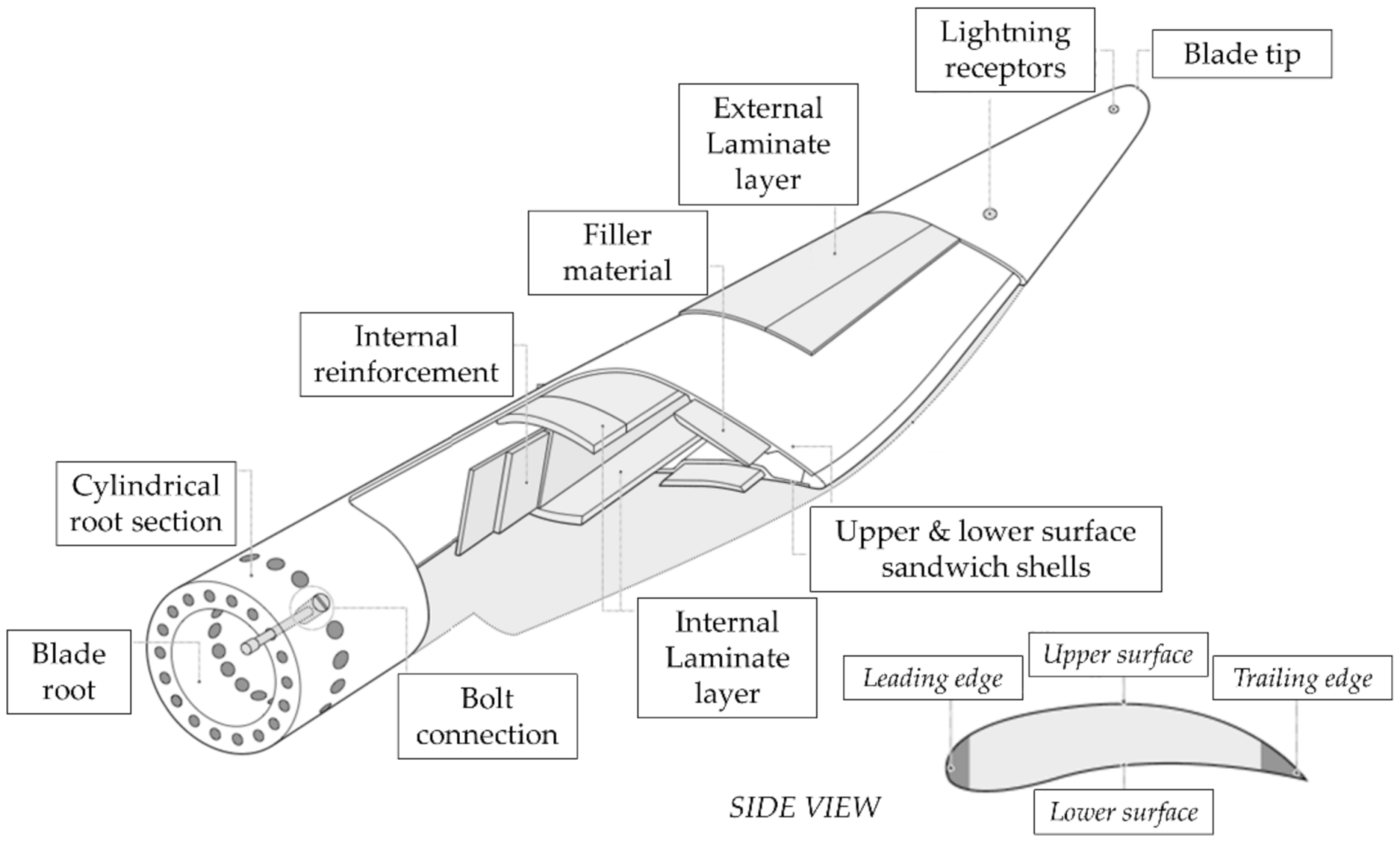
The blade design is actually quite complex, with several different components and materials as pictorially described in
Figure 3. This complexity makes them particularly susceptible to manufacturing defects, which indeed were estimated in Ref.
[8] to account for
~ 51% of all blade damages (with debonding and voids in skin core being the most common defects at 20% and 18%, respectively).
Figure 3. Key components of a typical wind turbine blade. The upper and lower surfaces are also known as the suction (or windward) and pressure (or lee) sides, respectively. The blade root bolt connection shown here is a classic T-bolt type.
From a geometric perspective, the cross-section profile varies from root to tip, often also rotating around its main axis; all these aerodynamical aspects of their airfoil design characterize the blade lift-to-drag ratio and, by consequence, the wind-to-rotor efficiency. The internal reinforcements may include different sorts of load-carrying structural elements, such as shear webs, closed shells, box spars, or other geometries. These design choices affect the space available for the maintenance workers to operate.
As briefly mentioned earlier, the structural integrity of WT blades is of the foremost importance, due to the potential impacts of fully or partially detached blades with neighbouring structures.
3. Components under Condition Monitoring
3.1. Drive Train (and Other Components Inside the Nacelle)
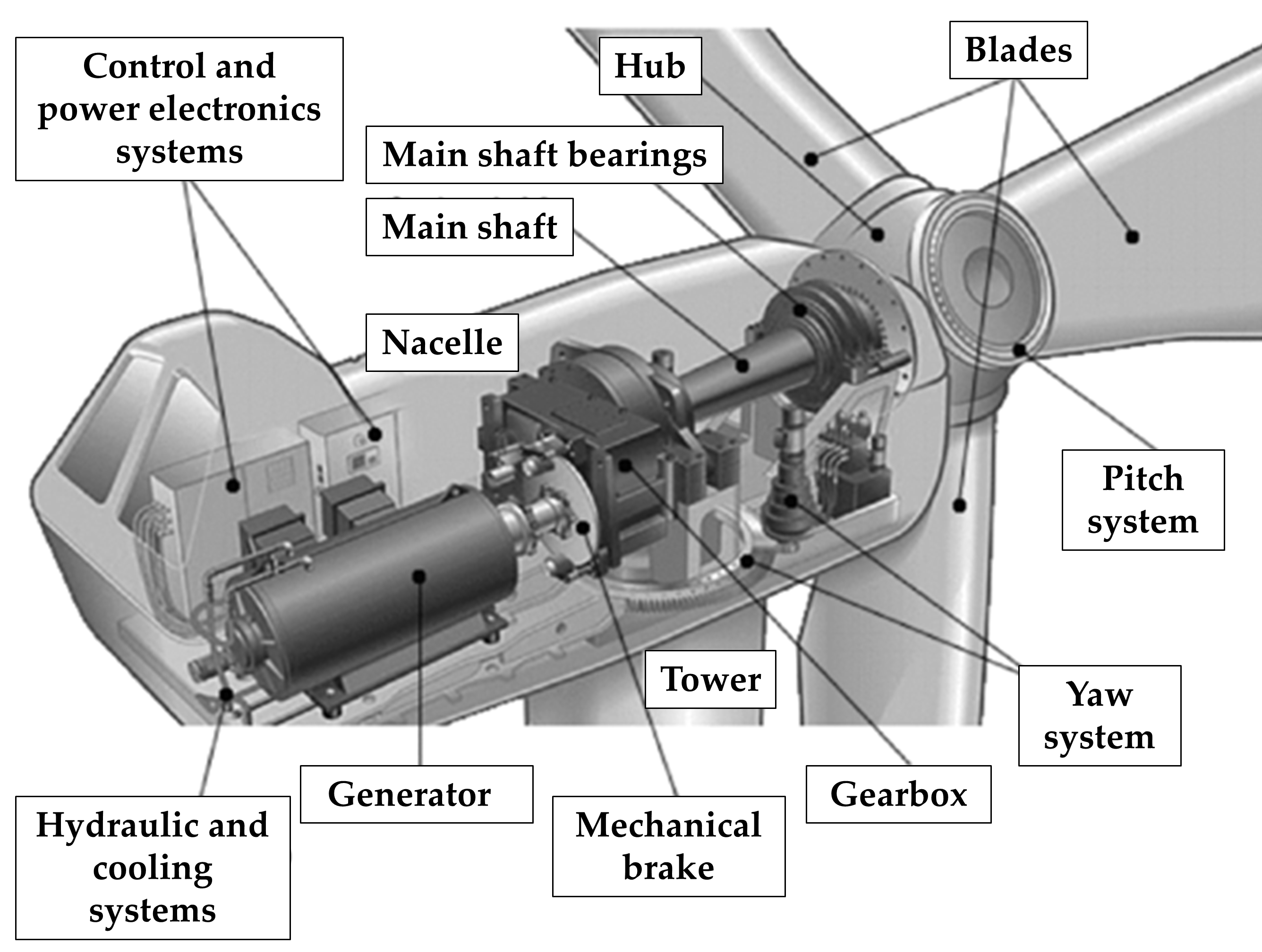
Positioned on the top of the tower, the nacelle is a cover housing, intended to shelter all the mechanical and electrical components installed inside from the external environment. These mechanisms include (for a conventional HAWT) the gearbox, rotor shaft, brake, and generator, all assembled together (
Figure 4, adapted from Ref.
[9]). These pieces are necessary for energy conversion and represent roughly between one-third and half of the HAWT total cost on their own
[6].
Figure 4. Mechanical and electrical components inside the nacelle of a conventional HAWT.
Other mechanisms included in the tower and the nacelle are, to name a few, the rotor yaw system and the control and power electronics systems.
The yaw system is responsible for the orientation of the nacelle–rotor assembly towards the wind, rotating 360° around the vertical axis. The control and power electronics systems are tools of fundamental importance to control the operation of the machine, manage the supply of electricity, and stop the system beyond certain wind speeds for safety reasons due to the excessive heat (generated by the friction of the rotor on the axis) and/or mechanical stresses. Therefore, they maximize the life of the system by ensuring the limitation of the fatigue of all components (fatigue that can result due to changes in wind speed and direction, the presence of turbulence, shutdown, and start-up cycles of the turbine, etc.). These systems include speed, position, temperature, and voltage sensors; mechanical or electrical controllers; actuators; valves; switches; microprocessors; and many other components.
3.2. The Gearbox
The main rotating machinery in a typical HAWT is the gearbox, which is also the element most prone to mechanical faults. Therefore, it is the component of major interest for Condition Monitoring.
Gearboxes in HAWTs are generally multi-stage, with one or more sequential planetary stages, followed by one or more parallel stages (i.e., helical gears). The rationale is that the speed of the rotor axis (in the order of magnitude of tens of revolutions per minute, rpm, depending on the wind) is not sufficient for the generator to produce electricity cost-efficiently.
In the typical drive train configuration, the gearbox acts as a rotation speed multiplier, connecting a low-rpm, high-torque shaft on the rotor side (known as the input, slow, or main shaft) to a high-speed (output) shaft on the generator side
[10]. The support bearings, mechanical brake, and rotating parts of the generator make up the rest of this common configuration. This can increase the revolutions per minute from 12–30 up to 1200–1800. The efficiency of the gearbox is also linked to the lubricant conditions. These refer to both the oil cleanliness in terms of particle content and the oil viscosity (which influences the thickness of the oil film in the gears and bearings).
3.3. The Generator
Located behind the gearbox and driven by the high-speed shaft, the electric generator accommodates the mechanical and electrical components needed to convert the incoming rotation into electricity. In comparison to other generators, the ones in use for wind power need to adapt to a fluctuating mechanical power (torque) source. Furthermore, for wind turbines directly or indirectly connected to local or national grids, synchronous or asynchronous alternators are required to produce electrical energy at the grid frequency (generally 50 Hz or 60 Hz, depending on the national standards). Traditionally, squirrel-cage induction machines and synchronous machines have been used for small scale WTs; doubly-fed induction generators are considered the dominant technology for larger models
[11]. Other technologies include the permanent magnet, switched reluctance, and high-temperature superconducting generators. A comparative analysis of the benefits and limitations of some options can be found in Ref.
[12].
4. Incidence and Main Causes of Structural Collapse
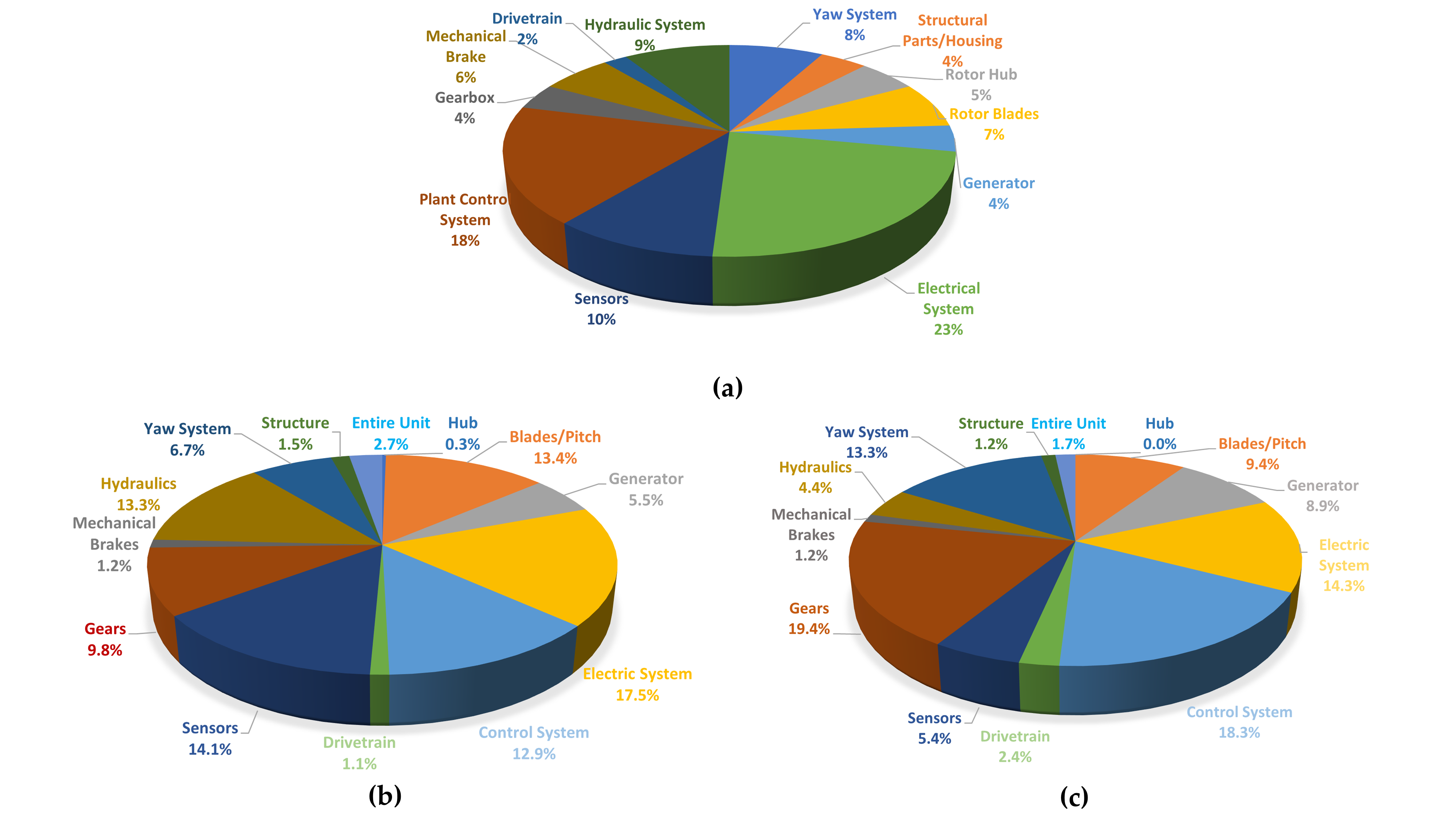
In general terms, structural components are much less likely statistically to be subject to damage and failure than mechanical and electrical components. This is shown in detail in the statistics in
Figure 5 [13][14]. For the tower, typical failure mechanisms are caused by bolt loosening induced by dynamic loads
[15]. However, as can be seen from
Figure 5b, WT blades are the structural elements most affected by damage. This is due to their higher complexity, particular materials, and exposition to strong dynamic loads. The static load-carrying elements (tower structure and substructure, plus foundations) are considered to be less damage-prone. Among the many potential causes of their catastrophic collapse, the structure of the metallic tower is subject to all the classic risks of thin-walled shells, e.g., buckling. Even concrete-made towers may suffer total collapse due to damage at the base (at least one case was reported in Germany in 2000
[16]).
Figure 5. Damage and failure statistics. (a) Percentage of unforeseen malfunctions as recorded in Germany for 1500 wind turbines. Based on data retrieved from Ref. , collected over 15 years (34,582 events). (b,c) percentage distribution of the total number of failures and downtimes for WTs (in the same order). Based on data retrieved from Ref. , collected from several sources in Sweden, totalling about 600 WTs from 2000 to 2004 (1202 events, 156,202 h). The nomenclature used in the original sources is reproduced for all charts.
During their operational lifespan (commonly 20–25 years), the WT blades are subject to rapidly changing dynamic loads, which can cause fatigue damage
[17][18], plus other environmental conditions such as rain, humidity, and abrasive wind-carried dust or other kinds of particulate matter. Even the simple uninterrupted exposition to sun-radiated ultraviolet rays causes durability issues in the long term. All these eventualities might cause surface damage and/or corrosion.
Moreover, the blades can be hit by larger foreign objects, such as hailstone and bird strikes, and (commonly) by lightning. These two latter factors account (in the same order) for 16% and 20% of the total damage causes according to Ref.
[8], making them the most common causes after manufacturing defects. It is estimated that one-third of all damages on blades happens during storm events
[19].
The blade tip and trailing edge (refer to
Figure 3) are generally designed and shaped to minimize aerodynamic noise, which makes them thin and particularly prone to the occurrence of mechanical damage. A full-scale static test showed that a 40 m-long E-glass/epoxy composite WT blade can bear tip deflections up to 11 m under flap-wise loading before structural collapse
[20]. This large flexibility, however, may cause the blade tip to hit the HAWT tower under exceptional wind conditions. Due to its cross-section, the blade is much stiffer edge-wise. In conclusion, seven categories of damage are considered as the most common ones in composite blades; these are reported in
Table 1.
Table 1. Typical damage typologies in WT blades, according to Refs.
[21][22].
| Damage Type |
Description |
| #1 |
Damage formation and growth in the adhesive layer joining the skin and main spar flanges (skin/adhesive debonding and/or the main spar/adhesive layer debonding). |
| #2 |
Damage formation and growth in the adhesive layer joining the up- and downwind skins along leading and/or trailing edges (adhesive joint failure between skins). |
| #3 |
Damage formation and growth at the interface between the face and core in the sandwich panels in skins and the main spar web (sandwich panel face/core debonding). |
| #4 |
Internal damage formation and growth in laminates in the skin and/or main spar flanges, under a tensile or compression load (delamination driven by a tensional or a buckling load). |
| #5 |
Splitting and fracture of separate fibres in the laminates of the skin and main spar (fibre failure in tension; laminate failure in compression). |
| #6 |
Buckling of the skin due to damage formation and growth in the bond between the skin and main spar under a compressive load. * |
| #7 |
Formation and growth of cracks in the gel coat; debonding of the gel-coat from the skin (gelcoat cracking and gel-coat/skin debonding). |
5. The Incidence and Main Causes of Mechanical Failure
Recalling Figures 5b and 5c, one can see that the mechanical failures (including brakes, gears, drive train, and generator) are preponderant in terms of both total failures and downtime. For this reason, the majority of scientific research focuses on the CM of these components housed inside the nacelle.
In this context, the concept of the “failure rate” is generally applied. The standard time-scheduled maintenance, therefore, should follow the classic bathtub curve, focusing on early-stage monitoring (to assess “infant mortality”, due to defective components) and in the long run, where wear out failures start to become predominant. During its life cycle, any WT is however subject to the random occurrence of unexpected faults; this represents a statistical constant along time. In general, gearbox failures happen slightly more frequently due to late wear out failures compared to early infant mortality
[24]. A study over a 13-year timeframe showed a failure rate from 0.10 to 0.15 mechanical failure/turbine/year for land-based European WTs
[25].
Bearings are, arguably, the most critical component of the gearbox. A 2013 report from the U.S. National Renewable Energy Laboratory (NREL)
[26] estimated that about 70% of all gearbox failures are due to bearing failures. More specifically, the bearing life of the parallel stages is generally considered to be very high, in many cases over 1 million hours
[27], even if bearing failures at this stage are nevertheless not uncommon (see, e.g., Ref.
[28]). On the other hand, bearings in the planetary stages often do not fulfil their design lifespan
[27]. This has also been assessed in many experimental campaigns
[28] and it is quite understandable due to the large torque applied at the planetary gear stages. The reliability and durability of these bearings have always been considered one of the major issues for WTs
[29]. Many failures are observed in the bearing inner rings of the planetary stages since these are exposed to
~5 times more high load cycles than the outer rings
[27].
Table 2 reports a brief description of the most common bearing failure typologies, according to the nomenclature reported in Ref.
[30].
Table 2. Typical damage typologies in bearings, according to Ref.
[30].
| Damage Type |
Description |
Possible causes |
| Flaking |
Creation of regions with a rough and coarse texture due to the splitting off of small pieces from the raceway surface. |
Rolling fatigue, caused in turn by excessive load, misalignment, poor lubrification, water or debris inclusions, unsuitable bearing clearance, unevenness in housing rigidity, rust, corrosion pits, dents. |
| Peeling |
Light wear and dull spots on the surface, with micrometric cracks and minor flaking. |
Poor or unsuitable lubricant, debris intrusion in the lubricant. |
| Scoring |
Straight lines on the surface, circumferentially on the raceway surface. |
Generated by accumulated small seizures, caused in turn by sliding under improper lubrication or excessive/improper loads and conditions (shaft bending, the inclination of inner and outer rings, etc). |
| Smearing |
Surface damage, with the formation of rough and partially melted material. |
Generated by accumulated small seizures between bearing components, caused in turn by oil film rupture (because of poor/improper lubrication or high speeds with very light loads). |
| Fracture |
Small pieces broke off due to shock loads or stress accumulation. |
Impacts during mounting/dismounting, excessive loads, progression of surface cracks. |
| Cracks |
Formation of surface cracks on the raceway rings and/or rolling elements. |
Excessive loads, progression of flaking damage, creep-induced heating, inappropriate shaft (e.g., poor taper angle). |
| Cage damage |
Cage deformation, fracture, and/or wear (considering the cage guide surface, pocket surface, and cage pillars). |
Excessive speed, sudden acceleration/deceleration, high temperature, poor lubrication, excessive vibrations, bearing misalignment. |
| Denting |
Small dents on the surface of raceway rings or rolling elements. |
Caused by metallic particles or other very small debris caught in the surface during rolling. |
| Pitting |
Pitted surface on the raceway rings or rolling elements. |
Poor lubricant, debris in the lubricant, or exposure to moisture. |
| Wear |
Surface deterioration on the raceway rings, rolling elements, cage pockets, and/or roller end faces. |
Sliding friction between two surfaces, caused in turn by an irregular motion of the rolling elements, poor lubrication, debris intrusions in the lubricant, or as a progression from chemical or electrical corrosion. |
| Fretting |
Corrosion at the contact area between the raceway ring and the rolling elements. It may happen at regular roller pitch intervals. |
Repeated sliding on the fitting surface. |
| False brinelling |
Hollow spots that resemble Brinell dents. |
Caused by wear, induced in turn by vibration and swaying at the contact points between the raceway and the rolling elements, especially with poor lubrication. |
| Creep |
Shiny appearance on the fitting surface, potentially coupled with scoring and wear. |
Relative slipping at the fitting surfaces, due to a loose fit or insufficient sleeve tightening. |
| Seizure |
Softened, deformed, and/or melt material in the raceway rings, rolling elements, or cage. |
Excessive load, speed, shaft bending, poor housing or lubrication, small internal clearance. |
| Electrical corrosion |
Corrugations resulting from locally melted material. |
Melting by arcing, induced by the passage of electric currents. In turn, these are induced by the electrical potential between the inner and the outer rings. |
| Pit corrosion |
Pits on the surface of raceway rings or rolling elements due to chemical corrosion. |
Entry of corrosive gas or liquid, improper lubricant, moisture, high humidity, improper handling and storage conditions. |
| Mounting flaws |
Scratches on the surface of raceway rings or rolling elements caused by mounting/dismounting. |
Incorrect mounting/dismounting (impulse loads, the inclination of inner or outer rings, etc). |
| Discolouration |
Discolouration of the cage, rolling elements, or raceway rings. |
Poor lubrication and/or high temperature. |
In general terms, the gearbox gears' reliability is often lower than expected; their capability to fulfil their design life depends largely on the manufacturer’s design, tooth profile, and material quality
[27]. Surface fatigue cracks and tooth bending fatigue are among the most common causes
[27]. Outside of the gearbox, the main shaft bearings are considered to be much less critical and are generally capable of fulfilling their design life
[31].
The generator presents some rotating components that require CM as well. This can be performed with vibration-based inspection (VBI) and signal processing approaches (two examples are reported in Refs.
[32][33]) or using alternative methods such as temperature trend analysis
[34]. However, one should remember that, apart from purely mechanical failures, generators are (obviously) at risk of the failure of electrical materials
[35].
In conclusion, Table 3 reports the main causes of mechanical failure according to the scientific literature.
Table 3. Typical failure modes in wind turbine mechanical components, according to Ref.
[36].
| Mechanical Component |
Common Failure Modes |
| Gearbox and drive train |
Gear tooth damages, high- or low-speed shafts faults, gearbox bearing failures. |
| Generator |
Generator stator failure, generator rotor failure, generator bearing failure. |
| Main bearing |
Bearing failure, bearing rubs, bearing looseness |
| Pitch gears |
Pitch Gear tooth damages. |
| Yaw gears |
Yaw Gear tooth damages. |
6. Survey and Maintenance Policy for Offshore Wind Farms
Due to the great logistic complexity and high Operation and Maintenance (O&M) costs of WT maintenance, a brief discussion about the different strategies commonly applied for on- and offshore wind farms is needed.
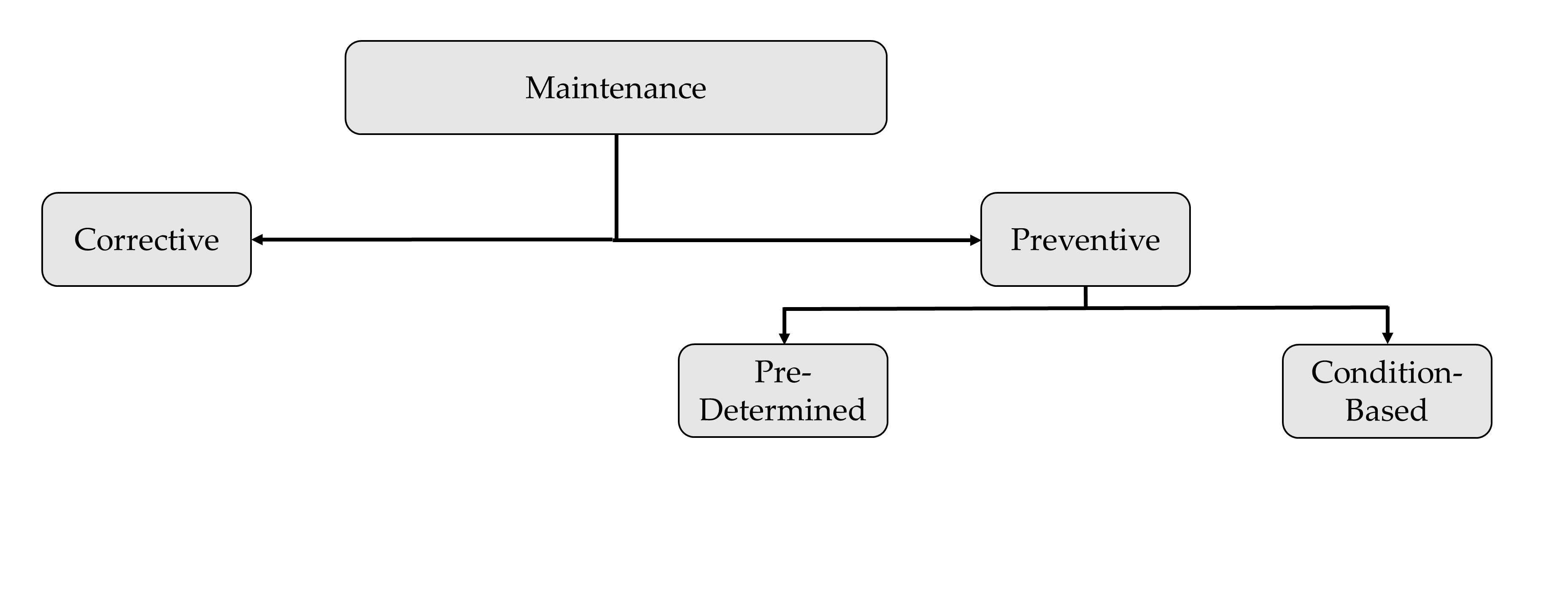
“Corrective” or “reactive” maintenance is, by definition, performed after failure detection, aiming at the restoration of an asset to a condition in which it can perform its intended function. It is both unscheduled and unplanned. Thus, corrective maintenance is often unavoidable, with the maintenance teams having to respond to equipment breakdown or failure immediately with little to no pre-alarm and often without a totally clear understanding of the exact cause of damage/failure. “Preventive” maintenance, on the contrary, aims to carry out an overhaul, replacement, or repair before the component fails, in a pre-planned, predictable fashion. This can help to reduce downtimes while also improving efficient resource planning.
Preventive maintenance can be further divided into pre-determined (time-scheduled) and predictive (condition-based) maintenance. This scheme is the one currently set by the current European standard, as dictated by the norm EN 13306:2017 (depicted in Figure 6).
Figure 6. Maintenance strategies according to EN 13306:2017.
The current trend in the wind industry is to transition from time-scheduled to condition-based monitoring, using embedded sensors and continuous, permanent monitoring systems to detect early signs of anomalies at a global level. This is mostly achieved through vibration-based signal processing, SCADA data analysis, and statistical pattern recognition, applying Artificial Intelligence strategies (mainly Machine Learning and Artificial Neural Networks).
However, once an anomaly is detected (or even localized) at a global level, on-site maintenance is still required for in-depth, localized analysis. Therefore, local Non-Destructive Evaluation (NDE) and global vibrational approaches are not mutually exclusive. On the contrary, they both allow fast and cost-efficient maintenance planning. This concept is a key component of the “Intelligent Maintenance” framework, based on a globally optimum trade-off between prevention and repair costs
[9].
For the economic and logistic reasons mentioned before, the issue of proper maintenance planning is even more prominent for offshore installations. Table 4 reports the main factors that affect the selection of the maintenance and survey strategy for offshore wind farms, according to selected authors from the recent scientific literature.
Table 4. Main factors influencing the choice of the maintenance strategy for offshore wind farms.
| Study |
Year |
Mentioned Factors |
| Henderson et al. [37] |
2003 |
Accessibility of the offshore platform and reliability of the monitoring strategy. |
| Nielsen et al. [38] |
2011 |
Weather conditions, total power generation, repair strategies, transportation strategies. |
| Dinwoodie et al. [39] |
2012 |
Repair time, wave height, wind speed, number of wind turbines in the wind farm, ship availability, availability of spare parts stocks. |
| Scheu et al. [40] |
2012 |
Expected typologies of component failures, ship fleet size, ship type, travel time, number of maintenance workers on staff. |
| Besnard et al. [41] |
2013 |
Location of accommodation facilities for maintenance staff, vessels for the transfer of crew (type and number), availability of helicopters, organization of work shifts, management of spare parts stocks, technical support, availability of cranes (purchase or contract), environmental conditions (depending on weather and season), economic parameters (electricity prices, ship rental costs). |
| Halvorsen-Weare et al. [42] |
2013 |
Investment costs, ship costs (fixed and variable costs), failure probability, downtime costs, meteorological data. |
| Hofmann & Sperstad [43] |
2013 |
Weather conditions (including uncertainty), breakdown rates, electricity price, ship price (costs, fleet composition, type, quantity), workers (shift length, quantity), location of the maintenance base of operations. |
| Perveen et al. [44] |
2014 |
Protection methodologies, occurrence of cable and component failures, repair strategy, wind speed predictions, and condition monitoring systems. |
| Endrerud et al. [45] |
2015 |
Weather conditions, ships (availability, operating limits, costs), availability of maintenance technicians, repair times, wind farm layout, cost of spare parts, logistics (warehousing and other costs). |
| Nguyen & Chou [46] |
2018 |
Duration of maintenance (downtime), expected loss of production during maintenance time, the market price of electricity, location of the wind farm. |
 +1 credit