Submitted Successfully!
To reward your contribution, here is a gift for you: A free trial for our video production service.
Thank you for your contribution! You can also upload a video entry or images related to this topic.
Version Summary Created by Modification Content Size Created at Operation
1 + 1652 word(s) 1652 2022-02-17 07:12:27 |
2 format is correct + 2 word(s) 1654 2022-03-02 02:04:32 |

Video Upload Options

Do you have a full video?

Confirm

Are you sure to Delete?
Cite
If you have any further questions, please contact Encyclopedia Editorial Office.
Zhang, J. Gas–Liquid Slug Flow in Honeycomb Microchannel Reactor. Encyclopedia. Available online: https://encyclopedia.pub/entry/20028 (accessed on 16 September 2024).
Zhang J. Gas–Liquid Slug Flow in Honeycomb Microchannel Reactor. Encyclopedia. Available at: https://encyclopedia.pub/entry/20028. Accessed September 16, 2024.
Zhang, Jie. "Gas–Liquid Slug Flow in Honeycomb Microchannel Reactor" Encyclopedia, https://encyclopedia.pub/entry/20028 (accessed September 16, 2024).
Zhang, J. (2022, March 01). Gas–Liquid Slug Flow in Honeycomb Microchannel Reactor. In Encyclopedia. https://encyclopedia.pub/entry/20028
Zhang, Jie. "Gas–Liquid Slug Flow in Honeycomb Microchannel Reactor." Encyclopedia. Web. 01 March, 2022.
Gas–Liquid Slug Flow in Honeycomb Microchannel Reactor
Edit

The microreactor is characterized by large specific surface area, short diffusion transmission path and strong controllability. The pressure distribution inside the microreactor was closely related to the phase distribution. The increasing inlet gas velocity increased the gas phase volume fraction, as well as the gas slug length. Higher gas velocity resulted in stronger turbulence of the liquid phase flow field and a deviation of residence time distribution from normal distribution, but it was favorable to even more residence time during the liquid phase. There also exists a secondary flow in the gas–liquid interface.

honeycomb microreactor gas–liquid slug flow micro-PIV

1. Introduction

The microreactor can significantly enhance the mass and heat transfer process, providing a clean and safe chemical production environment [1].

Ramzan et al. [2] investigated the mechanical characteristics of the non-Newtonian second grade nanofluid with gyrotactic microorganisms in heat and mass transfer flow. By using the homotopy analysis method and computer-based programing software, the magnetic dipole effect, activation energy, radiation effect and entropy analysis of distinct quantities were explored, and the effects of numerous parameters on the nanofluid temperature, velocity and entropy generation were discussed. Khan et al. [3] also used optimal homotopy analysis method to explore the mechanical aspects of a bio-thermal system. The time-independent three-dimensional flow of Maxwell nanofluid induced by two parallel rotating disks was analyzed, including the heat transfer, nanoparticle concentration, gyrostatic microorganisms with Hall current effect, Arrhenius activation energy and binary chemical reactions.
Moreover, the fluid behavior in the microchannel is affected by the various external operating conditions and design parameters of the microchannel. Turkyilmazoglu [4] investigated the gas–liquid plug flow in a microchannel exposed to an external magnetic field to supplement the magnetohydrodynamics (MHD) flow experimental data. The effects of magnetic field on hydrodynamic and thermal properties of plug flows in different cross-sectional channels were examined thoroughly. On the other hand, Li [5] studied the effects of the preparation procedures of the Pt/γ-Al2O3 catalyst coating, reaction conditions and channel configurations in the microreactor on the catalytic methane combustion reaction performance.
In the microchannel, the flow pattern is laminar, and the mixing process is dominated by mesoscopic viscous deformation and microscopic molecular diffusion. Wiggins et al. [6] used the deformation and motion theory in theoretical mechanics for laminar micromixing process. It was believed that viscous deformation could increase the contact area between fluids and shorten the diffusion distance, thus accelerating diffusion and improving mixing and mass transfer efficiency. Based on this principle, Adamson et al. [7] proposed that the slug flow could reinforce mixing between the liquid, i.e., by introducing an oil or gas phase, such that the aqueous phase formed droplet slug flow, the mixing process could be confined inside the droplets with enhanced radial mixing. The diffusion, mixing, reaction and chemical analysis are controlled by encapsulating the reactants inside the droplets [8]. Compared with reactors in traditional scale, micro-droplets greatly reduce the consumption of reagents, increase significantly the heat and mass transfer performance due to higher specific surface area and also exhibit more uniform residence time distribution of reactants [9][10]. However, the microchannel size is in the micron magnitude, leading to extremely high flow resistance. Consequently, the upper flow rate is limited, making the droplet productivity of the microfluidic device unable to meet the engineering requirements [11]. The bionic network, which can make the flow circulate through multiple branch channels and realize high-throughput micro-flow operation by transporting the materials from point to surface [12][13][14], can potentially help solve this problem.
The bionic configuration has excellent transport characteristics. Coppens et al. [15] thus proposed the concept of Nature Inspired Chemical Engineering (NICE). Large numbers of studies have shown that the application of bionic structure in chemical reactors can effectively improve the heat and mass transfer efficiency of the system. Yu et al. [16] carried out the numerical and experimental study of the flow and thermodynamic characteristics of the bionic tree channel and found that the tree-shaped microchannel had a higher heat transfer coefficient and lower energy consumption than the straight tube type. 
With a hexagonal topology, the honeycomb structure has the characteristics of a bionic transmission network. It has the shortest fluid flow path for a given area of microchannel reactor [17]. The flow resistance can be effectively reduced in the fluid network in honeycomb structure, leading to a more rational design of transmission network. In addition, the hexagonal unit structure can effectively save the required material for certain strength. 
In addition to experimental observation, numerical modeling is also a powerful tool for investigating the flow characteristics in the microchannels. The principle of computational fluid dynamics (CFD) is to use the numerical method to solve the nonlinear simultaneous differential equations of mass, energy, composition and other parameters, and to solve the details of flow, heat transfer, mass transfer, combustion and other processes. Therefore, CFD is a useful method for studying the science and engineering of plug flows in microscale, and the establishment of a mathematical model is very important. Using this tool, Turkyilmazoglu [18][19] investigated the ignition phenomenon of a non-static combustible solid fuel bed under the exposure of a constant incoming heat flux impinging on the solid surface and carried out the thermal analysis of particulate solids and fluids flowing through a moving bed heat exchanger.

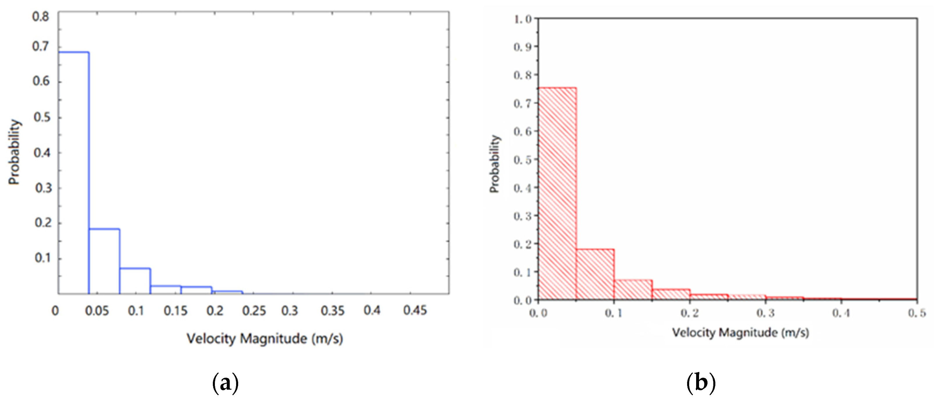
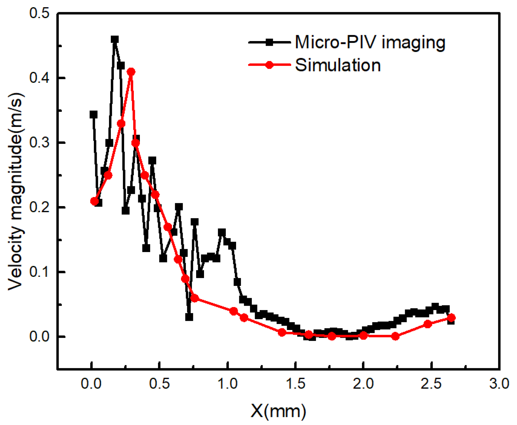
2. Model Verification via Micro-PIV

The statistical results of liquid phase velocity magnitudes of all grid cells in the entire flow channel under operating conditions 3 obtained by simulation calculation and micro-PIV imaging are shown in Figure 1. It can be seen that the statistical results of these two methods were in good accordance. In addition, by capturing a certain liquid column, the velocity curve of the liquid column from the tip to the rear was also analyzed with the simulation and micro-PIV imaging method, as shown in Figure 2. It can be observed that the velocity at the tip was the largest, while the velocity at the interior of the liquid column was relatively lower and uniform in both the simulation and micro-PIV imaging results. Therefore, it can be concluded that the characteristics of the slug flow field obtained by micro-PIV imaging were consistent with the simulation results, indicating that the latter were reliable. The discrepancies in Figure 2 could be attributed to the experimental error caused by many experimental factors, such as the wall roughness caused by the microchannel processing technology, the error of PIV measurement, etc.
Energies 15 01465 g003

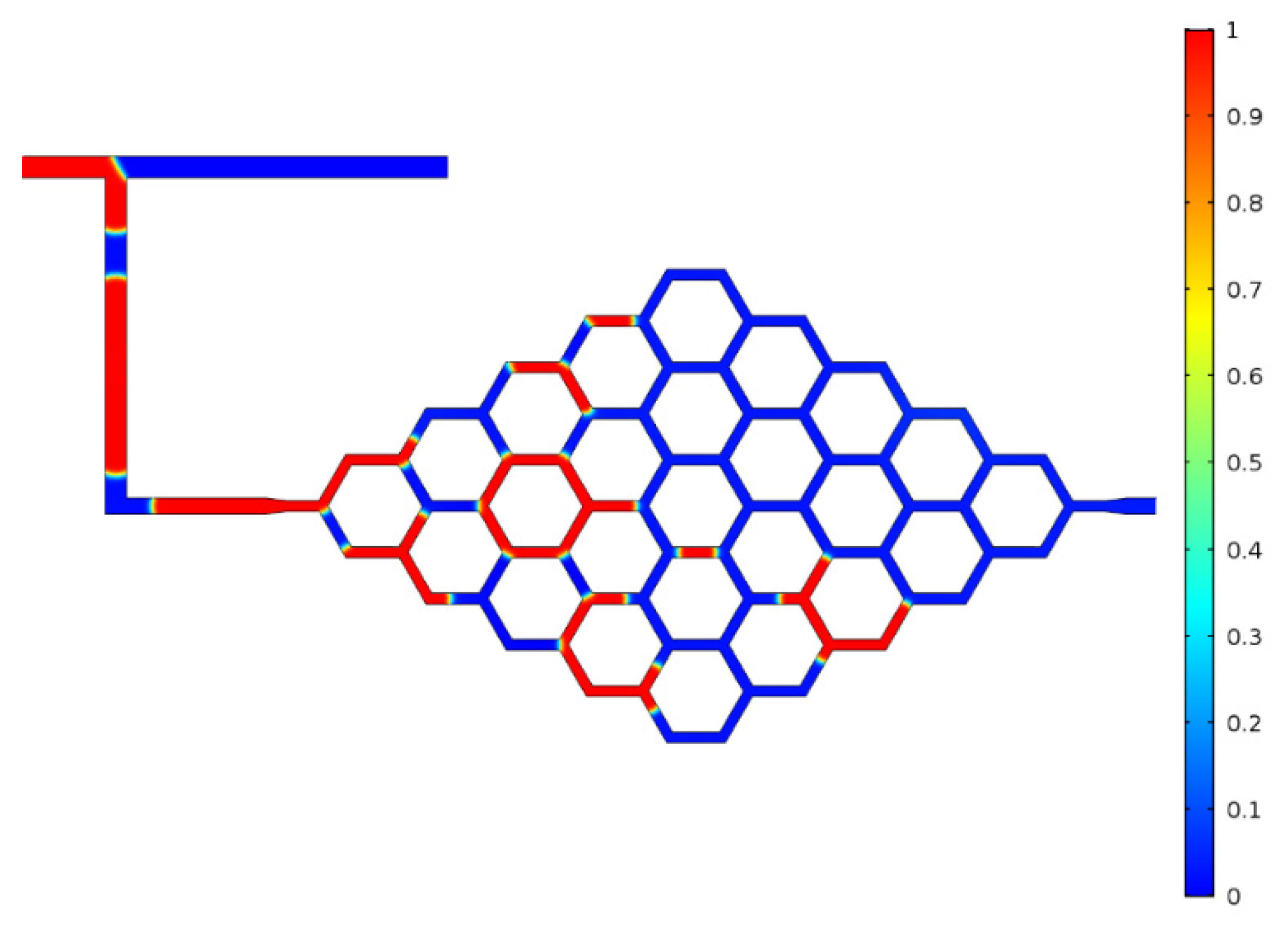
3. Flow Characteristics Analysis

The phase distribution can intuitively reflect the flow characteristics in the microchannel. Figure 3 shows the volume fraction distribution contour under condition 3. Typical slug flow pattern was observed under the investigated conditions. The overall gas volume fraction in the microreactor increased almost linearly as the inlet gas velocity increased (Figure 4). Moreover, it can be seen from Figure 3 that the splitting of the liquid slug at the bifurcation of the honeycomb microchannel was random. Under the driving force from the upstream fluid, the part of liquid slugs broken up at the bifurcation and the rupture were both symmetrical and asymmetrical, leading to the non-uniformity of flow in each branch of the honeycomb microchannel.
Energies 15 01465 g005

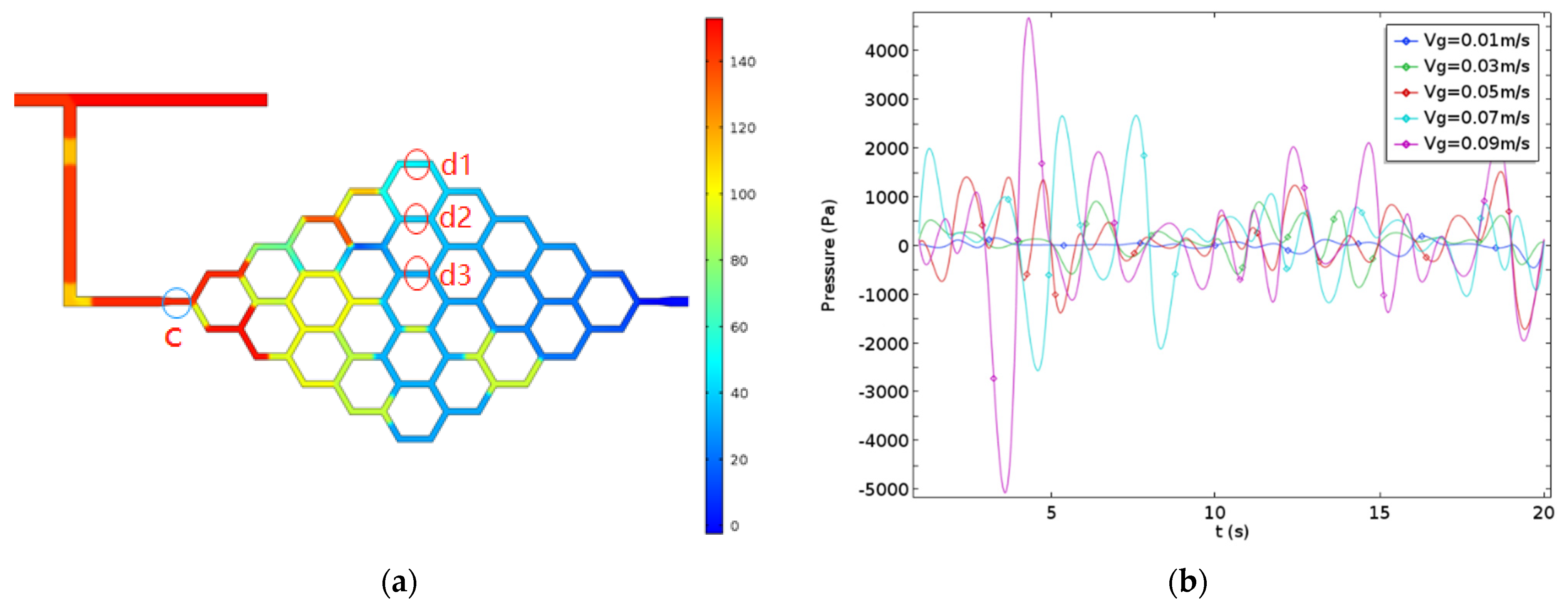
4. Pressure Analysis

The pressure distribution in the honeycomb microchannel under condition 3 can be found in Figure 5a. It was reported that the pressure drop of the gas–liquid flow through the overall arborescence structure increased sharply with the inlet gas flow rate [20]. As for the honeycomb microreactor, the pressure drop increased more slowly, indicating that the design of the microchannel was beneficial for reducing energy consumption. The pressure distribution was closely related to the volume fraction distribution shown in Figure 3. The pressure in the gas phase was higher than that in the liquid phase next to it. Moreover, it can be found that along the direction of gas–liquid flow, the pressures of both the gas and liquid phases decreased, but the pressure drop in the liquid phase seemed more pronounced.
Energies 15 01465 g009

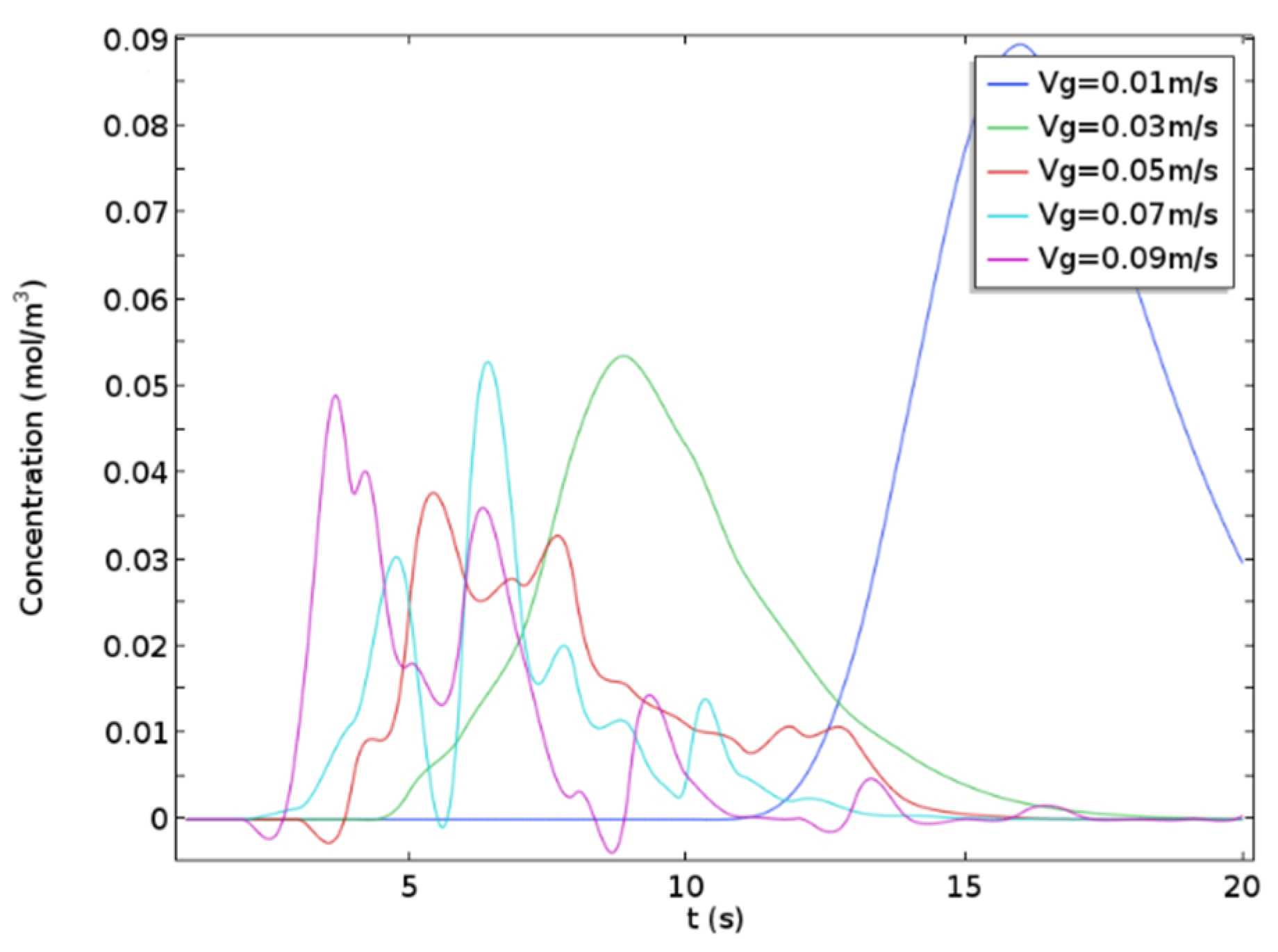
5. Residence Time Distribution

By coupling the model of transport of diluted species, the evaluation of the tracer particles’ concentration in the liquid phase with the time was simulated in the present work with the purpose to analyze the residence time distribution. Figure 6 shows the concentration of the tracer particles at the exit of the honeycomb microreactor as a function of time under different operating conditions. 
Energies 15 01465 g011

6. Conclusions

  • Under current honeycomb configuration, the liquid slug split at the bifurcation randomly, leading to the non-uniformity of the flow in the microreactor. The flow of liquid slug was dominated by the inertial force.
  • The pressure distribution was closely related to the phase distribution. The pressure in the gas phase was higher than that in the nearby liquid phase, and it decreased more slowly along the gas–liquid slug path.
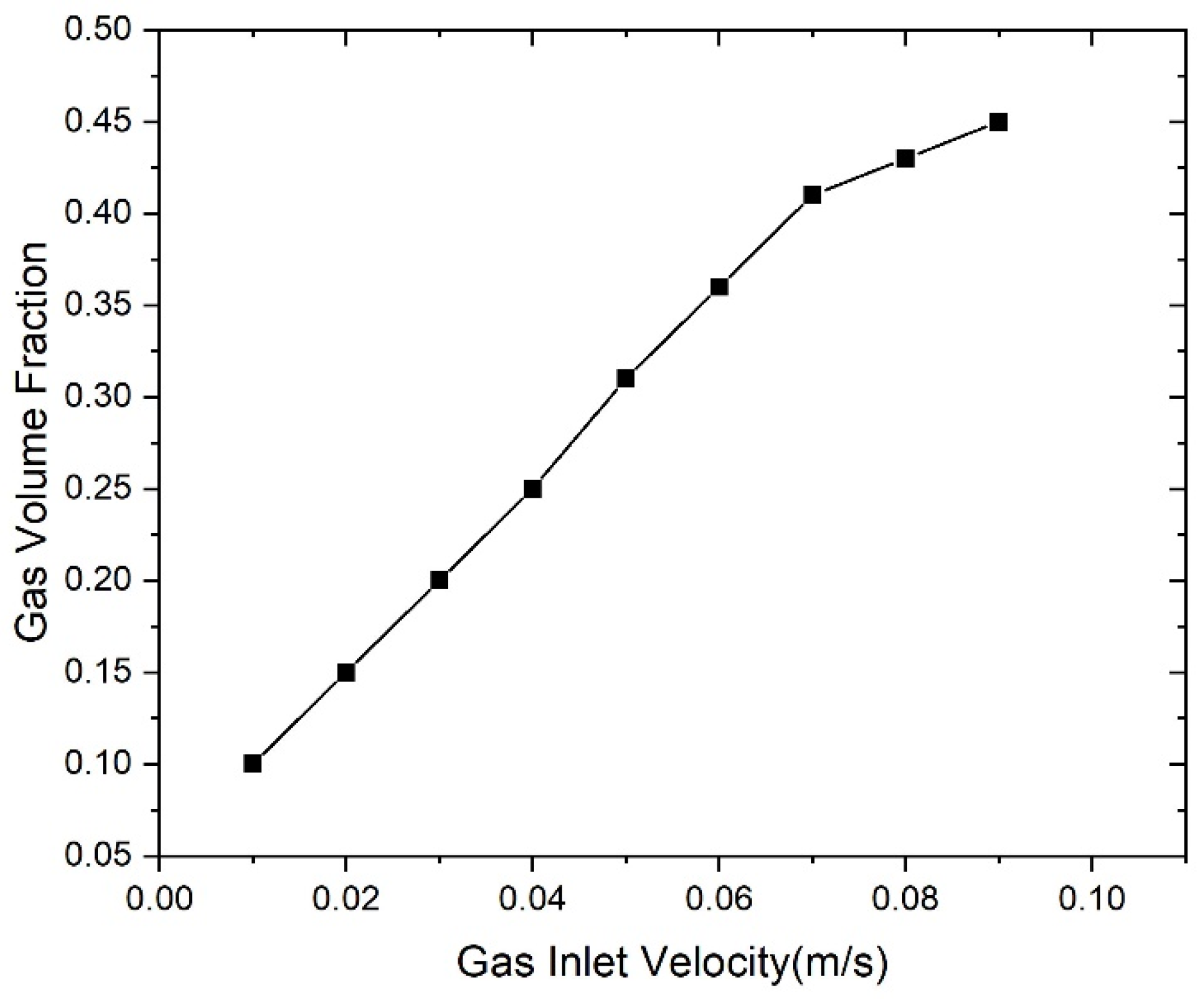
  • The increasing inlet gas velocity promoted the fluctuation of pressure inside the honeycomb microreactor, but the main fluctuation frequency remained unaffected. With the increasing inlet gas velocity, the gas phase volume fraction and the gas slug length increased, while the liquid slug length decreased.
  • Higher inlet gas velocity increased the turbulence in the liquid phase flow field and resulted in the deviation of residence time distribution from normal distribution, leading to a lower variance of the residence time, which was beneficial for practical high throughput applications. In the gas–liquid interface, there was a sudden change of velocity and secondary flow, which was positively correlated with the velocity magnitude, enhancing the micromixing inside the liquid slugs.
  • Vortices and eddy diffusion in the liquid columns are favorable for enhancing the mass transfer inside the liquid.

References

  1. Jähnisch, K.; Hessel, V.; Löwe, H.; Baerns, M. Chemistry in microstructured reactors. Angew. Chem. Int. Ed. 2004, 43, 406–446.
  2. Ramzan, M.; Khan, N.S.; Kumam, P. Mechanical analysis of non-Newtonian nanofluid past a thin needle with dipole effect and entropic characteristics. Sci. Rep. 2021, 11, 19378.
  3. Khan, N.S.; Shah, Q.; Sohail, A.; Kumam, P.; Thounthong, P.; Muhammad, T. Mechanical aspects of Maxwell nanofluid in dynamic system with irreversible analysis. ZAMM J. Appl. Math. Mech. Z. Für Angew. Math. Und Mech. 2021, 101, e202000212.
  4. Turkyilmazoglu, M. Magnetohydrodynamic Liquid Plug Running in a Micro-Channel: Analytical Solutions. J. Biomech. Eng. 2020, 143, 011012.
  5. Li, H. Catalytic Methane Combustion in Microreactors. 2020. Available online: https://tel.archives-ouvertes.fr/tel-03022256/document (accessed on 15 January 2022).
  6. Wiggins, S.; Ottino, J.M. Foundations of chaotic mixing. Philos. Trans. R. Soc. London. Ser. A Math. Phys. Eng. Sci. 2004, 362, 937–970.
  7. Adamson, D.N.; Mustafi, D.; Zhang, J.X.J.; Zheng, B.; Ismagilov, R.F. Production of arrays of chemically distinct nanolitre plugs via repeated splitting in microfluidic devices. Lab Chip 2006, 6, 1178–1186.
  8. Baroud, C.N.; Gallaire, F.; Dangla, R. Dynamics of microfluidic droplets. Lab Chip 2010, 10, 2032–2045.
  9. Bringer, M.R.; Gerdts, C.J.; Song, H.; Tice, J.D.; Ismagilov, R.F. Microfluidic systems for chemical kinetics that rely on chaotic mixing in droplets. Philos. Trans. R. Soc. London. Ser. A Math. Phys. Eng. Sci. 2004, 362, 1087–1104.
  10. Manga, M. Dynamics of drops in branched tubes. J. Fluid Mech. 1996, 315, 105–117.
  11. Vladisavljević, G.T.; Khalid, N.; Neves, M.A.; Kuroiwa, T.; Nakajima, M.; Uemura, K.; Ichikawa, S.; Kobayashi, I. Industrial lab-on-a-chip: Design, applications and scale-up for drug discovery and delivery. Adv. Drug Deliv. Rev. 2013, 65, 1626–1663.
  12. Conchouso, D.; Castro, D.; Khan, S.A.; Foulds, I.G. Three-dimensional parallelization of microfluidic droplet generators for a litre per hour volume production of single emulsions. Lab Chip 2014, 14, 3011–3020.
  13. Lim, J.; Caen, O.; Vrignon, J.; Konrad, M.; Taly, V.; Baret, J.-C. Parallelized ultra-high throughput microfluidic emulsifier for multiplex kinetic assays. Biomicrofluidics 2015, 9, 034101.
  14. Kang, D.K.; Gong, X.; Cho, S.; Kim, J.-Y.; Edel, J.B.; Chang, S.-I.; Choo, J.; Demello, A.J. 3D droplet microfluidic systems for high-throughput biological experimentation. Anal. Chem. 2015, 87, 10770–10778.
  15. Coppens, M.O. A nature-inspired approach to reactor and catalysis engineering. Curr. Opin. Chem. Eng. 2012, 1, 281–289.
  16. Yu, X.; Zhang, C.; Teng, J.; Huang, S.-Y.; Jin, S.-P.; Lian, Y.-F.; Cheng, C.-H.; Xu, T.-T.; Chu, J.-C.; Chang, Y.-J.; et al. A study on the hydraulic and thermal characteristics in fractal tree-like microchannels by numerical and experimental methods. Int. J. Heat Mass Transf. 2012, 55, 7499–7507.
  17. Liu, H.; Zou, M.Q.; Wang, D.L.; Yang, S.-S.; Liang, M.-C. A honeycomb model for tortuosity of flow path in the leaf venation network. Int. J. Mod. Phys. C 2014, 25, 1450015.
  18. Turkyilmazoglu, M. Combustion of a solid fuel material at motion. Energy 2020, 203, 117837.
  19. Turkyilmazoglu, M. Cooling of Particulate Solids and Fluid in a Moving Bed Heat Exchanger. J. Heat Transf. 2019, 141, 114501.1–114501.5.
  20. Hou, J.; Qian, G.; Zhou, X. Gas-liquid mixing in a multi-scale micromixer with arborescence structure. Chem. Eng. J. 2011, 167, 475–482.
More
Information
Contributor MDPI registered users' name will be linked to their SciProfiles pages. To register with us, please refer to https://encyclopedia.pub/register :
View Times: 455
Revisions: 2 times (View History)
Update Date: 07 Mar 2022
1000/1000
ScholarVision Creations