Your browser does not fully support modern features. Please upgrade for a smoother experience.
Submitted Successfully!
 +1 credit
Thank you for your contribution! You can also upload a video entry or images related to this topic.
For video creation, please contact our Academic Video Service.
| Version | Summary | Created by | Modification | Content Size | Created at | Operation |
|---|---|---|---|---|---|---|
| 1 | Fu-Hao Chen | + 2569 word(s) | 2569 | 2022-02-08 07:51:25 | | | |
| 2 | Yvaine Wei | + 3 word(s) | 2572 | 2022-02-18 07:24:32 | | |
Video Upload Options
We provide professional Academic Video Service to translate complex research into visually appealing presentations. Would you like to try it?
Cite
If you have any further questions, please contact Encyclopedia Editorial Office.
Chen, F. Autostereoscopic Displays Based on Various Display Technologies. Encyclopedia. Available online: https://encyclopedia.pub/entry/19575 (accessed on 24 July 2026).
Chen F. Autostereoscopic Displays Based on Various Display Technologies. Encyclopedia. Available at: https://encyclopedia.pub/entry/19575. Accessed July 24, 2026.
Chen, Fu-Hao. "Autostereoscopic Displays Based on Various Display Technologies" Encyclopedia, https://encyclopedia.pub/entry/19575 (accessed July 24, 2026).
Chen, F. (2022, February 17). Autostereoscopic Displays Based on Various Display Technologies. In Encyclopedia. https://encyclopedia.pub/entry/19575
Chen, Fu-Hao. "Autostereoscopic Displays Based on Various Display Technologies." Encyclopedia. Web. 17 February, 2022.
Copy Citation
The autostereoscopic display is a promising way towards three-dimensional-display technology since it allows humans to perceive stereoscopic images with naked eyes. However, it faces great challenges from low resolution, narrow viewing angle, ghost images, eye strain, and fatigue. Nowadays, the prevalent liquid crystal display (LCD), the organic light-emitting diode (OLED), and the emerging micro light-emitting diode (Micro-LED) offer more powerful tools to tackle these challenges.
autostereoscopic display
Micro-LED
light-emitting diode
1. Introduction
Accommodation refers to the adjustment of focal length of eyes on the watched object; convergence refers to the rotation of eyeballs to converge on the perceived point; binocular parallax, or binocular disparity, refers to the slightly different perceived images from left and right eyes, and the brain merges the two images into a stereoscopic image. It is the most important depth cue utilized in 3D displays. The last, motion parallax, refers to the relative location change of objects when moving the viewing position.
In these cues, binocular parallax gives rise to a strong depth sensation. Based on binocular parallax, many types of 3D displays were invented. In general, they can be classified into stereoscopic and autostereoscopic displays, respectively. Stereoscopic displays require audience wearing specialized glasses to perceive 3D images, but autostereoscopic displays permit watching 3D images with naked eyes.
Autostereoscopic displays of interest to the market, and there are several commercial products which employ them, such as Nintendo 3DS, HTC EVO 3D, Sony Spatial Reality Display, and Google Starline. It shows that many corporations are striving to promote autostereoscopic displays to consumers. However, they still face challenges such as image blur, low resolution, narrow viewing angular range, limited viewing distance, eye strain, and fatigue [1][2].
2. Light-Field Displays
For autostereoscopic displays, the “light field” is a pivotal concept that must be mentioned. The term “light field” was coined by Andrey Gershun [3] in 1936. It illustrates the light intensity at a given position (x, y, z) and direction ( , ), and it is a 5D plenoptic function [4]. Furthermore, in 1996, Marc Levoy and Pat Hanrahan [5] proposed that the 5D function can be reduced to a 4D function as L(x, y, , ) since the light ray remains unchanged along its propagation in free space. It implies that it is able to use a display that emits 2D spatial and 2D directional light rays to reproduce the light field including the depth information as shown in Figure 1a. Therefore, it fundamentally guarantees that 3D displays are feasible in principle, rather than a science fiction. However, the 4D function still carries too much information than the present technology can handle; to further reduce the information quantity, the vertical parallax depending on is dropped, since human perceives depth mainly based on horizontal binocular parallax of . Thus, the 4D function is reduced to a 3D function of (x, y, ) as shown in Figure 1b.
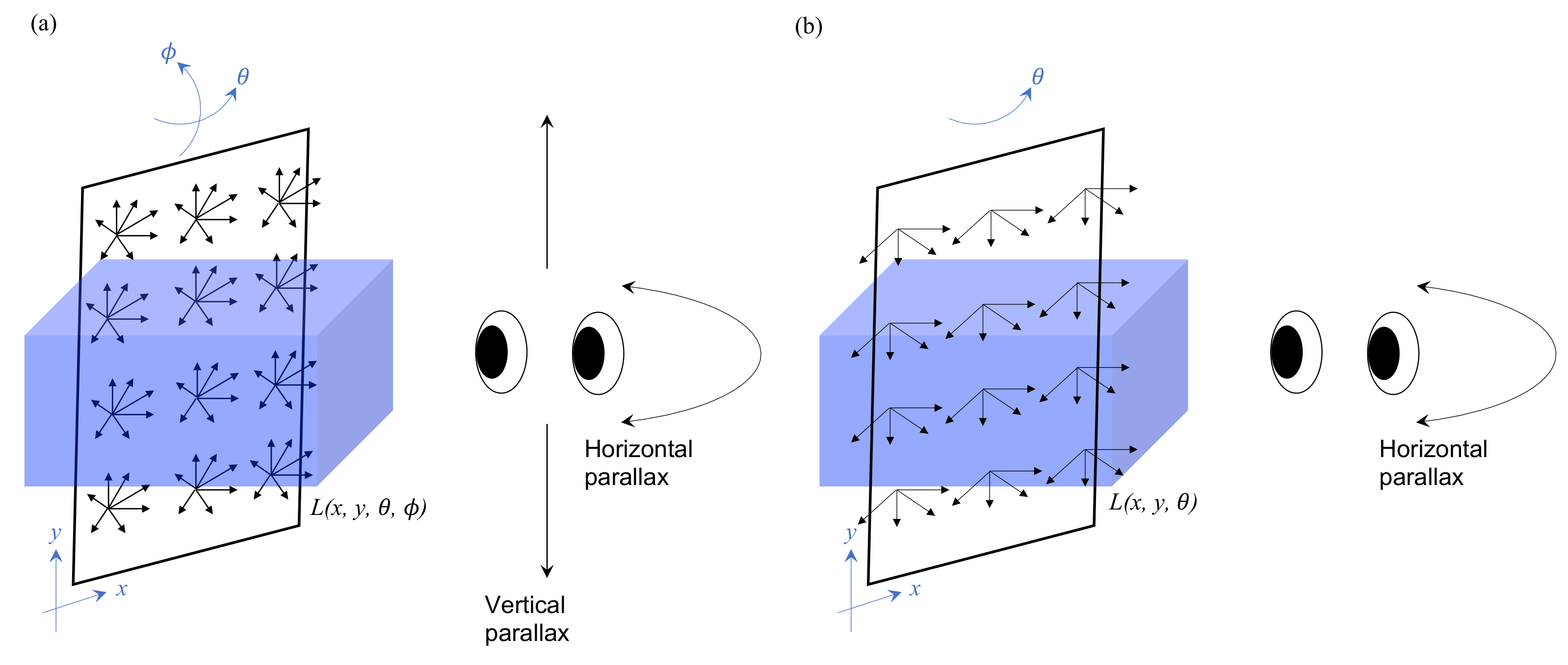
Figure 1. (a) A 4D light-field function L(x, y, , ) fully presents the information of a 3D scene with a horizontal and vertical parallax. (b) To reduce the huge amount of information of a 4D light field, the ϕ-direction information is dropped and simplified into a 3D function L(x, y, ), and only the binocular and horizontal parallax is preserved.
3. Spatial Multiplex
Since the binocular parallax gives rise to a strong depth cue, people start to think how to make two eyes catch different perspective images. A parallax barrier or a lenticular sheet can achieve this. These methods usually redistribute the pixels evenly into two eyes, and this is called spatial multiplex. It is compatible with the modern liquid crystal display (LCD) or organic light emitting diode (OLED) display, but the drawback is that it reduces the resolution and luminance of the display.
3.1. Parallax Barrier
In 1896, Auguste Berthier [6] proposed a “parallax barrier” to create an auto-stereogram. Its mechanism is described in Figure 2, showing that the parallax barrier is (a) in front of the display panel or (b) behind the display panel. The parallax barrier is an interlace of transparent and opaque stripes. For the left eye, only the pixels labeled as L are perceived, and the pixels labeled as R are blocked. In the same way, only pixels labeled as R are perceived by the right eye. Thus, the left and right eyes watch different images, and it generates binocular parallax. In Figure 2b, the parallax barrier is inserted between the display panel and the backlight to make the barrier invisible, so people would not be aware of the existence of black strips.
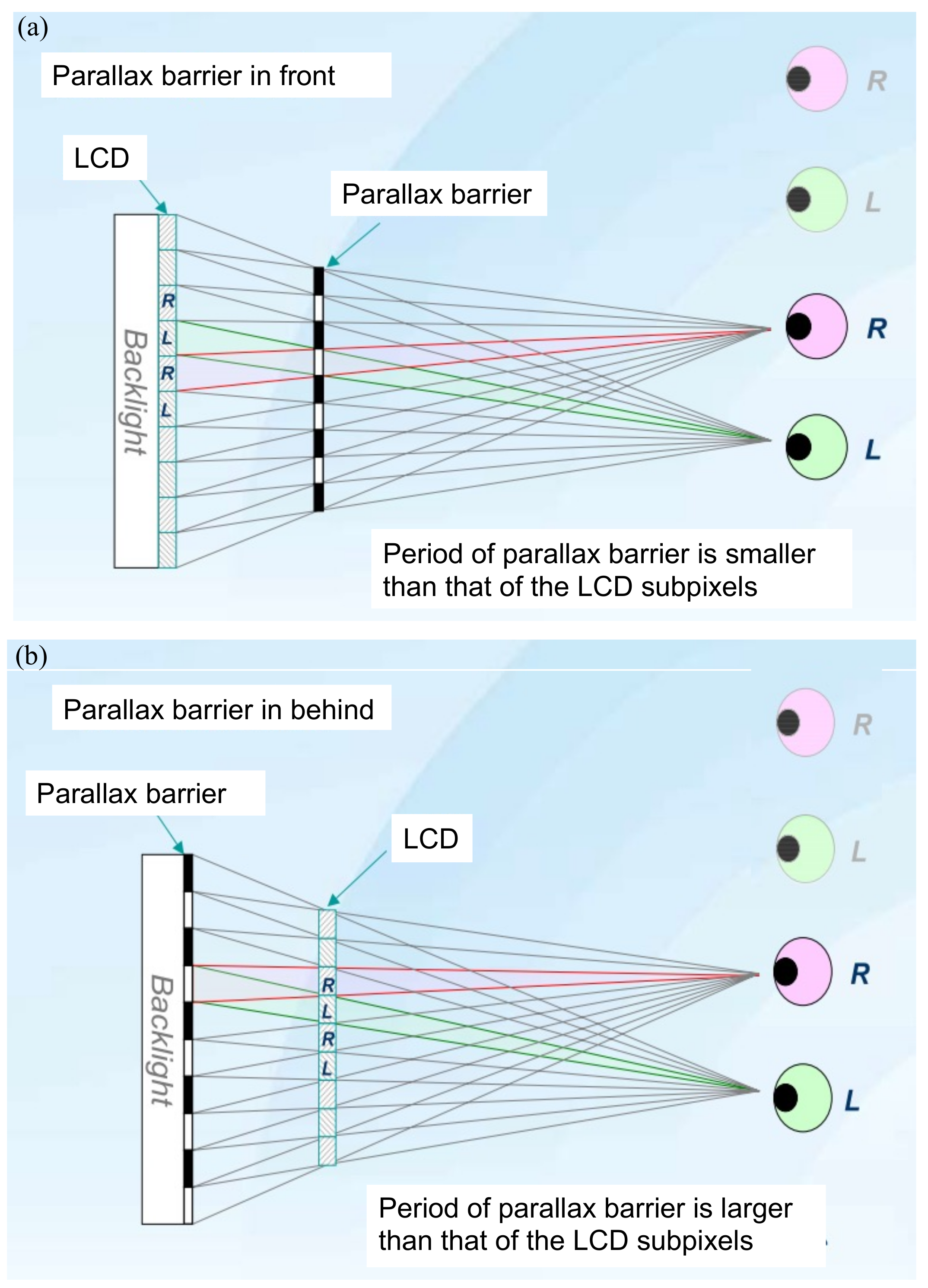
Figure 2. The parallax barrier is located (a) in front of the LCD panel or (b) behind the LCD panel. The parallax barrier generates the binocular parallax.
The method can be modified into multiple views by changing the pitch of the barrier. Figure 3 demonstrates a four-view design, the pitch of the parallax barrier is slightly smaller than four times of the subpixel pitch to converge the light into a single view, and the width of the transparent region determines the brightness. Wider transparent region increases the brightness, but induces more crosstalk.
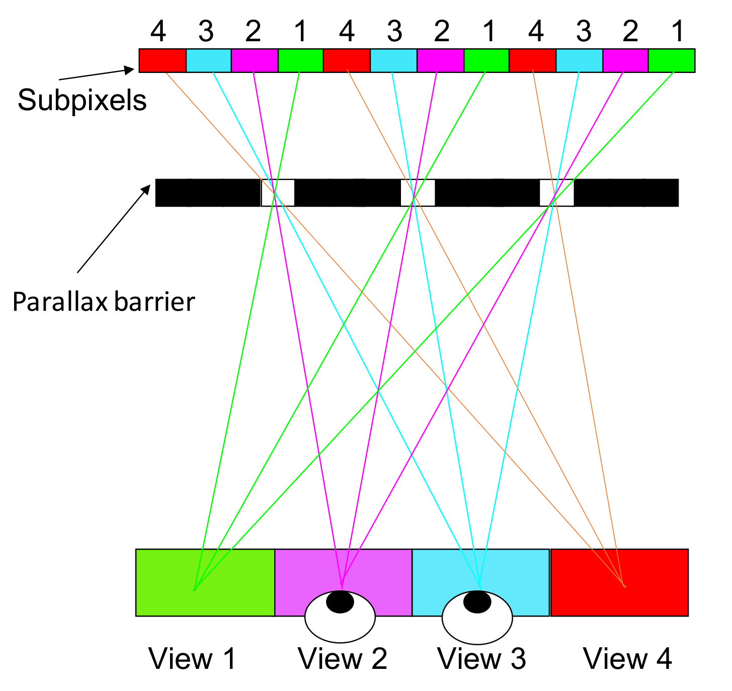
Figure 3. In the four-view design, the pitch of the parallax barrier is slightly smaller than four times the subpixel pitch.
3.2. Lenticular Lenses
The parallax-barrier method faces the degradation of brightness. To overcome the problem, Hess [7] invented a lenticular-lens method in 1915, which is described in Figure 4. The lenticular sheet is a one-dimensional cylindrical micro-lens array which replaces the role of the parallax barrier and collimates the diffused light from pixels into a specific direction, being received by a specific eye in the end. Hence, two eyes receive different images and merge them into an image with depth.
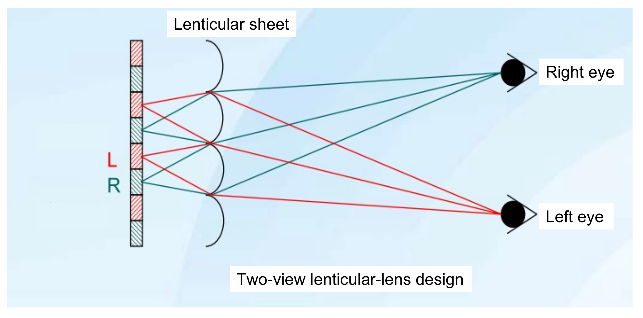
Figure 4. The lenticular-lens method used to produce a 3D image (top view) is plotted. It is similar to the parallax barrier; however, a lenticular sheet guides left-eye pixels to the left eye, and right-eye pixels to the right eye without blocking light.
4. Time Multiplex
The main shortcoming of the spatial multiplex is the severe drop in resolution, especially for multiview displays. To overcome the problem, “time multiplex” was proposed to solve it. The idea is multiplying the refresh rate by the number of views and reusing each pixel multiple times to compensate for the loss of resolution. This method projects each view time-sequentially. As an example of a two-view display, the refresh rate needs to be 60 Hz × 2 = 120 Hz to ensure that both eyes perceive images without flickers. Nonetheless, achieving an even higher refresh rate is not easy for common LCDs and the directional device, and it is also one of the major barriers to pursuing multiviews in time multiplex.
In general, the spatial multiplex can be generalized to time multiplex. For a parallax barrier, we can just shift the position of open slits by one half pitch, so all the pixels are perceived by two eyes, illustrated in Figure 5. In this case, the barrier and frame rate are scanning with doubled 120 Hz, so human eyes would not feel flickers.
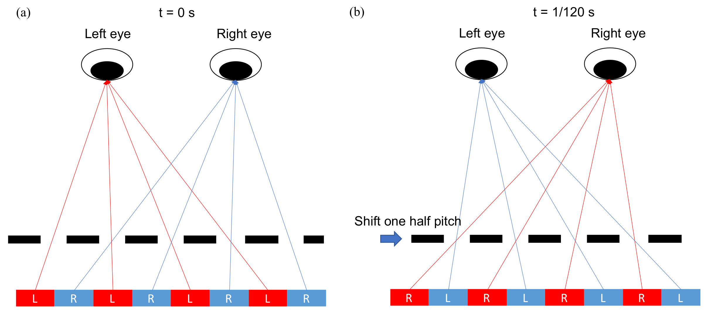
Figure 5. The parallax barrier slits are shifted by one half pitch within 1/120 s, so both eyes can perceive red and blue pixels, and then the resolution is retained. (a) As t = 0 s, the parallax barrier is at the original place. (b) As t = 1/120 s, the parallax barrier shifts one half pitch.
5. Integral Imaging
Integral imaging (InIm) was invented by the Nobel laureate in physics, Gabriel Lippmann in 1908, and he coined this technique as “integral photography” [8]. Figure 6 shows the idea behind InIm: A voxel [9] is formed by intersecting rays being emitted from the 2D display and being directed to the position of voxel by the 2D micro-lens array. In other words, the multiple perspectives of a voxel are recorded by the 2D micro-lens array and reconstructed by the reversed way, and it presents a full parallax. If the ray density is high enough to allow at least two rays into a single eye, then it shows the accommodation effect [10] that resolves the accommodation-convergence conflict [4]. Hence, it mitigates the fatigue problem. The range of pupil diameter is 4–6 mm [11], indicating the ray separation is 2–3 mm when arriving at the eyes, so hundreds of rays in horizontal and vertical directions are required to cover a head movement in hundreds of millimeters, and the overall ray number could be tens of thousands; thus, the native display resolution must be tens of thousands-fold the perceived resolution, so an extremely-high-resolution display is required.
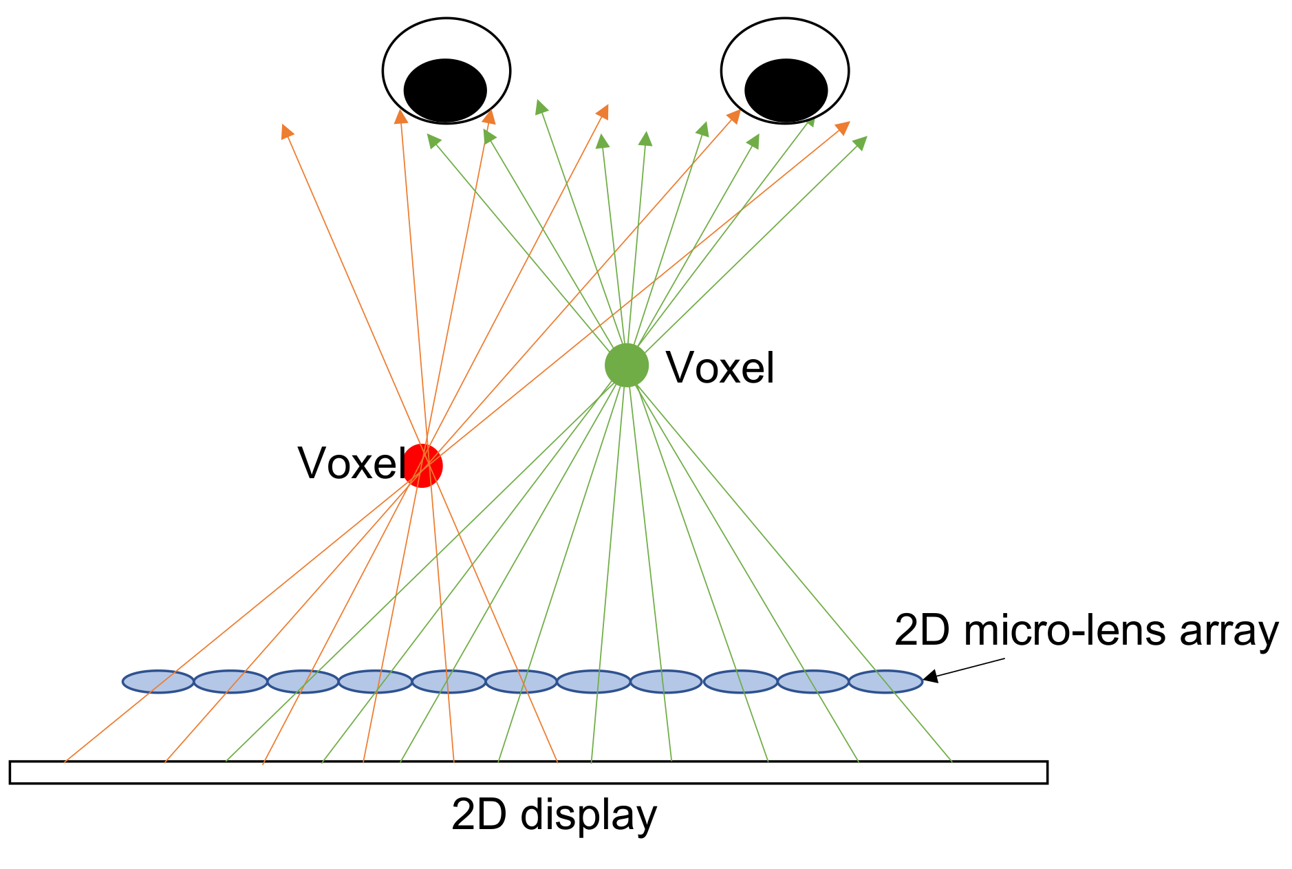
Figure 6. The principle behind integral imaging: The light field is reconstructed by the rays from the 2D display, which are directed to the voxel’s position by the micro-lens 2D array and intersect with a voxel.
6. Electronic Holography
Holography was invented by the Nobel laureate, Dennis Gabor [12] in 1947. It records all the information of the light field, consisting of its amplitude and phase. In a reversed manner, the light field is reconstructed as a 3D image. Since holography does not mimic 3D with 2D images, it builds the authentic 3D wavefront instead; hence, holography is regarded as the ultimate 3D display. The formation of holography, in Figure 7, is that the object beam interferes with the reference beam coherently and the interference fringe is recorded on a photo film.
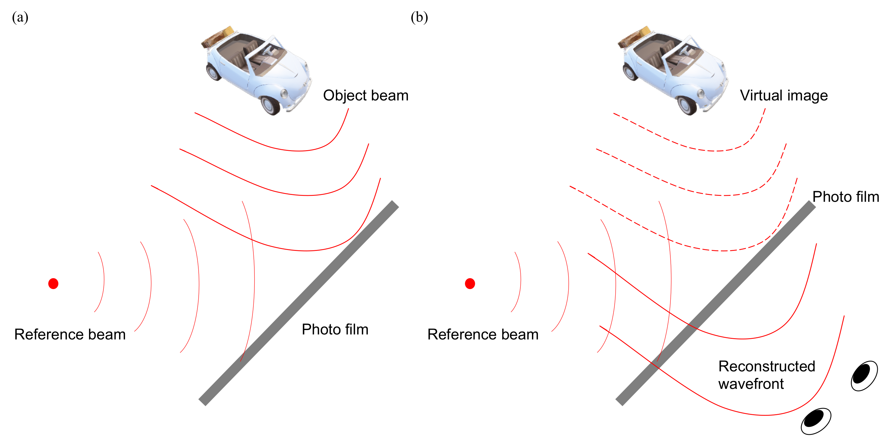
Figure 7. (a) The wavefront of the object beam interferes with the reference beam, and the fringe is recorded on a photo film to form a hologram. (b) Illuminating a hologram with the original reference beam reconstructs the wavefront of the object beam, so it includes the phase and amplitude such that eyes sense the depth of the object.
7. Comprehensive Analysis of 3D Display Based on LCD, OLED, and Micro-LED
Nowadays, LCD and OLED dominate the display market, and the micro-light emitting diode (Micro-LED) is the next emerging display technology. All of them can be used to implement 3D displays based on different scenarios. LCD requires a backlight to light the display on, so it has an extra flexibility to implement the light-directional-control elements within the backlight, such as the parallax barrier in Figure 1b, directional backlight [13][14], or a light-bar method.
As shown in Figure 8, LCD usually has an encapsulation glass around 0.5 mm thick, which leads to small viewing zone pitch comparing to the larger viewing zone pitch of OLED/Micro-LED whose encapsulation layer is less than 1 µm [15]. Under the same number of views, small viewing zone pitch shrinks the viewing angle, which is harmful to auditing experience. Hence, OLED/Micro-LED have the advantage of enlarging the viewing angle than LCD with the same number of views.
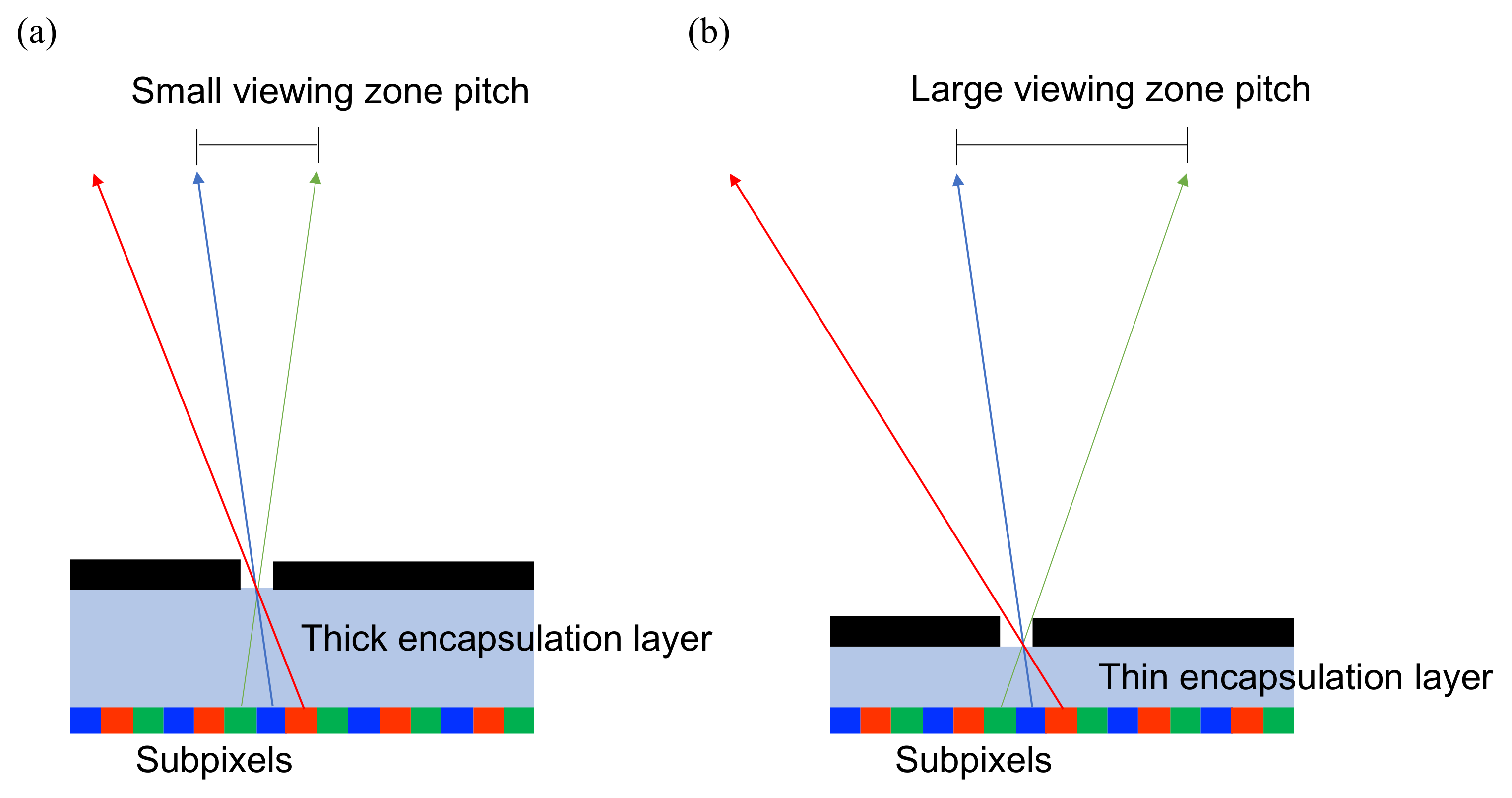
Figure 8. (a) The viewing zone pitch is small in a thick-encapsulation-layer system, such as LCD, that has a thick front glass around 0.5 mm. (b) The thin-encapsulation-layer system, e.g., OLED/Micro-LED has an ultra-thin film less than 1 µm, which shows a large viewing zone pitch.
On the other hand, OLED usually has a pentile-pixel arrangement (Figure 9), which is more sophisticated than LCD’s RGB arrangement, and it requires a special pattern design for the parallax barrier. Lee and Kim have shown how to design the parallax barriers in their work [16][17].
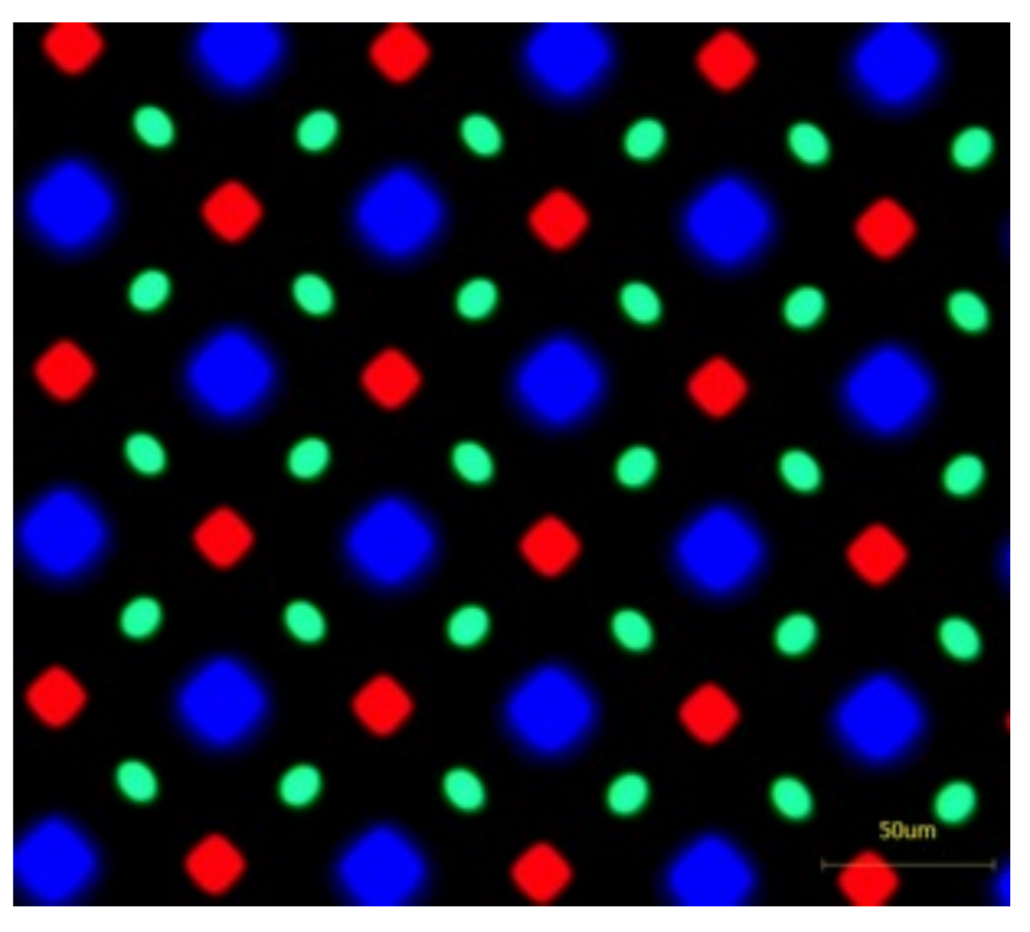
Figure 9. The pentile-pixel-arrangement image captured from an OLED display, showing a more sophisticated pattern than the RGB pattern of LCD, such that it is trickier to design the parallax barrier or lenticular pattern.
8. The Future of 3D Display: Micro-LED Plays the Key Role
Micro-LED is an emerging technology that potentially drives the realization of 3D displays. Micro-LED provides the pixel size down to few microns, equivalent to tens of thousands of ppi [18]. Micro-LED satisfies the ultra-high-resolution requirement for InIm, and it is able to push the development of InIm greatly forward. Second, Micro-LED provides response time of nanoseconds such that it can be used as a time-multiplex display. Third, Micro-LED offers a partial-coherent light source because of its small-area luminance, and it is capable of replacing the laser as the point light source to reduce the speckle effect for the electronic holographic display [19].
On the other hand, considering Micro-LED as a function of the backlight, the configuration in Figure 10 illustrates how the rays propagate through each pixel and converge to the viewing zone; here is an example for a four-view display, and the pitch of line stripes is slightly larger than four times the pixels. In this manner, the narrower the light stripe is, the less crosstalk is induced. Taking the advantage of small dimension of Micro-LED, the crosstalk can be effectively suppressed. ITRI [20][21] has developed a light-stripe backlight with inverted trapezoids, but its light efficiency is moderate. Now, it is possible to assemble Micro-LEDs as the light-stripe backlight and promote their light efficiency significantly.
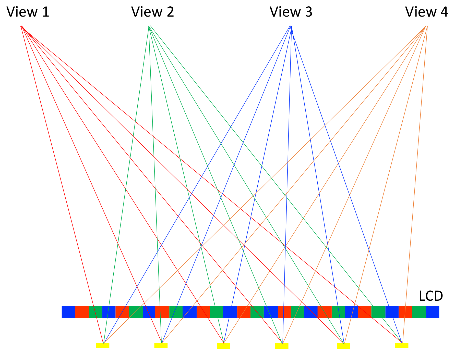
Figure 10. The Micro-LEDs form a light-stripe 1D array with a well-designed pitch, such that the partial pixels are projected to the corresponding views.
This light-stripe method can be generalized to time-multiplex display with multiple sets of light-stripe arrays. In Figure 11, four light-stripe sets are introduced, and they are manipulated with the lighting on and off in the order of yellow, purple, grey, and black cyclically. Each light-stripe set projects a quarter of the pixels to a single eye, and four sets of light stripes allow all the pixels to be perceived by a single eye. Hence, it achieves a full resolution with time-multiplex lighting on-and-off. For the four-view example, it turns 240 Hz lighting on and off. Based on the fast response of Micro-LED, it is easy to turn high-frequency lighting on and off. ITRI [13][22] has demonstrated another variant with light stripes and a lenticular sheet to collimate the backlight into a single direction; turning on different light-stripe sets directs the collimated backlight into different directions, and full-resolution images are delivered into various directions. In addition, Micro-LED can be transferred onto a transparent glass substrate, and it becomes a transparent display that owns a floating 3D effect [23]. Japan virtual idol Hatsune Miku already demonstrated a projection image onto a transparent curved screen to mimic a holographic image [24]. Furthermore, Micro-LED has much higher luminance, up to tens of thousands of nits, than LCD, OLED, so it can be used outdoors where the ambient light is high. Lastly, Micro-LED has a fast response time down to nano-seconends [25], it is especially suitable for time-multiplex 3D displays. Speeding up the frame rate up to 960 Hz and with the same-speed scanning barrier or a deflector such as the LC deflector shown in Figure 8, it generates a sixteen-fold multiview without any loss of resolution. Moreover, Micro-LED is more power-saving such that it prolongs the battery time for mobile devices, such as smart phones and tablets.
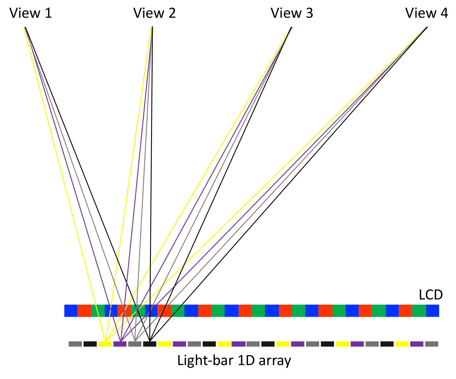
Figure 11. Introducing multiple sets of light-stripe arrays (grouped by colors) and switching each set of light stripes on and off sequentially allows every pixel to be perceived at each view. It is a time-multiplex method to achieve full resolution. Here, only the rays emitted from a single light-stripe set are plotted, and each view receives four pixels rather than a single pixel to demonstrate that a full-resolution image is perceived.
9. Conclusions
The understanding of how human eyes physiologically perceive three-dimensional objects, and the optical principles behind autostereoscopic displays, were comprehensively reviewed, including the concept of the light field, parallax barrier, lenticular lens, integral imaging, and electronic holography. On top of that, based on LCD, OLED, and Micro-LED, their pros and cons were investigated for the implementation of autostereoscopic displays. Among these technologies, Micro-LED has the advantages of high resolution, fast response time, ultra-thin encapsulation layer, and high brightness, and they are beneficial to improving the performance of autosteroscopic displays. Based on these features, several implementations of autostereoscpic displays with Micro-LED were proposed: a Micro-LED light-stripe backlight with a LCD, a high-resolution Micro-LED display with a microlens array or a high-speed scanning barrier/deflector, and a transparent floating display
References
- Ukai, K.; Howarth, P.A. Visual fatigue caused by viewing stereoscopic motion images: Background, theories, and observations. Displays 2008, 29, 106–116.
- Kim, C.Y. New challenges for future 3D TV. In Proceedings of the WIO 2013—12th Workshop on Information Optics, Tenerife, Spain, 15–19 July 2013; pp. 1–3.
- Gershun, A. The Light Field. J. Math. Phys. 1939, 18, 51–151.
- Martínez-Corral, M.; Javidi, B. Fundamentals of 3D imaging and displays: A tutorial on integral imaging, light-field, and plenoptic systems. Adv. Opt. Photonics 2018, 10, 512.
- Levoy, M.; Hanrahan, P. Light field rendering. In Proceedings of the 23rd Annual Conference on Computer Graphics and Interactive Techniques (SIGGRAPH 1996), New York, NY, USA, 8 January 1996; pp. 31–42.
- Berthier, A. Images stéréoscopiques de grand format. Cosmos Revue Encyclopédique Hebdomadaire des Progrès des Sciences 1896, 34, 210–227.
- Hess, W. Stereoscopic Picture. 1915. Available online: https://en.wikipedia.org/wiki/Autostereoscopy (accessed on 16 December 2021).
- Lippmann, G. Épreuves réversibles. Photographies intégrales. Comptes Rendus de l’Académie des Sciences 1908, 146, 446–451.
- Geng, J. Three-dimensional display technologies. Adv. Opt. Photonics 2013, 5, 456.
- Deng, H.; Wang, Q.H.; Luo, C.G.; Liu, C.L.; Li, C. Accommodation and convergence in integral imaging 3D display. J. Soc. Inf. Disp. 2014, 22, 158–162.
- MacLachlan, C.; Howland, H.C. Normal values and standard deviations for pupil diameter and interpupillary distance in subjects aged 1 month to 19 years. Ophthalmic Physiol. Opt. 2002, 22, 175–182.
- Gabor, D. A new microscopic principle. Nature 1948, 161, 777–778.
- Liou, J.C.; Chen, F.H. Design and fabrication of optical system for time-multiplex autostereoscopic display. Opt. Express 2011, 19, 11007.
- Fattal, D.; Peng, Z.; Tran, T.; Vo, S.; Fiorentino, M.; Brug, J.; Beausoleil, R.G. A multi-directional backlight for a wide-angle, glasses-free three-dimensional display. Nature 2013, 495, 348–351.
- Park, J.S.; Chae, H.; Chung, H.K.; Lee, S.I. Thin film encapsulation for flexible AM-OLED: A review. Semicond. Sci. Technol. 2011, 26, 34001.
- Lee, W.; Shin, Y.; Yoon, J.; Kim, J.; Lee, C.K.; Jeong, Y.; Jang, C.; Hong, J.Y.; Lee, B. Mobile autostereoscopic 3D display using a diamond pixel structured OLED pentile display panel. In Optics InfoBase Conference Papers; OSA Technical Digest (online); Optical Society of America: Seattle, WA, USA, 2014; p. JTu4A.8.
- Kim, J.; Lee, C.K.; Jeong, Y.; Jang, C.; Hong, J.Y.; Lee, W.; Shin, Y.C.; Yoon, J.H.; Lee, B. Crosstalk-reduced dual-mode mobile 3D display. IEEE/OSA J. Disp. Technol. 2015, 11, 97–103.
- Liu, Z.; Lin, C.H.; Hyun, B.R.; Sher, C.W.; Lv, Z.; Luo, B.; Jiang, F.; Wu, T.; Ho, C.H.; Kuo, H.C.; et al. Micro-light-emitting diodes with quantum dots in display technology. Light. Sci. Appl. 2020, 9, 83.
- Deng, Y.; Chu, D. Coherence properties of different light sources and their effect on the image sharpness and speckle of holographic displays. Sci. Rep. 2017, 7, 5893.
- Yen, W.T.; Chen, F.H.; Chen, W.L.; Liou, J.C.; Tsai, C.H. Enhance light efficiency for slim light-strip array backlight on autostereoscopic display. In Proceedings of the 3DTV-Conference: The True Vision-Capture, Transmission and Display of 3D Video (3DTV-CON), Zurich, Switzerland, 15–17 October 2012; pp. 1–4.
- Chen, F.H.; Chen, W.L.; Yen, W.T.; Liou, J.C.; Tsai, C.H. Stereoscopic Display Device. CN103728769B. 2013.
- Chen, F.H.; Tsai, C.H.; Tiao, K.T.; Liou, J.C. Stereoscopic Display. U.S. Patent App. 13/077,987, 2 February 2012.
- Peng, D.; Zhang, K.; Chao, V.S.D.; Mo, W.; Lau, K.M.; Liu, Z. Full-color pixelated-addressable light emitting diode on transparent substrate (LEDoTS) micro-displays by CoB. J. Disp. Technol. 2016, 12, 742–746.
- Liang, N. The application of the holographic laser projection in the entertaining performance. In Proceedings of the IEEE International Conference on Advanced Materials for Science and Engineering: Innovation, Science and Engineering (IEEE-ICAMSE 2016), Tainan, Taiwan, 12–13 November 2016; pp. 629–631.
- Huang, Y.; Hsiang, E.L.; Deng, M.Y.; Wu, S.T. Mini-LED, Micro-LED and OLED displays: Present status and future perspectives. Light. Sci. Appl. 2020, 9, 105.
More
Information
Subjects:
Imaging Science & Photographic Technology; Optics
Contributor
MDPI registered users' name will be linked to their SciProfiles pages. To register with us, please refer to https://encyclopedia.pub/register
:
View Times:
4.2K
Revisions:
2 times
(View History)
Update Date:
21 Feb 2022
Table of Contents


Notice
You are not a member of the advisory board for this topic. If you want to update advisory board member profile, please contact office@encyclopedia.pub.
OK
Confirm
Only members of the Encyclopedia advisory board for this topic are allowed to note entries. Would you like to become an advisory board member of the Encyclopedia?
Yes
No
${ textCharacter }/${ maxCharacter }
Submit
Cancel
Back
Comments
${ item }
|
${ item.createdUser.fullName }
${ item.createdAt }
${ item.vote }
${ item.reply }
Delete
${ reply.createdUser.fullName }
${ reply.createdAt }
${ reply.vote }
Delete
There is no reply to this comment~
${ item.replyTextCharacter }/${ item.replyMaxCharacter }
Submit
Cancel
More
No more~
There is no comment~
${ textCharacter }/${ maxCharacter }
Submit
Cancel
${ selectedItem.replyTextCharacter }/${ selectedItem.replyMaxCharacter }
Submit
Cancel
Confirm
Are you sure to Delete?
Yes
No