 +1 credit
| Version | Summary | Created by | Modification | Content Size | Created at | Operation |
|---|---|---|---|---|---|---|
| 1 | Jiahuan Lin | + 1601 word(s) | 1601 | 2022-01-20 05:05:16 | | | |
| 2 | Yvaine Wei | + 3 word(s) | 1604 | 2022-02-08 03:02:47 | | |
Video Upload Options
The Froude-scaled offshore floating wind turbine model is inevitably affected by the Reynolds number effect, making the model unable to correctly reproduce the thrust performance of the reference wind turbine (RWT). To solve this problem, an Xfoil-AirfoilPrep-Matlab (XAM) system and a wide tip speed ratio search method (WTSM) are proposed to design a wide tip speed ratio (TSR) thrust-match model blade. The XAM system is utilized to select the best airfoil for WTSM by calculating the lift and drag coefficients of several airfoils. The WTSM is utilized to optimize the blade chord and twist. It formalizes the blade chord and twist by polynomials and then optimizes the polynomial coefficients. The thrust coefficients construct the optimization object at different TSRs. For validating the effect of the redesigned blade, the thrust performance is compared to that of the RWT blade. In addition, the thrust performance of redesigned blade at different pitch angles is also calculated and compared to those of the RWT blade. Results show that the thrust performance of redesigned blade matches well with that of the RWT blade at 0 pitch angle, and it can also match the variations of that of the RWT blade at the other pitch angles well.
1. Introduction
2. Scaling Laws and RNE
2.1. Scaling Laws
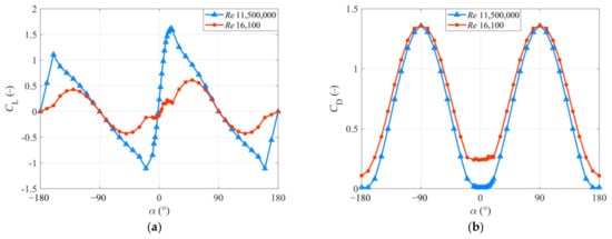
2.2. RNE
3. Airfoil Selection
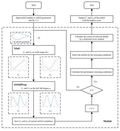
3.1. Xfoil-AirfoilPrep-Matlab (XAM) System
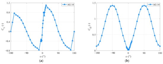
3.2. Result and Discussion of Airfoil Performance
4. Redesigning Blade Solution
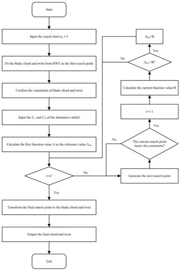
4.1. Wide Tip Speed Ratio Search Method (WTSM)
4.2. Results
4.3. Aerodynamic Analysis with Different Pitch Angle
5. Conclusions
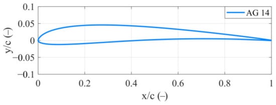
- A XAM system is constructed to guide the airfoil selection. Based on the XAM system, 767 airfoils are compared with each other according to the preliminary screening conditions and the dedicated score method. Finally, the AG 14 airfoil is selected out as the best airfoil.
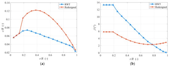
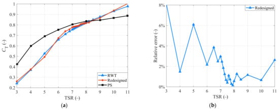
- A WTSM is proposed for a wide TSR thrust-match blade. Based on the WTSM, the blade chord and twist of the redesigned blade with AG 14 airfoil is optimized for a better thrust performance. The CT-TSR curve of the redesigned blade is compared with the RWT blade. Moreover, most of the relative errors are less than 5%, except for the working conditions that TSR = 3 (8%) and TSR = 5 (6%). It proves the thrust performance of the redesigned blade matches that of the RWT blade well at a 0 pitch angle.
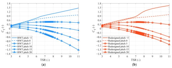
- The thrust coefficients of the proposed redesigned blade in other pitch angles are calculated and compared to those of the RWT blade. Results show that the variations are consistent with the RWT blade. It means that the redesigned blade has great potential in the studies related to control strategy.
References
- Global Wind Energy Council. GWEC Global Wind Report; Global Wind Energy Council (GWEC): Brussels, Belgium, 2021.
- Ju, S.; Huang, Y.; Huang, Y. Study of optimal large-scale offshore wind turbines. Renew. Energy 2020, 154, 161–174.
- Finnegan, W.; Jiang, Y.; Dumergue, N.; Davies, P.; Goggins, J. Investigation and Validation of Numerical Models for Composite Wind Turbine Blades. J. Mar. Sci. Eng. 2021, 9, 525.
- Medina, C.; Álamo, G.M.; Quevedo-Reina, R. Evolution of the Seismic Response of Monopile-Supported Offshore Wind Turbines of Increasing Size from 5 to 15 MW including Dynamic Soil-Structure Interaction. J. Mar. Sci. Eng. 2021, 9, 1285.
- Chatterjee, J.; Dethlefs, N. Deep learning with knowledge transfer for explainable anomaly prediction in wind turbines. Wind Energy 2020, 23, 1693–1710.
- Ghigo, A.; Cottura, L.; Caradonna, R.; Bracco, G.; Mattiazzo, G. Platform optimization and cost analysis in a floating offshore wind farm. J. Mar. Sci. Eng. 2020, 8, 835.
- Dao, C.; Kazemtabrizi, B.; Crabtree, C. Wind turbine reliability data review and impacts on levelised cost of energy. Wind Energy 2019, 22, 1848–1871.
- Crabtree, C.J.; Zappalá, D.; Hogg, S.I. Wind energy: UK experiences and offshore operational challenges. Proc. Inst. Mech. Eng. Part A J. Power Energy 2015, 229, 727–746.
- Lalonde, E.; Vischschraper, B.; Bitsuamlak, G.; Dai, K. Evaluation of a neural network-based surrogate aerodynamic wind turbine model. In Proceedings of the International Conference on Advances in Wind and Structures, Seoul, Korea, 8 July 2020.
- Martin, H.R. Development of a Scale Model Wind Turbine for Testing of Offshore Floating Wind Turbine Systems; University of Maine: Orono, ME, USA, 2011; pp. 1–181.
- Lee, H.; Lee, D.J. Low Reynolds number effects on aerodynamic loads of a small scale wind turbine. Renew. Energy 2020, 154, 1283–1293.
- Gueydon, S.; Judge, F.M.; O’shea, M.; Lyden, E.; Le Boulluec, M.; Caverne, J.; Ohana, J.; Kim, S.; Bouscasse, B.; Thiebaut, F.; et al. Round robin laboratory testing of a scaled 10 mw floating horizontal axis wind turbine. J. Mar. Sci. Eng. 2021, 9, 988.
- Meng, L.; He, Y.; Zhao, Y.; Peng, T.; Yang, J. Experimental Study on Aerodynamic Characteristics of the Model Wind Rotor System and on Characterization of a Wind Generation System. China Ocean Eng. 2019, 33, 137–147.
- Ruzzo, C.; Muggiasca, S.; Malara, G.; Taruffi, F.; Belloli, M.; Collu, M.; Li, L.; Brizzi, G.; Arena, F. Scaling strategies for multi-purpose floating structures physical modeling: State of art and new perspectives. Appl. Ocean Res. 2021, 108, 102487.
- Macháček, M.; Pospíšil, S.; Kozmar, H. Scaling of wind turbine aerodynamics: Wind tunnel experiments. MATEC Web Conf. 2020, 313, 00053.
- Gajardo, D.; Escauriaza, C.; Ingram, D.M. Capturing the development and interactions of wakes in tidal turbine arrays using a coupled BEM-DES model. Ocean Eng. 2019, 181, 71–88.
- Drela, M. XFOIL: An Analysis and Design System for Low Reynolds Number Airfoils. In Proceedings of the Conference on Low Reynolds Number Airfoil Aerodynamics, Notre Darre, IN, USA, 5–7 June 1989; pp. 1–12.
- Hansen, C. AirfoilPrep: An Excel Workbook for Generating Airfoil Tables for AeroDyn and WT_Perf. Available online: https://www.nrel.gov/wind/nwtc/airfoil-prep.html (accessed on 3 December 2021).
- Martin, H.R.; Kimball, R.W.; Viselli, A.M.; Goupee, A.J. Methodology for wind/wave basin testing of floating offshore wind turbines. J. Offshore Mech. Arct. Eng. 2014, 136, 020905.
- Wen, B.; Tian, X.; Dong, X.; Li, Z.; Peng, Z. Design approaches of performance-scaled rotor for wave basin model tests of floating wind turbines. Renew. Energy 2020, 148, 573–584.
- Du, W.; Zhao, Y.; He, Y.; Liu, Y. Design, analysis and test of a model turbine blade for a wave basin test of floating wind turbines. Renew. Energy 2016, 97, 414–421.

