The Froude-scaled offshore floating wind turbine model is inevitably affected by the Reynolds number effect, making the model unable to correctly reproduce the thrust performance of the reference wind turbine (RWT). To solve this problem, an Xfoil-AirfoilPrep-Matlab (XAM) system and a wide tip speed ratio search method (WTSM) are proposed to design a wide tip speed ratio (TSR) thrust-match model blade. The XAM system is utilized to select the best airfoil for WTSM by calculating the lift and drag coefficients of several airfoils. The WTSM is utilized to optimize the blade chord and twist. It formalizes the blade chord and twist by polynomials and then optimizes the polynomial coefficients. The thrust coefficients construct the optimization object at different TSRs. For validating the effect of the redesigned blade, the thrust performance is compared to that of the RWT blade. In addition, the thrust performance of redesigned blade at different pitch angles is also calculated and compared to those of the RWT blade. Results show that the thrust performance of redesigned blade matches well with that of the RWT blade at 0 pitch angle, and it can also match the variations of that of the RWT blade at the other pitch angles well.
1. Introduction
With the development of the offshore floating wind turbine (OFWT) technique, the capacity and geometry of OFWTs are rapidly increasing
[1][2][3][4][5][1,2,3,4,5]. The increases promote the need for the OFWT design cost reduction approach
[6]. In this scenario, the scaled model method is the most commonly used one
[7][8][7,8]. It works by constructing a model to validate the static and dynamic characteristics of OFWT. However, due to the Reynolds number effect (RNE), the Froude-scaled OFWT model cannot correctly reproduce the aerodynamic performance of the reference wind turbine (RWT)
[9][10][11][12][9,10,11,12], especially the thrust performance.
To solve this problem, the redesigning blade method is proposed and widely studied
[13]. It reproduces the thrust performance of the RWT blade by designing a dedicated blade. The design includes two steps. The first step is choosing a thin airfoil to replace the original airfoils used in the RWT blade. The second step is adjusting the blade geometry, which is mainly described by the blade chord and twist, by manual or optimization algorithm to obtain a redesigned blade matching the RWT blade in thrust performance.
2. Scaling Laws and RNE
To design a wide
tip speed ratio (TSR
) thrust matched blade, the reason for RNE and its effect mechanism should be deeply studied. Thus, the scaling laws of the Froude-scaled OFWT model are first introduced
in this section. Then, the inevitability of RNE is analyzed based on the scaling laws, and the effect mechanism of RNE is constructed. Finally, based on the effect mechanism of RNE, a preliminary airfoil selection method is proposed to guidance redesigning the blade.
2.1. Scaling Laws
The OFWT model is commonly designed to satisfy the geometry, kinematics and dynamics similarity
[14][30]. To reach these goals, the scaling factors of different properties should be fully considered.
2.2. RNE
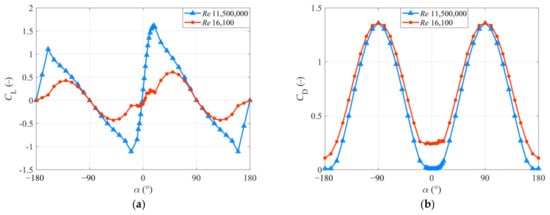
To accurately study the influence of RNE on the performance of airfoils, the DU40 airfoil is taken as the example to compare the lift and drag coefficients (
CL and
CD) of airfoils at the reference and model Reynolds numbers. The results are shown in
Figure 1, and α is the angle of attack. It shows that there are several significant changes in airfoil performance resulting from RNE. The
CL significantly decreases, and the
CD slightly increases. It means the peak
CL/
CD also decreases significantly. As the Blade Element Momentum (BEM) points that, the
CT of blade sections is mainly influenced by the peak
CL of airfoil, the valley
CD and the peak
CL/
CD of airfoil
[15][16][32,33]. Thus, to design a thrust match blade, airfoils with larger peak
CL, smaller valley
CD and larger
CL/
CD are needed first.
Figure 1. The aerodynamic performance of DU40 airfoil at the reference and model Reynolds numbers. (a) The lift coefficient. (b) The drag coefficient.
3. Airfoil Selection
3.1. Xfoil-AirfoilPrep-Matlab (XAM) System
3.1. XAM System
To find the required airfoils, the
CL and
CD of several airfoils should be calculated and compared with each other. Based on this goal, a XAM system, which integrates Xfoil
[17][34], AirfoilPrep
[18][35] and Matlab software, is proposed
in this study. This system can fulfill the calculation of the
CL and
CD of several airfoils at the full 360-degree angle of attack, the extraction of the critical data and the comparison of the aerodynamic performance of airfoils.
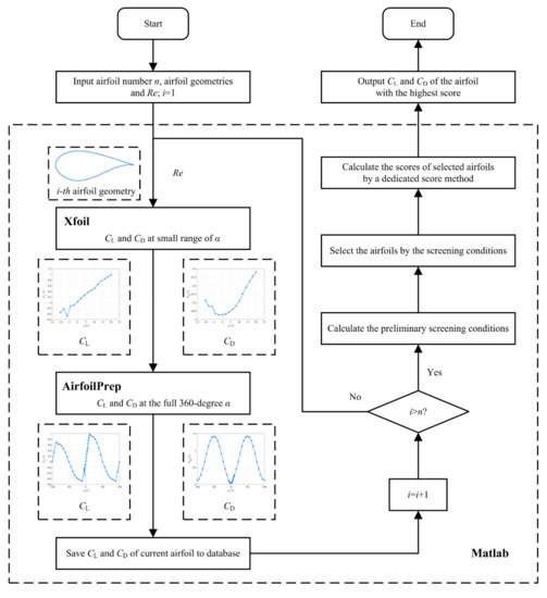
The flowchart of the XAM system is shown in
Figure 2. Firstly, the studied airfoil number, airfoil geometries and
Re are read. Secondly, a bat file is written based on airfoil geometries and used to drive the Xfoil. Thirdly, the
CL and
CD at a small range of
α are processed to the full 360-degree
CL and
CD data by AirfoilPrep. Fourthly, the preliminary screening conditions are determined according to the maximum peak
CL, the minimum valley
CD and the maximum peak
CL/
CD of airfoils. Then, several airfoils are selected based on the preliminary screening conditions. Afterward, the scores of the selected airfoils are calculated by a dedicated score method. Finally, the
CL and
CD of the airfoil with the highest score are output.
Figure 2.
The flow-chart of XAM system.
3.2. Result and Discussion of Airfoil Performance
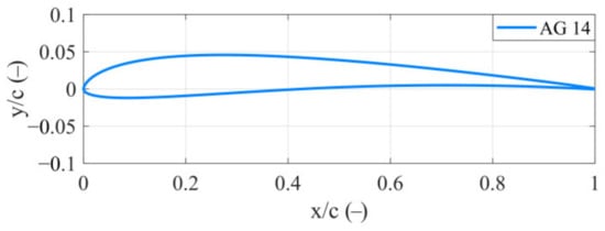
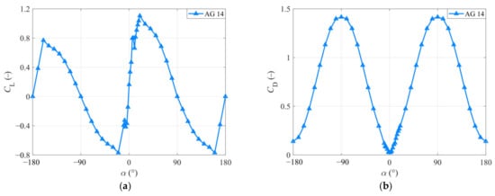
The geometry and aerodynamic performance of AG 14 airfoil at the model Reynolds number are shown in
Figure 3 and
Figure 4, respectively.
Figure 3.
The geometry of AG 14 airfoil.
Figure 4. The aerodynamic performance of AG 14 airfoil at the model Reynolds number. (
a) The lift coefficient. (
b) The drag coefficient.
4. Redesigning Blade Solution
4.1. Wide Tip Speed Ratio Search Method (WTSM)
4.1. WTSM
The rated thrust coefficient is usually taken as the optimization object of redesigning the blade in the previous studies. However, it cannot promise the thrust performance of the OFWT model matching the RWT blade under other working conditions. This will lead to deviations in research related to unsteady inflow wind, wake and control strategy. To solve this problem, a WTSM is proposed to design a wide TSR thrust-match blade
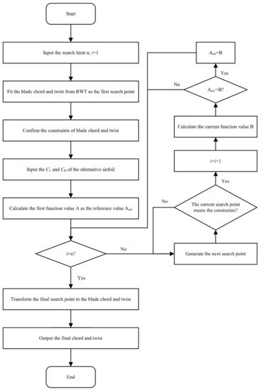
in this study. The WTSM reaches this goal by taking the thrust coefficients at multi-TSR as the optimization object in the design process. The flowchart of WTSM is shown in
Figure 5. First is fitting the blade chord and twist of the RWT blade to a quaternary polynomial and a quadratic polynomial, respectively. Second is clarifying the constraints of blade chord and twist. Then, selecting an appropriate alternative airfoil through the XAM system (AG 14 airfoil
in this study). Afterward, the blade chord and twist polynomial coefficients are taken as the design variables to search for the result with a minimum target value. Finally, the blade chord and twist are output.
Figure 5.
The flow-chart of WTSM.
4.2. Results
In this entry, the population of
grasshopper optimization algorithm (GOA
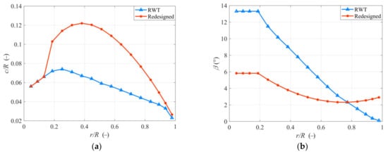
) is set as 4000, and the iteration is set as 10. The blade chord and twist results are compared with the RWT blade in
Figure 6. It shows that the redesigned blade has an increase in chord and a decrease in twist. The increased blade chord can catch more wind power and slightly increase the Reynolds number. The decreased twist will lead the airfoil, which has poor performance due to the RNE, to operate at a better angle of attack. Similar findings can be found in other studies
[19][20][21,24]. In addition, the smoothness of the chord and twist curve also prove the advantage of using the polynomial coefficients as the design variable.
Figure 6.
Comparison of the redesigned blade and the RWT blade. (a
) Chord. (b
) Twist.
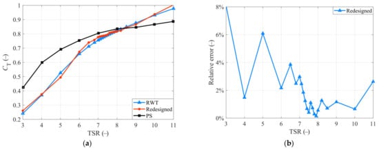
The comparison of the thrust coefficient between the redesigned blade and the RWT blade is shown in
Figure 7a. The relative error is shown in
Figure 7b. To show the effectiveness of WTSM, a blade redesigned by Pattern Search (PS) in 1/50th with Du et al.’s study is also present in
Figure 7a and denoted as PS
[21][25].
Figure 7. (
a) The thrust coefficient comparison of redesigned blade, RWT blade and PS blade. (
b) The relative error of redesigned blade to RWT blade.
4.3. Aerodynamic Analysis with Different Pitch Angle
To further study the capacity of the redesigned blade in researches related to control strategy, some
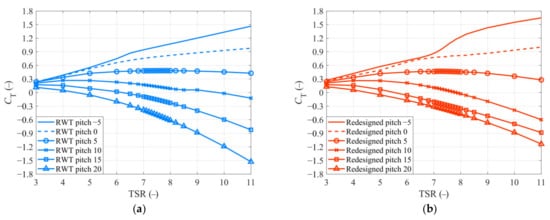
CT-TSR curves of the redesigned blade and RWT blade with different pitch angles are obtained from OpenFAST and presented in
Figure 8. It shows that the
CT of the RWT blade decrease with the increase of pitch angle, and this decrease is more obvious with the increase of TSR. Similar trends can also be found on the
CT-TSR curves of the redesigned blade. In this scenario, though some deviations can be found between the redesigned blade and the RWT blade except the 0 pitch angle, it still has a great potential in serving for research related to control strategy.
Figure 8.
The CT
-TSR curves with different pitch angles. (a
) RWT blade. (b
) Redesigned blade.
5. Conclusions
This entry proposes a XAM system to select the best airfoil for redesigning the blade first. Then a WTSM based on GOA is put forward to optimize the blade chord and twist of the redesigned blade. The main findings are summarized as follows:
- A XAM system is constructed to guide the airfoil selection. Based on the XAM system, 767 airfoils are compared with each other according to the preliminary screening conditions and the dedicated score method. Finally, the AG 14 airfoil is selected out as the best airfoil.
- A WTSM is proposed for a wide TSR thrust-match blade. Based on the WTSM, the blade chord and twist of the redesigned blade with AG 14 airfoil is optimized for a better thrust performance. The
- CT-TSR curve of the redesigned blade is compared with the RWT blade. Moreover, most of the relative errors are less than 5%, except for the working conditions that TSR = 3 (8%) and TSR = 5 (6%). It proves the thrust performance of the redesigned blade matches that of the RWT blade well at a 0 pitch angle.
- The thrust coefficients of the proposed redesigned blade in other pitch angles are calculated and compared to those of the RWT blade. Results show that the variations are consistent with the RWT blade. It means that the redesigned blade has great potential in the studies related to control strategy.