Your browser does not fully support modern features. Please upgrade for a smoother experience.
Submitted Successfully!
 +1 credit
Thank you for your contribution! You can also upload a video entry or images related to this topic.
For video creation, please contact our Academic Video Service.
| Version | Summary | Created by | Modification | Content Size | Created at | Operation |
|---|---|---|---|---|---|---|
| 1 | Yichuan Wang | + 1861 word(s) | 1861 | 2022-01-27 07:18:09 | | | |
| 2 | Dean Liu | Meta information modification | 1861 | 2022-01-29 03:33:50 | | |
Video Upload Options
We provide professional Academic Video Service to translate complex research into visually appealing presentations. Would you like to try it?
Cite
If you have any further questions, please contact Encyclopedia Editorial Office.
Wang, Y. Wheel Loader and Cushion Valve Design. Encyclopedia. Available online: https://encyclopedia.pub/entry/18991 (accessed on 24 June 2026).
Wang Y. Wheel Loader and Cushion Valve Design. Encyclopedia. Available at: https://encyclopedia.pub/entry/18991. Accessed June 24, 2026.
Wang, Yichuan. "Wheel Loader and Cushion Valve Design" Encyclopedia, https://encyclopedia.pub/entry/18991 (accessed June 24, 2026).
Wang, Y. (2022, January 29). Wheel Loader and Cushion Valve Design. In Encyclopedia. https://encyclopedia.pub/entry/18991
Wang, Yichuan. "Wheel Loader and Cushion Valve Design." Encyclopedia. Web. 29 January, 2022.
Copy Citation
A wheel loader is a kind of earth and stone construction machine widely used in highways, buildings, mines, and other construction projects.
wheel loader
hydrostatic steering system
AMESim
cushion valve
1. The Structure and Principle of the Cushion Valve
The hydraulic steering system of the loader is complex and the structure is difficult to modify. In order to solve the problem of steering vibration, an electro-hydraulic proportional valve is added between the A and B ports of the hydrostatic steering unit. This method uses hydraulic means connecting A and B ports to quickly consume energy during the stop process. In the actual work process, pressure fluctuations are difficult to determine, electro-hydraulic proportional valves are difficult to control, and the steering system does not have a corresponding pressure acquisition and processing system. Therefore, a cushion valve was designed to solve the problem of steering stop vibration.
The control strategy of the cushion valve: (1) When the steering action is completed, the high-pressure chamber oil is led to the low-pressure side through the cushion. The cushion absorbs the pressure shocks and effectively suppresses the repeated swing of the front frame and the cab of the loader; (2) When the low-pressure cavity of hydrostatic steering unit is negative pressure caused by vibration, the oil is supplemented from the tank through the one-way valve; (3) At the beginning of the steering, when the starting shock is too large, the starting shock will be reduced by the secondary relief valve. The structure principle of the cushion valve is shown in Figure 1. The A(B) port of the cushion valve is connected with the A(B) port of the rotary valve, and the T port is connected with the oil tank. The key component parameters of the cushion valve are shown in Table 1.
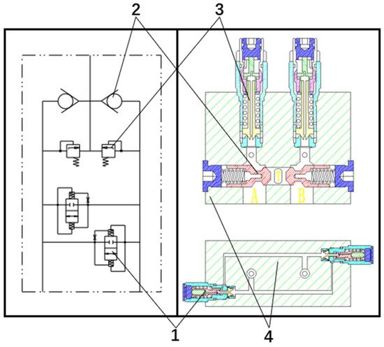
Figure 1. The structure and principle of cushion valve: 1—anti-vibration valve; 2—one-way valve; 3—secondary relief valve; 4—valve body.
Table 1. Cushion valve key component parameters.
| Parameter | Value | Parameter | Value |
|---|---|---|---|
| Plunger area | 150 mm2 | Valve seat area | 21 mm2 |
| Valve seat spring stiffness | 1.6 N/mm | Plunger spring stiffness | 14.3 N/mm |
| Plunger spring preload | 127.5 N | Valve seat spring preload | 8.7 N/mm |
| Damping hole diameter | 0.3 mm |
The structure and working principle of the anti-vibration valve are complex, and its structure is shown in Figure 2. The working principle is as follows: Port A and port B of the anti-vibration valve are respectively connected to the A and B ports of the steering gear. The high-pressure oil at port A and the low-pressure oil at port B were used as an example for analysis. The pressure oil enters the action chamber of the piston 8 through the hole in the valve seat 2, the ball valve 5 and the hole in the plunger 6. Overcoming the force of springs 1 and 7, the valve seat and plunger move to the left together. When the pressure reaches PS, the steering action is completed and the pressure drops. If there is no anti-vibration valve, recoil and oscillation will occur due to the energy storage effect of the hydraulic system. When P < PS, the plunger moves to the right under the force of the spring 7, and the valve seat is delayed due to the damping effect of the orifice 3. At this time, A is connected to B, and the high-pressure oil in A flows to B, causing the oil pressure in A to drop quickly.
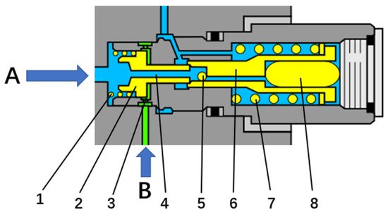
Figure 2. Working principle diagram of anti-vibration valve: 1—seat spring; 2—valve seat; 3—damped holes; 4—hole in the seat; 5—ball valve; 6—plunger; 7—plunger spring; 8—piston.
2. Simulation and Prototype Test
In order to better verify the optimization effect of the buffer valve on the steering performance of the wheel loader, the following simulation and prototype tests were carried out. The simulation and prototype test are comparison tests between the initial system and the system equipped with the cushion valve for steering emergency stop and swing steering wheel.
2.1. Function Verification Simulation Experiment of Cushion Valve
The simulation is a comparative test between the initial system and the system equipped with the cushion valve to simulate the emergency stop of the steering and swing steering wheel test. The steering emergency stop test refers to turning the steering wheel 120 degrees at the fastest speed, then releasing it. The swing steering wheel test refers to a test in which the torque applied to the steering wheel is: 0.5 s clockwise −0.5 s counterclockwise −0.5 s clockwise −0.5 s counterclockwise. The result is the steering angle of the loader and the pressure at the A and B ports of hydrostatic steering unit. The steering angle refers to the angle between the axis of the front frame and the rear frame of the loader.
The emergency stop of the steering simulation result is shown in Figure 3. The cushion valve greatly reduces the vibration of the loader’s steering stop. The performance is: The range of pressure fluctuation is reduced from 50 bar to 30 bar, and the number of pressure fluctuations is reduced from 6 times to once. When the steering is completed, the front frame is reduced from vibration 6 times to 0, and the vibration time is reduced from 1.5 s to 0.
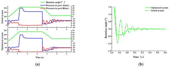
Figure 3. The emergency stop of the steering simulation result: (a) cylinder pressure and frame angle curve; (b) partial enlarged view of the steering angle.
The swing steering wheel simulation result is shown in Figure 4. After analyzing the simulation results, the cushion valve greatly reduces the pressure start shock and steering stop vibration of the loader. The main performance is: the starting impact pressure is reduced from 190 bar to 80 bar, the pressure fluctuation range is reduced from 130 bar to 30 bar, the number of pressure fluctuations is reduced from 9 to 2, the number of vibrations of the front frame is reduced from 9 to 1, and the vibration time is reduced from 2.1 s is reduced to 0.4 s. The original system still had pressure fluctuations and cab vibration during 5–6 s, but the optimized system no longer had pressure fluctuations and cab vibrations for 5–6 s.
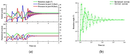
Figure 4. The swing steering wheel simulation result: (a) cylinder pressure and frame angle curve; (b) partial enlarged view of the steering angle.
In summary, the comparative simulation test verifies that the cushion valve has a significant improvement effect on pressure start shock and pressure fluctuation. The cushion valve can be used to optimize the hydraulic steering system of the wheel loader.
The swing steering wheel simulation result is shown in Figure 4. After analyzing the simulation results, the cushion valve greatly reduces the pressure start shock and steering stop vibration of the loader. The main performance is: the starting impact pressure is reduced from 190 bar to 80 bar, the pressure fluctuation range is reduced from 130 bar to 30 bar, the number of pressure fluctuations is reduced from 9 to 2, the number of vibrations of the front frame is reduced from 9 to 1, and the vibration time is reduced from 2.1 s is reduced to 0.4 s.
In summary, the comparative simulation test verifies that the cushion valve has a significant improvement effect on pressure start shock and pressure fluctuation. The cushion valve can be used to optimize the hydraulic steering system of the wheel loader.
2.2. Prototype Comparison Test
In order to accurately analyze the impact of the cushion valve on the steering system of the loader and study the optimization function of the steering stop vibration, it was necessary to install the cushion valve on the steering system of the loader to conduct a prototype test. The test prototype is still the 5-ton loader used in the previous test, and the test site is a flat asphalt road. For the severity of vibration, on the one hand, the driver’s feeling is subjectively judged; on the other hand, it is objectively judged by data. Since the driver’s subjective feelings cannot be quantified, this article uses pressure and acceleration to evaluate the steering effect. Therefore, pressure sensors are installed on the A and B ports of the hydraulic steering unit, and an accelerometer is arranged in the cab to measure and record the lateral acceleration of the loader. The sample vehicle test site and sensor installation location are shown in Figure 5. The test records, processes and analyzes the data by synchronously collecting the A and B port pressures of the hydraulic steering unit and the lateral acceleration signals of the cab. Through the observation results, the effect of the buffer valve on the optimization of the steering system of the loader is demonstrated. That is, the greater the pressure fluctuation of the steering cylinder, the greater the vibration amplitude of the loader frame, and the greater the lateral acceleration fluctuation of the cab, the more intense the vibration of the cab. Conversely, small pressure fluctuations and small accelerations prove that the vibration impact is small and the optimization effect is obvious.
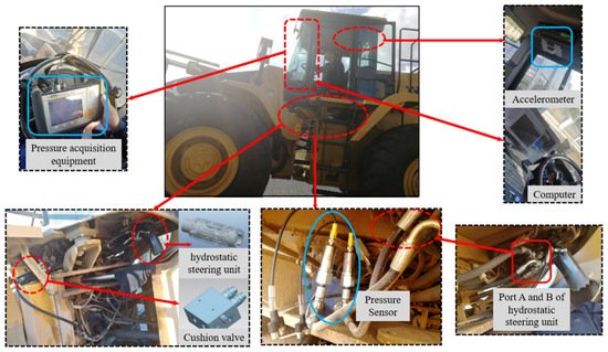
Figure 5. Layout of the test device.
The test results are shown in Figure 6. Compared with the test results of the original steering system loader, the pressure start shock at the beginning of the steering is reduced from 180 bar to 80 bar, and the pressure fluctuation after the sudden stop of the steering is reduced from twice to 0. The vibration amplitude of the cab is significantly reduced, and the acceleration range is reduced from 10 m/s2 to 2 m/s2. That is, the front frame of the loader stops shaking after swinging in the reverse direction after the steering stop action ends. It is verified by experiments that this hydraulic method has solved the problem of the loader’s steering vibration and suction. Also, it greatly reduced the start-up shock without affecting other operations.
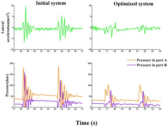
Figure 6. Test results steering emergency stop.
In order to test the cushion valve’s ability to absorb pressure shocks, a swing steering wheel comparison test was carried out. The swing steering wheel test refers to a test in which the torque applied to the steering wheel is: 0.5 s clockwise-0.5 s counterclockwise-0.5 s clockwise-0.5 s counterclockwise, so that the hydraulic steering unit performs multiple open-close-open tests. This test is different from the emergency stop test in that it will quickly open and close the steering gear many times. It can make the energy of multiple pressure pulses unable to be released, causing the system to vibrate violently, which can better reflect the function of the cushion valve to absorb pressure shocks and its dynamic characteristics.
The test results of the swing steering wheel are shown in Figure 7. Swing the steering wheel four times, the oil pressure in the steering gear rises up to 100 bar, and the lateral acceleration of the cab is up to 5 m/s2. After the operation is completed, the front frame of the loader stops swinging after a reverse reversal, and the pressure at the A and B ports of the steering gear fluctuates once, and the fluctuation duration is 0.3 s. That is, the front frame of the loader stops shaking after swinging in the reverse direction after the steering stop action ends. Compared with the test results of the original steering system loader, the buffer valve reduces the pressure start shock at the beginning of the steering from 250 bar to 100 bar, the pressure fluctuation after the steering emergency stop is reduced from 4 times to 1 time, and the vibration amplitude of the cab is significantly reduced. The main performance is: the acceleration change range is reduced from 14 m/s2 to 5 m/s2.
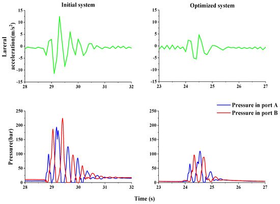
Figure 7. Test results of swing steering wheel.
Information
Subjects:
Agricultural Engineering
Contributor
MDPI registered users' name will be linked to their SciProfiles pages. To register with us, please refer to https://encyclopedia.pub/register
:
View Times:
1.4K
Revisions:
2 times
(View History)
Update Date:
29 Jan 2022
Table of Contents


Notice
You are not a member of the advisory board for this topic. If you want to update advisory board member profile, please contact office@encyclopedia.pub.
OK
Confirm
Only members of the Encyclopedia advisory board for this topic are allowed to note entries. Would you like to become an advisory board member of the Encyclopedia?
Yes
No
${ textCharacter }/${ maxCharacter }
Submit
Cancel
Back
Comments
${ item }
|
${ item.createdUser.fullName }
${ item.createdAt }
${ item.vote }
${ item.reply }
Delete
${ reply.createdUser.fullName }
${ reply.createdAt }
${ reply.vote }
Delete
There is no reply to this comment~
${ item.replyTextCharacter }/${ item.replyMaxCharacter }
Submit
Cancel
More
No more~
There is no comment~
${ textCharacter }/${ maxCharacter }
Submit
Cancel
${ selectedItem.replyTextCharacter }/${ selectedItem.replyMaxCharacter }
Submit
Cancel
Confirm
Are you sure to Delete?
Yes
No